In modern automotive structural design, securing maximum occupant safety while achieving aggressive vehicle lightweighting goals is a critical engineering challenge. The car b pillar serves as the vital central vertical backbone of the Body-in-White (BIW) structure, bearing the brunt of energy distribution during side collisions and rollover events. As global OEMs and Tier-1 procurement leaders seek to build resilient, cost-optimized supply chains, Vietnam has emerged as a high-precision manufacturing hub. Automech delivers end-to-end OEM manufacturing solutions for automotive b pillars—combining advanced progressive stamping, high-strength steel processing, robotic welding, and IATF 16949 quality standards.

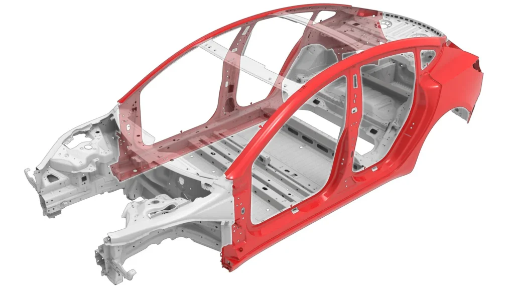
High-strength steel B-pillar structural reinforcement highlighted in red on vehicle body-in-white (BIW)
1. Car B Pillar: Structure, Manufacturing Process & Trusted Automotive B Pillar Manufacturer in Vietnam
1.1 What Is a Car B Pillar?
1.1.1 Definition of a Car B Pillar
A car b pillar (also known as the center pillar) is a structural vertical assembly positioned between the front and rear side door openings of a multi-door vehicle. It functions as a primary load-bearing column that physically locks the upper roof structure to the floor frame.
1.1.2 Location of the B Pillar in a Vehicle Body
The b pillar is situated directly in the middle section of the passenger cabin. It forms the structural framing for the trailing edge of the front side door and the leading edge of the rear passenger door.
1.1.3 Difference Between A, B and C Pillars
- A-Pillar: Positioned at the front of the cabin on either side of the windshield, holding the forward roof edge and front door hinges.
- B-Pillar: Located centrally between door panels, engineered specifically to resist cabin intrusion during lateral impacts and roof crush forces.
- C-Pillar: Located behind the rear side doors, supporting the rear roof section and rear window glass assembly.
1.1.4 Relationship Between the B Pillar and the Body-in-White (BIW)
As a core structural component of the Body-in-White (BIW), the car b pillar links three primary BIW sub-assemblies: the longitudinal roof rail, the outer rocker panel, and the floor pan frame. It acts as the central cross-bracing pillar for overall torsional stability.
1.2 Functions of the Automotive B Pillar
1.2.1 Supporting the Vehicle Roof Structure
The car b pillar serves as a critical vertical compression column, sustaining static roof mass and dynamic overhead loading during vehicle operation.
1.2.2 Enhancing Side-Impact Crash Protection
During lateral impact scenarios (such as side-swipe or T-bone broadside collisions), the b pillar acts as a high-strength shield that limits side door penetration into the passenger compartment.
1.2.3 Improving Roof Crush Resistance
In rollover accidents, the b pillar maintains vertical structural resistance to satisfy stringent roof strength tests (such as FMVSS 216 standards), preventing roof collapse over occupant heads.
1.2.4 Maintaining Passenger Compartment Integrity
By maintaining its structural geometry under severe kinetic loads, the b pillar ensures that door frames remain functional for rapid emergency passenger evacuation.
1.2.5 Supporting Door Hinges, Latches and Seat Belt Anchorage
The b pillar serves as a multi-functional mechanical substrate, hosting the front door latch striker, rear door hinges, and upper safety belt turning loops.
1.2.6 Improving Vehicle Rigidity and Structural Performance
Higher structural stiffness in the b pillar directly increases overall chassis torsional and bending rigidity, enhancing vehicle handling response and steering stability.
1.2.7 Contributing to NVH (Noise, Vibration & Harshness) Performance
A rigidly attached b pillar mitigates body flex during cornering over rough terrain, reducing cabin rattles, squeaks, and airborne acoustic resonance.

Close-up structural diagram of automotive B-pillar reinforcement showing key load-bearing sections
2. Car B Pillar Design and Engineering
2.1 Anatomy of a B Pillar
2.1.1 Outer Panel
The exterior aesthetic cover stamped to align perfectly with exterior body lines, providing mounting surfaces for door seals and trim.
2.1.2 Inner Reinforcement
The primary structural load-bearing member, typically pressed from ultra-high-strength steel alloys to deliver high yield strength.
2.1.3 Reinforcement Plates
Targeted supplementary steel patches welded at stress concentration points to bolster localized structural strength without adding dead weight.
2.1.4 Mounting Interfaces
Precision-engineered stamped holes and nut-welded mounting points designed to secure latches, door hinges, and interior trim clips.
2.1.5 Seat Belt Reinforcement Area
A heavy-gauge localized reinforcement plate designed to sustain extreme tensile loads transferred by the seatbelt pretensioner during dynamic braking or impact.
2.2 Structural Design Requirements
2.2.1 Crash Energy Management
Engineered using tailored material zones to combine high strength at the upper cabin level with controlled deformation characteristics at the base.
2.2.2 Load Path Optimization
Optimized geometric profiles direct side-impact kinetic energy away from the ribcage area into the roof rail and floor sill structures.
2.2.3 Structural Reinforcement Design
Incorporating multi-thickness tailored blanks or internal box-section channels to maximize structural section modulus.
2.2.4 Weight Reduction Strategies
Utilizing advanced high-strength steel grades and optimized stamping geometry to reduce part mass, assisting OEM vehicle lightweighting and range targets.
2.2.5 Manufacturability (DFM)
Ensuring part draw depths, flange radii, and hole spacing accommodate high-speed stamping, minimal die wear, and robotic welding access.

Side outer frame and B-pillar assembly highlighted in red on car body structure
2.3 Materials Used for Automotive B Pillars
2.3.1 Mild Steel
Selected primarily for non-structural outer covers where deep drawability and smooth surface finishing are prioritized over strength.
2.3.2 High-Strength Steel (HSS)
Provides yield strengths up to 300–500 MPa, making it ideal for moderate load-bearing internal reinforcement plates and brackets.
2.3.3 Advanced High-Strength Steel (AHSS)
Includes Dual Phase (DP) and Complex Phase (CP) steels (600–1000 MPa) that offer superior work hardening and impact energy absorption.
2.3.4 Ultra High-Strength Steel (UHSS)
Delivers extreme tensile strength (>1000 MPa) for structural inner reinforcements, requiring high-tonnage stamping equipment.
2.3.5 Press Hardened Steel (PHS)
Boron steel alloys (e.g., 22MnB5) hot-stamped to achieve tensile strengths exceeding 1500 MPa, delivering maximum resistance to cabin intrusion.
3. Car B Pillar Manufacturing Process
3.1 Manufacturing Workflow
3.1.1 Engineering Design & CAD Review
3D surface design validation, material callout check, and finite element analysis (FEA) simulation against OEM structural targets.
3.1.2 Material Selection
Verification of certified steel coil chemistry, thickness tolerances, and corrosion protection coatings (GI/GA).
3.1.3 Tool & Die Development
Designing and precision machining progressive or transfer stamping dies equipped with springback compensation.
3.1.4 Prototype Manufacturing
Producing short-run soft-tool or laser-cut prototype samples to perform physical fitment, CMM, and crash testing validation.
3.1.5 Mass Production
Continuous automated stamping, robotic spot welding assembly, inline quality monitoring, and protective packaging.

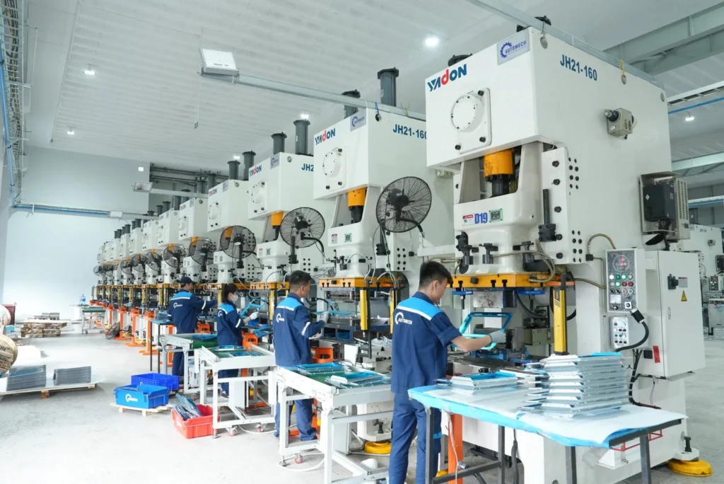
High-capacity mechanical press stamping line with operators at Automech factory
3.2 Metal Stamping Process
3.2.1 Coil Feeding
Automated uncoiling, flattening, and feeding of heavy-gauge steel strips into the press line.
3.2.2 Blanking
Precision shearing of steel coils into tailored flat blanks ready for press operations.
3.2.3 Piercing
Punching required structural mounting holes, clearance cutouts, and positioning datum points.
3.2.4 Forming
High-tonnage hydraulic or mechanical drawing of flat blanks into complex 3D b pillar geometries.
3.2.5 Bending
Flanging edge profiles to create tight mating surfaces for adjacent BIW panel fitment.
3.2.6 Trimming
Precision cutting and laser trimming of excess flash material along part perimeters.
3.2.7 Calibration
Final sizing pass to lock in tight dimensional tolerances and correct minor metal springback.

Technician operating a precision body welding jig fixture at the assembly line
3.3 Hot Stamping vs Cold Stamping
3.3.1 Hot Stamping Process
Blanks are heated to ~900°C in a furnace, formed in a chilled die, and quenched rapidly to create a fully martensitic ultra-high-strength structure.
3.3.2 Cold Stamping Process
Sheet metal is formed at ambient room temperature on high-tonnage mechanical or servo press lines, ideal for ductile steel grades.
3.3.3 Advantages and Limitations
- Hot Stamping: Offers zero springback and ultimate tensile strength (>1500 MPa); Limitations: Higher capital investment and longer cycle times.
- Cold Stamping: Higher SPM production speed and lower tooling costs; Limitations: Subject to springback challenges on ultra-high-strength alloys.
3.3.4 Selection Criteria for OEM Programs
Chosen based on OEM safety crash rating targets, part complexity, annual volume requirements, and program cost limits.

Automated stamping workshop featuring a row of robotic transfer arms and press machines
3.4 Welding Assembly Process
3.4.1 Spot Welding
Resistance Spot Welding (RSW) fuses the inner reinforcement, outer cover, and internal mounting plates into a unified sub-assembly.
3.4.2 Laser Welding
Precision laser seam welding delivers continuous structural joints, increasing assembly torsional stiffness while reducing flange widths.
3.4.3 Robotic Welding Systems
Automated 6-axis welding robots execute consistent weld schedules with real-time current and pressure feedback monitoring.
3.4.4 Fixture-Controlled Assembly
High-precision pneumatic welding fixtures hold all stamped components in exact geometric orientation during joinery.
3.4.5 Dimensional Validation
In-line laser tracking and CMM check key assembly points against 3D CAD nominals before shipping.

Automated robotic welding cell integrated with industrial fume extraction system
4. BIW Integration and Structural Performance
4.1 B Pillar Integration within Body-in-White
4.1.1 Connection to Roof Rail
Top flanges are spot-welded directly to the main roof longitudinal rail to form the upper side-structure load node.
4.1.2 Floor Structure Integration
Bottom attachment plates anchor into the floor cross-members, transferring lateral impact loads across the floor frame.
4.1.3 Rocker Panel Connection
Lower section structural members join firmly with the side rocker panel (sill), creating a rigid lower torque box.
4.1.4 Door Frame Assembly
Precision flanges create a continuous perimeter track for door weatherstrip seals and acoustic insulation.
4.2 Crash Safety Performance
4.2.1 Side-Impact Protection
Prevents deep intrusion into occupant survival space during FMVSS 214 and Euro NCAP lateral barrier tests.
4.2.2 Roof Crush Performance
Meets strict rollover safety requirements by sustaining static crush loads up to 4x to 5x the vehicle’s unladen weight.
4.2.3 Occupant Safety
Works in tandem with curtain airbags and seatbelt pretensioners to maintain a protective safety cage.
4.2.4 Regulatory Compliance
Full engineering compliance with international automotive standards including FMVSS, ECE regulations, and C-NCAP.

Engineers setting up and calibrating precision body welding jigs at Automech factory
4.3 NVH Optimization
4.3.1 Structural Stiffness
High localized bending stiffness elevates body natural frequency modes out of excitation ranges caused by road roughness.
4.3.2 Vibration Reduction
Prevents mid-body structural flex, eliminating door latch creaks, seal squeaks, and panel drumming.
4.3.3 Acoustic Performance
Enables exact door frame seal compression, eliminating high-speed wind noise and external road rumble.
5. Manufacturing Quality Requirements
5.1 Dimensional Accuracy
5.1.1 Critical Tolerances
Strict manufacturing tolerances (typically within ±0.5 mm for mounting holes and profile surfaces).
5.1.2 GD&T Requirements
Rigid Geometric Dimensioning & Tolerancing controls covering hole positions, profile tolerances, and datum alignment.
5.1.3 Springback Compensation
Advanced CAD surface morphing and physical die tuning offset elastic material springback in high-strength steels.
5.2 Surface Quality
5.2.1 Burr Control
Strict die clearance control limits edge burrs, preventing micro-cracking during forming and protecting robotic handling suction cups.
5.2.2 Surface Finish
Class-A visual surface quality standards on outer panels, completely free from scratches, press marks, or oil dimples.

Formed metal bracket component with projection welded nuts for automotive body assembly
5.2.3 Corrosion Protection
Use of pre-galvanized (GI/GA) or aluminum-silicon (AlSi) coated steel sheets to ensure long-term rust resistance.
5.2.4 E-Coating Compatibility
Clean, residue-free part surfaces ensuring optimal electro-deposition coating adhesion during OEM paint shop dip cycles.
5.3 Inspection Systems
5.3.1 CMM Inspection
High-precision Coordinate Measuring Machines verify complex 3D profiles and hole locations against CAD models.
5.3.2 Gauge Inspection
Precision physical checking fixtures for fast, operator-driven dimensional verification on the shop floor.
5.3.3 Vision Inspection
In-line camera systems automatically verify weld nut presence, hole counts, and structural sealant bead continuity.
5.3.4 First Article Inspection (FAI)
Comprehensive dimensional and metallurgical teardown validation prior to signing off on production runs.
5.3.5 In-Process Quality Control
Real-time monitoring of press tonnage curves, weld current logs, and destructive chisel/tear-down testing.
6. Automotive Quality Standards
6.1 Quality Management Systems
6.1.1 ISO 9001
Foundational standard governing organizational quality management systems across manufacturing operations.
6.1.2 IATF 16949
The global automotive quality standard defining strict process controls, continuous improvement, and defect prevention.

Quality control team inspecting small stamped metal auto parts at assembly workstations
6.2 Automotive Core Tools
6.2.1 APQP
Advanced Product Quality Planning structures product development from initial design review through serial production launch.
6.2.2 PPAP
Production Part Approval Process provides OEMs with complete 18-element proof of process capability and sample quality.
6.2.3 FMEA
Failure Mode and Effects Analysis (DFMEA & PFMEA) systematically identifies and eliminates potential design and manufacturing risks.
6.2.4 Control Plan
Outlines required inspection points, test frequencies, and containment action plans for every step of production.
6.2.5 MSA
Measurement System Analysis (Gage R&R) ensures all measuring gauges and CMM equipment deliver accurate, repeatable data.
6.2.6 SPC
Statistical Process Control tracks critical product characteristics (Cp / Cpk ≥ 1.67) to guarantee process stability.
6.2.7 Full Traceability
Complete raw material heat number, stamping line, weld station, and inspection batch tracking via laser-etched QR codes.

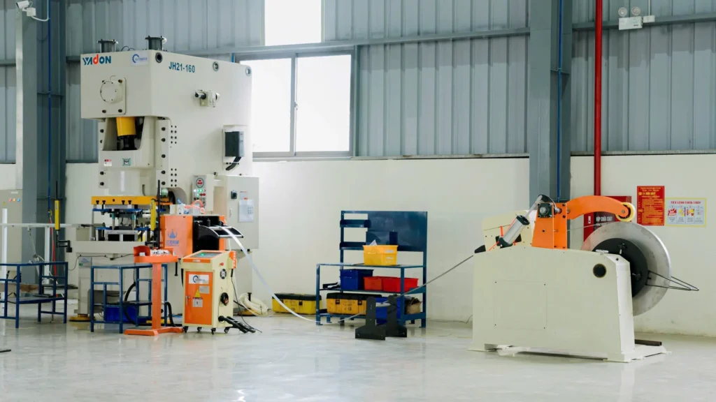
Heavy-duty Yadon 200T stamping press line equipped with automatic coil feeding system
7. OEM Supplier Selection Guide
7.1 How to Choose a Car B Pillar Supplier
7.1.1 Engineering Capability
Prioritize suppliers offering in-house DFM analysis, die simulation, and joint structural optimization.
7.1.2 BIW Manufacturing Experience
Look for a track record in producing high-strength structural Body-in-White components for automotive OEMs.
7.1.3 Stamping Capacity
Ensure access to high-tonnage press lines (630T to 2000T) capable of blanking and forming advanced high-strength steels.
7.1.4 Welding Automation
Automated robotic spot and laser welding cells capable of maintaining tight geometric tolerances across high volumes.
7.1.5 Tooling Development
In-house tool shop capabilities for quick die maintenance, engineering change order (ECO) implementation, and repair.
7.1.6 Quality Certifications
Mandatory active IATF 16949 certification verified by accredited third-party auditing bodies.
7.1.7 Export Experience
Demonstrated expertise in international packaging, customs documentation, and global supply chain logistics.
7.1.8 Cost Competitiveness
Transparent cost breakdown modeling that balances competitive material sourcing, conversion costs, and freight.

Robotic welding station processing structural automotive chassis parts at the plant
7.2 Automotive Supplier Qualification Checklist
7.2.1 Technical Capability Assessment
Review CAD software compatibility, FEA simulation tools, press tonnage specs, and robotic cell availability.
7.2.2 Production Capacity Review
Evaluate overall equipment effectiveness (OEE), shift flexibility, floor space, and material storage capacity.
7.2.3 Quality Audit
Inspect active IATF 16949 certifications, metrology lab CMM calibration records, and SPC tracking charts.
7.2.4 Logistics Capability
Verify JIT/JIS delivery readiness, export packaging standards, VCI corrosion protection, and sea freight handling.
7.2.5 Continuous Improvement Programs
Review historical metrics for scrap reduction, Kaizen implementations, and internal yield improvements.
8. Why Source Car B Pillars from Vietnam?
8.1 Vietnam’s Growing Automotive Manufacturing Ecosystem
8.1.1 Skilled Manufacturing Workforce
A highly skilled, agile engineering workforce with deep expertise in mechanical manufacturing, CNC machining, and automated welding.
8.1.2 Modern Production Facilities
Modern industrial parks housing state-of-the-art stamping press lines, robotic assembly cells, and metrology labs.
8.1.3 Competitive Manufacturing Costs
Favorable conversion costs and competitive labor rates offer substantial unit cost savings for complex structural stampings.
8.1.4 Strategic Supply Chain Location
Direct maritime access through major deep-water ports enables efficient shipping routes to North America, Europe, and Asia.

Panoramic aerial view of Automech Parts manufacturing factory facility
8.2 Vietnam vs Alternative China Sourcing
8.2.1 Cost Comparison
Vietnam provides attractive manufacturing cost structures, reducing component landed costs for global Tier-1 buyers.
8.2.2 Quality Standards
Vietnam’s tier automotive suppliers operate under strict IATF 16949 quality systems, matching global OEM expectations.
8.2.3 Supply Chain Diversification (China+1)
Sourcing from Vietnam provides critical supply chain resilience, hedging against single-region tariff and geopolitical risks.
8.2.4 Trade Advantages for US & Europe
Bilateral trade agreements and favorable tariff standings provide clear import duty advantages for Western buyers.
9. Trusted Car B Pillar Manufacturer in Vietnam – Automech
9.1 Automotive Manufacturing Capabilities
9.1.1 Automotive Metal Stamping
High-precision stamping lines processing mild steel, HSS, and UHSS structural parts up to thick gauges with tight tolerances.
9.1.2 BIW Manufacturing
Dedicated production lines for Body-in-White assemblies including b pillars, cross car beams, A-pillars, and chassis reinforcements.
9.1.3 Robotic Welding Assembly
Automated multi-axis robotic spot welding cells delivering continuous structural joints and repeatable geometry.
9.1.4 Structural Component Manufacturing
End-to-end production of safety-critical structural components designed to meet demanding OEM crash requirements.
9.1.5 Tooling & Fixture Design
In-house tooling team specializing in progressive dies, transfer dies, and automated welding assembly fixtures.
9.2 Engineering & Production Strengths
9.2.1 DFM Engineering Support
Early supplier involvement (ESI) providing technical feedback to optimize part geometry, material yield, and die life.
9.2.2 Prototype Development
Rapid soft-tooling prototyping capability for fast sample builds, early fitment checks, and physical testing.
9.2.3 Pilot Production
Controlled pilot runs to validate process capability (Cpk) and lock in standard operating procedures before SOP.
9.2.4 Mass Production
Scalable manufacturing infrastructure operating under lean principles, preventive maintenance, and real-time OEE tracking.
9.2.5 High-Strength Steel Processing
Specialized technical know-how in forming, piercing, and springback control for advanced high-strength steel grades.

High-speed Yadon stamping press line integrated with KUKA robotic transfer arms
9.3 Quality Assurance
9.3.1 CMM Measurement
Climate-controlled metrology laboratory equipped with 3D CMM machines for full GD&T inspection and surface scanning.
9.3.2 Traceability System
Laser-etched QR coding linking every finished component back to its raw material heat lot and press run details.
9.3.3 OEM Quality Documentation
Complete PPAP Level 3 documentation packages including FMEA, Control Plans, MSA studies, and mill test certificates.
9.3.4 Export Quality Management
Export-grade anti-corrosion packaging utilizing VCI barrier bags and custom steel dunnage to protect structural parts during ocean transit.
9.4 Global Export Experience
9.4.1 US Automotive Customers
Proven track record delivering high-quality structural stampings and welded sub-assemblies to North American buyers.
9.4.2 European Automotive Projects
Experienced in executing engineering programs compliant with European OEM standards, DIN guidelines, and REACH/RoHS rules.
9.4.3 OEM & Tier Supplier Collaboration
Seamless technical coordination and program management with Tier-1 system integrators and global OEM purchasing teams.

Skilled welder performing manual MIG/MAG welding on automotive tubular structural joints
10. RFQ Process for Car B Pillar Manufacturing
10.1 Information Required for RFQ
10.1.1 2D Drawings
Detailed engineering drawings specifying dimensions, GD&T callouts, surface finishes, material grades, and key inspection datums.
10.1.2 3D CAD Models
Native or neutral 3D CAD files (STEP, IGES, CATIA) required for accurate DFM analysis and tooling feasibility studies.
10.1.3 Material Specifications
Exact material standard designation (e.g., DP600, 22MnB5), nominal wall thickness, and required surface coating (GI/GA/AlSi).
10.1.4 Annual Volume
Target Estimated Annual Volume (EAV), project lifecycle duration, and expected delivery batch sizes.
10.1.5 Quality Requirements
Specific OEM test standards, inspection frequency requirements, and required PPAP submission level.

Stamped high-strength steel bracket component for automotive structural reinforcement
10.2 Engineering Review
10.2.1 DFM Analysis
Comprehensive evaluation of part geometry to identify deep draw risks, thinning concerns, and springback behavior.
10.2.2 Tooling Feasibility
Selecting die configurations (progressive vs. transfer), press tonnage allocation, and line automation layout.
10.2.3 Manufacturing Cost Evaluation
Transparent cost breakdowns covering raw material utilization, press machine rates, welding labor, and die amortization options.
10.2.4 Lead Time Planning
Detailed program schedules mapping out die design, tooling build, prototype sample delivery, PPAP sign-off, and mass production SOP.
10.3 Call to Action
10.3.1 Request an RFQ
Take the next step in optimizing your automotive structural component sourcing. Send your project specifications and volume requirements to Automech’s technical engineering team today for a comprehensive commercial proposal.
10.3.2 Upload Technical Drawings
Submit your 2D drawings and 3D CAD files directly to our engineering portal for immediate DFM analysis and manufacturing feasibility review.
10.3.3 Request Supplier Qualification Package
Contact our automotive division to receive Automech’s full supplier information package, including IATF 16949 certificates, machinery lists, and customer references.
10.3.4 Contact the Automotive Engineering Team
Engage directly with our English-speaking technical sales engineers in Vietnam to discuss your upcoming vehicle program timeline and custom tooling requirements.

Precision stamped metal mounting plate with ribbing for vehicle chassis assembly
11. Featured Snippet Opportunities
11.1 Definition Snippet
11.1.1 What Is a Car B Pillar?
A car b pillar is the central vertical steel structural column positioned between a vehicle’s front and rear side doors. It connects the roof rail to the rocker panel, serving as a primary load-bearing barrier that protects occupants during lateral crashes and vehicle rollovers.
11.2 List Snippet
11.2.1 Key Functions of a Car B Pillar
- Supports the vertical static weight and dynamic load of the vehicle roof.
- Absorbs and redirects kinetic impact forces during side-impact crashes.
- Prevents passenger cabin collapse during rollover accidents (roof crush resistance).
- Serves as a rigid anchor point for front seat belts, door latches, and rear door hinges.
- Enhances chassis torsional rigidity and overall NVH acoustic performance.
11.3 Process Snippet
11.3.1 Car B Pillar Manufacturing Process
- Coil Feeding & Blanking: Steel coils are uncoiled, flattened, and cut into flat metal blanks.
- Press Stamping: High-tonnage presses execute drawing, forming, trimming, and piercing operations.
- Hot Stamping (Optional): Boron steel is heated to ~900°C and quenched in the die for tensile strength >1500 MPa.
- Robotic Welding: Outer covers, inner reinforcements, and anchor plates are fused via automated spot welding.
- Quality Inspection: CMM laser scanning and physical checking fixtures verify strict GD&T tolerances.
11.4 Comparison Table
11.4.1 Hot Stamping vs Cold Stamping for B Pillars
| Feature / parameter | Hot stamping (press hardening) | Cold stamping |
| Material types | Boron Steel (e.g., 22MnB5) | Mild Steel, HSS, AHSS, DP Steel |
| Tensile strength | Ultra-High (≥1500 MPa) | Moderate to High (300 – 1000 MPa) |
| Springback control | Near zero springback | Requires active die compensation |
| Part complexity | Deep draws in single stroke | Multi-stage forming required |
| Tooling & energy cost | Higher capital expenditure | Standard stamping press cost |
| Primary use case | Safety-critical intrusion barriers | Outer covers & secondary supports |
11.5 Checklist Snippet
11.5.1 How to Choose a Reliable Car B Pillar Supplier
- Certifications: Must hold active IATF 16949 quality certification.
- Tonnage Capacity: High-tonnage press lines available (630T–2000T).
- Automated Joinery: Robotic spot welding and laser cells for repeatable geometry.
- Engineering Support: In-house DFM, FEA simulation, and die design tools.
- Metrology Lab: Climate-controlled CMM lab with complete APQP/PPAP documentation.

Formed sheet metal structural reinforcement component for automotive B-pillar assembly
12. People Also Ask (PAA)
12.1 What is a Car B Pillar?
A car b pillar is the middle vertical column on a car frame located between the front and rear doors that links the roof structure to the vehicle floor.
12.2 What does the B Pillar do in a vehicle?
It provides structural support to the roof, anchors front seat belt pretensioners and door latches, increases chassis stiffness, and shields occupants during side impacts.
12.3 Why is the B Pillar important for crash safety?
The b pillar acts as a central crash barrier during side collisions and rollovers, resisting intrusion into the passenger seating area to reduce occupant injury risks.
12.4 What materials are used to manufacture automotive B Pillars?
Automotive b pillars are manufactured using High-Strength Steel (HSS), Advanced High-Strength Steel (AHSS), Ultra High-Strength Steel (UHSS), and Press Hardened Boron Steel (PHS).
12.5 What is the difference between hot stamped and cold stamped B Pillars?
Hot stamped pillars are heated and quenched in-die to achieve tensile strengths above 1500 MPa with zero springback. Cold stamped pillars are formed at room temperature for ductile steel grades up to 1000 MPa.
12.6 How are automotive B Pillars manufactured?
They are produced by stamping steel sheets into inner and outer profiles using high-tonnage press lines, which are then assembled with reinforcement plates using robotic spot welding.
12.7 How do I choose a reliable Car B Pillar manufacturer?
Select an IATF 16949-certified supplier with strong DFM engineering support, high-tonnage stamping presses, automated robotic welding, and complete CMM metrology testing capabilities.

Body-in-White (BIW) structure with specific structural joint reinforcement location
13. Internal Linking Strategy
13.1 Core Cluster Pages
13.1.1 Automotive Structural Components
Explore our full line of engineered BIW safety structures and body stampings.
13.1.2 BIW Automotive Manufacturer Vietnam
Learn more about Automech’s comprehensive Body-in-White manufacturing capabilities in Vietnam.
13.1.3 Cross Car Beam
Discover our precision-engineered cross car beam assemblies for instrument panel support.
13.1.4 Car A Pillar
View our A-pillar metal stamping and assembly solutions for vehicle front structures.
13.1.5 Car C Pillar
Read about our rear roof structural supports and C-pillar component manufacturing.
13.1.6 Automotive Stamping
Discover our high-tonnage metal stamping capacities for automotive OEM programs.
13.1.7 Automotive Welding Assembly
Learn about our robotic spot welding cells and automated joinery infrastructure.
13.1.8 Automotive Structural Parts
Browse our portfolio of high-strength structural metal stampings for global vehicle programs.
13.2 Supporting Pages
13.2.1 Automotive Stamping Supplier Vietnam
Why leading global automotive buyers source precision metal stampings from Vietnam.
13.2.2 Automotive Welding Fixture
Learn about our custom in-house design and fabrication of precision welding fixtures.
13.2.3 Automotive Tooling Manufacturer
Explore our tool & die engineering capabilities for progressive and transfer dies.
13.2.4 BIW Welding Fixture
How our high-precision clamping fixtures ensure exact geometric tolerances for BIW assemblies.
13.2.5 Alternative China Automotive Supplier
Diversify your automotive supply chain with reliable, high-quality manufacturing from Vietnam.
Automech Mechanical Equipment and Solutions Joint Stock Company
Head Office: No. 285 Phuc Loi Street, Phuc Loi Ward, Hanoi City
Da Nang Branch: No. 20 Nguyen Sinh Sac Street, Hoa Khanh Ward, Da Nang City
Ho Chi Minh Branch: No. 84, Street No. 10, Van Phuc Urban Area, Hiep Binh Ward, Ho Chi Minh City
Factory No. 1: Automech Automation Equipment, Mold & Tool Manufacturing Factory – Automech Demo Center: Dinh Tram Industrial Park, Nenh Ward, Bac Ninh City, Vietnam
Factory No. 2: Automech Parts Manufacturing & Component Fabrication Factory: Viet Nhat Industrial Cluster, Xuan Cam Commune, Bac Ninh City, Vietnam
Hotline: 0902 997 331
Website: https://automechmfg.com/
Fanpage: https://www.facebook.com/automech.mfg/
YouTube: https://www.youtube.com/@Automechmfg