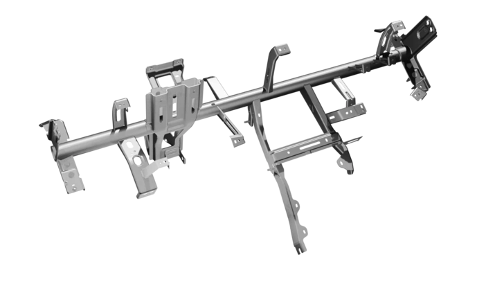
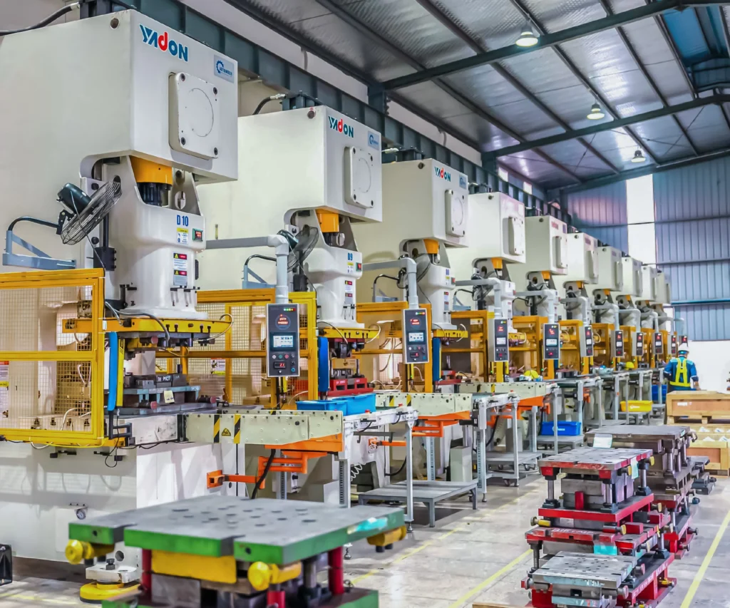
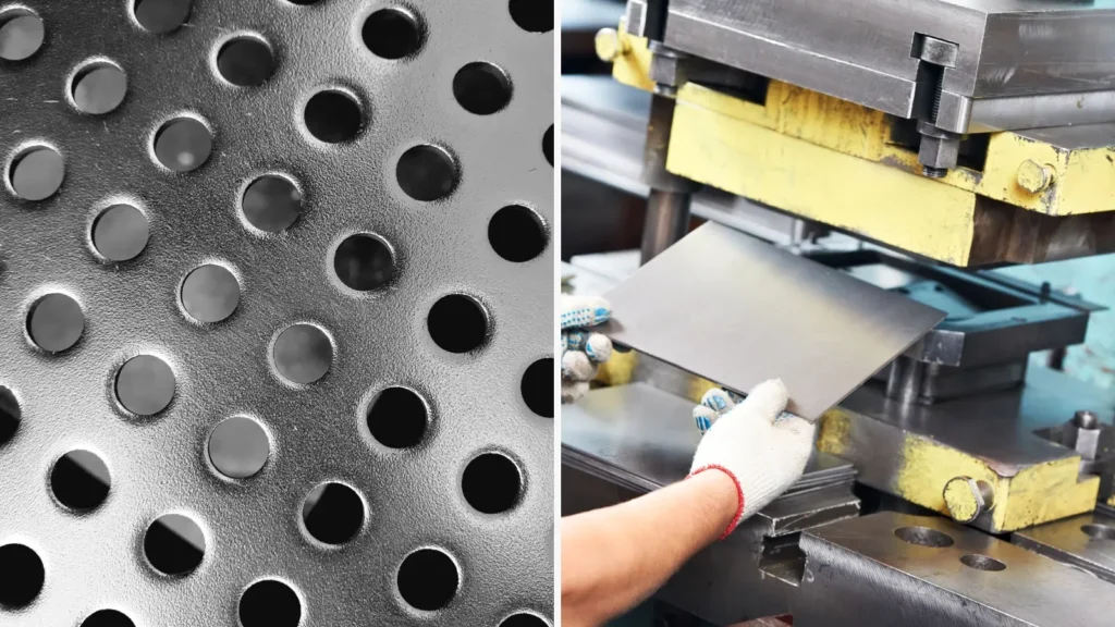
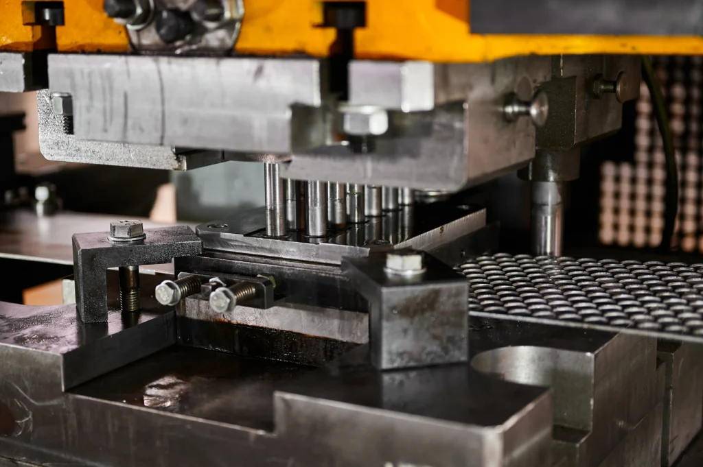
In the highly competitive landscape of automotive and industrial production, global OEM buyers and Tier 1/Tier 2 suppliers are under constant pressure to cut development costs, shorten time-to-market, and mitigate supply chain risks. Tool and die contract manufacturing has emerged as a strategic solution, allowing companies to leverage specialized tooling expertise without heavy capital expenditures. As global supply chains shift toward the “China+1” strategy, Vietnam is rapidly becoming a premier hub for high-precision engineering. As a leading Vietnam tool and die supplier for Europe, North America, and Asia, Automech provides world-class tooling contract manufacturing—delivering advanced progressive dies, transfer dies, and automotive stamping solutions engineered to international standards like ISO 9001 and IATF 16949.
1. Tool and Die Contract Manufacturing: Overview for Global OEM Buyers
1.1 What is tool and die contract manufacturing?
1.1.1 Definition of tool and die contract manufacturing
Tool and die contract manufacturing is a specialized business-to-business (B2B) outsourcing model wherein an OEM or automotive Tier supplier contracts a specialized tooling engineering company to handle the end-to-end realization of custom metal stamping dies, molds, jigs, and precision fixtures. Unlike commodity off-the-shelf component sourcing, contract tooling is a highly customized, engineering-intensive service. The contract manufacturer assumes responsibility for translating 2D part prints and 3D CAD models into fully operational, multi-station tooling systems built to withstand the rigorous forces of high-tonnage mechanical and hydraulic presses over millions of production cycles.
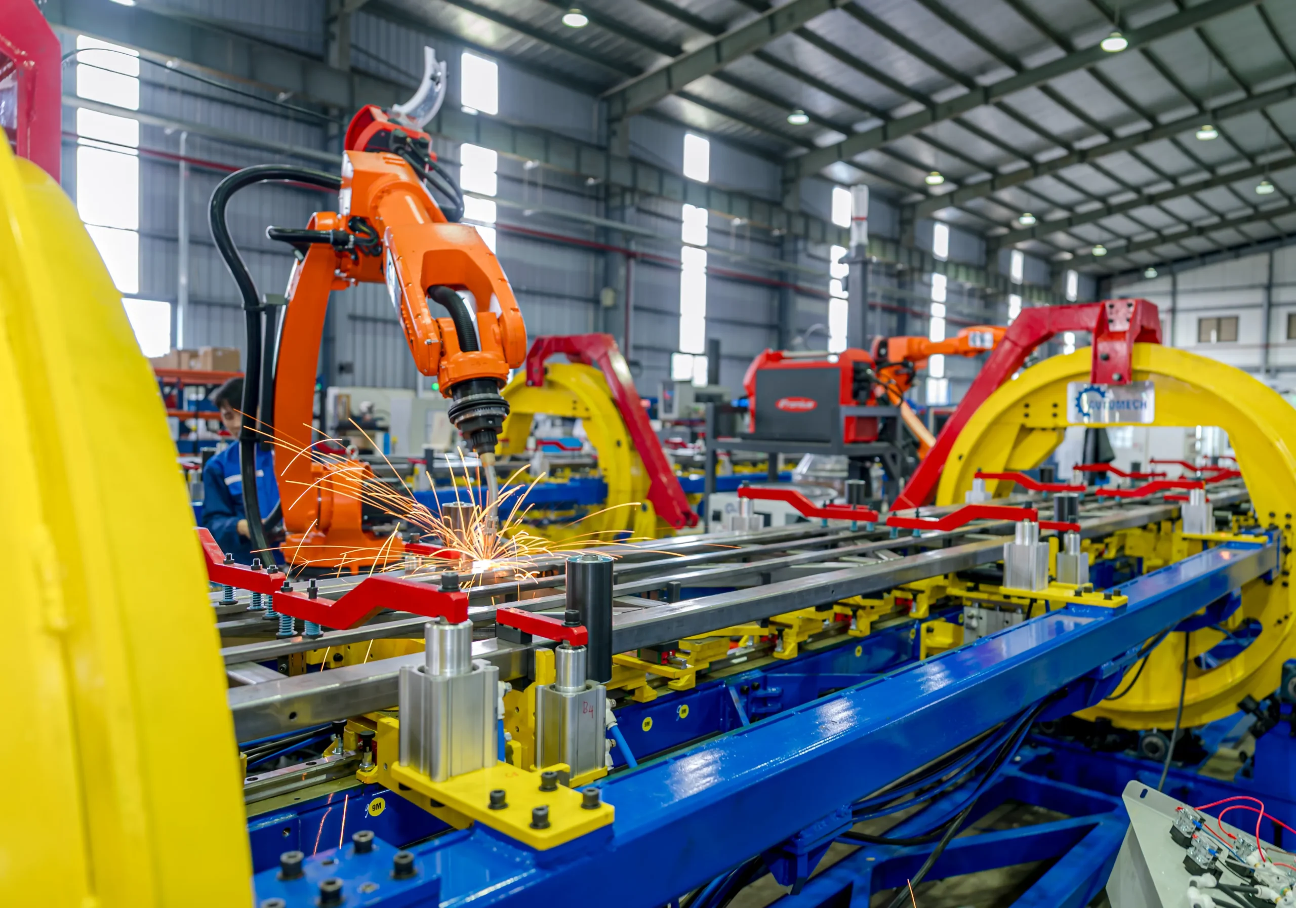
An industrial robotic welding arm performing precision welding on metal frames with sparks flying
1.1.2 Role of outsourced tooling partners in modern manufacturing
In modern industrial ecosystems, outsourced tooling partners function as a direct virtual extension of the buyer’s internal product development and manufacturing engineering departments. Rather than acting as mere “machine shops” that cut steel to customer prints, advanced contract toolmakers provide holistic front-end engineering. They perform critical Design for Manufacturability (DFM) analyses, run Computer-Aided Engineering (CAE) stamping simulations to predict sheet metal behavior, engineer optimal strip layouts, fabricate high-precision die components, and conduct physical press tryouts to validate part dimensions before delivering production-ready dies to the client’s stamping facility.
1.1.3 Difference between tool and die manufacturing and contract tooling services
While the terms are frequently used interchangeably in informal settings, a distinct operational difference exists in an industrial procurement context:
- Traditional Tool and Die Manufacturing: Focuses primarily on the transactional job-shop fabrication of discrete die plates, punches, or basic die sets according to rigid, customer-provided engineering drawings, with minimal involvement in product optimization or long-term production validation.
- Contract Tooling Services: Represents an integrated, long-term strategic partnership encompassing complete lifecycle management. This includes early co-engineering, material flow simulation, press kinematics analysis, tool steel coating selection, First Article Inspection (FAI), full Automotive Production Part Approval Process (PPAP) documentation, on-site press integration support, and scheduled preventive maintenance and spare part replenishment.
1.1.4 Why OEMs outsource tool and die manufacturing instead of building internally
Operating an internal toolroom capable of engineering and building modern Class-A automotive progressive or transfer dies requires millions of dollars in capital investment for large-format 5-axis CNC machines, high-precision Wire EDMs, thermal treatment units, and heavy-tonnage tryout presses. Furthermore, maintaining a full-time staff of specialized die designers, CAE simulation engineers, and master toolmakers creates immense fixed overhead costs that persist regardless of production volumes. Outsourcing tool and die manufacturing enables OEMs to:
- Convert Fixed Capital Expenses (CapEx) into Flexible Variable Costs (OpEx): Capital is preserved for core product R&D, vehicle electrification, and market expansion.
- Mitigate Capacity Bottlenecks: OEM internal toolrooms frequently lack the physical capacity to handle the massive influx of new tooling builds during peak New Product Introduction (NPI) cycles.
- Access Niche Engineering Expertise: Contract toolmakers possess vast experience gathered from building thousands of diverse dies across multiple industries, allowing them to solve complex metal forming challenges faster than isolated in-house teams.
1.2 Importance of tool and die contract manufacturing in automotive and industrial production
1.2.1 Supporting high-volume metal stamping production
Automotive assembly plants operate on precise, high-speed production rhythms where press lines process dozens of stamped panels per minute. High-volume metal stamping demands tooling constructed from ultra-durable tool steels (such as SKD11, DC53, or powder metallurgy steels like ASP23) subjected to specialized heat treatments and physical vapor deposition (PVD) coatings. Contract toolmakers possess the specialized machining capabilities and metallurgical knowledge required to build dies that maintain tight dimensional tolerances (0.02mm) over millions of continuous press strokes without catastrophic tool wear or burr generation.
1.2.2 Reducing tooling investment and manufacturing risks
Developing custom stamping dies carries significant engineering and financial risk. Unanticipated material springback, panel wrinkling, tearing, or severe localized thinning during press trial runs can lead to expensive die modifications, scrapped tool steel, and project delays. Contract tooling specialists mitigate these risks by leveraging sophisticated simulation software like AutoForm and PAM-STAMP. By digitally proving out the metal forming physics prior to cutting steel, contract manufacturers eliminate design flaws early, guaranteeing tooling performance and protecting the buyer’s financial investment.
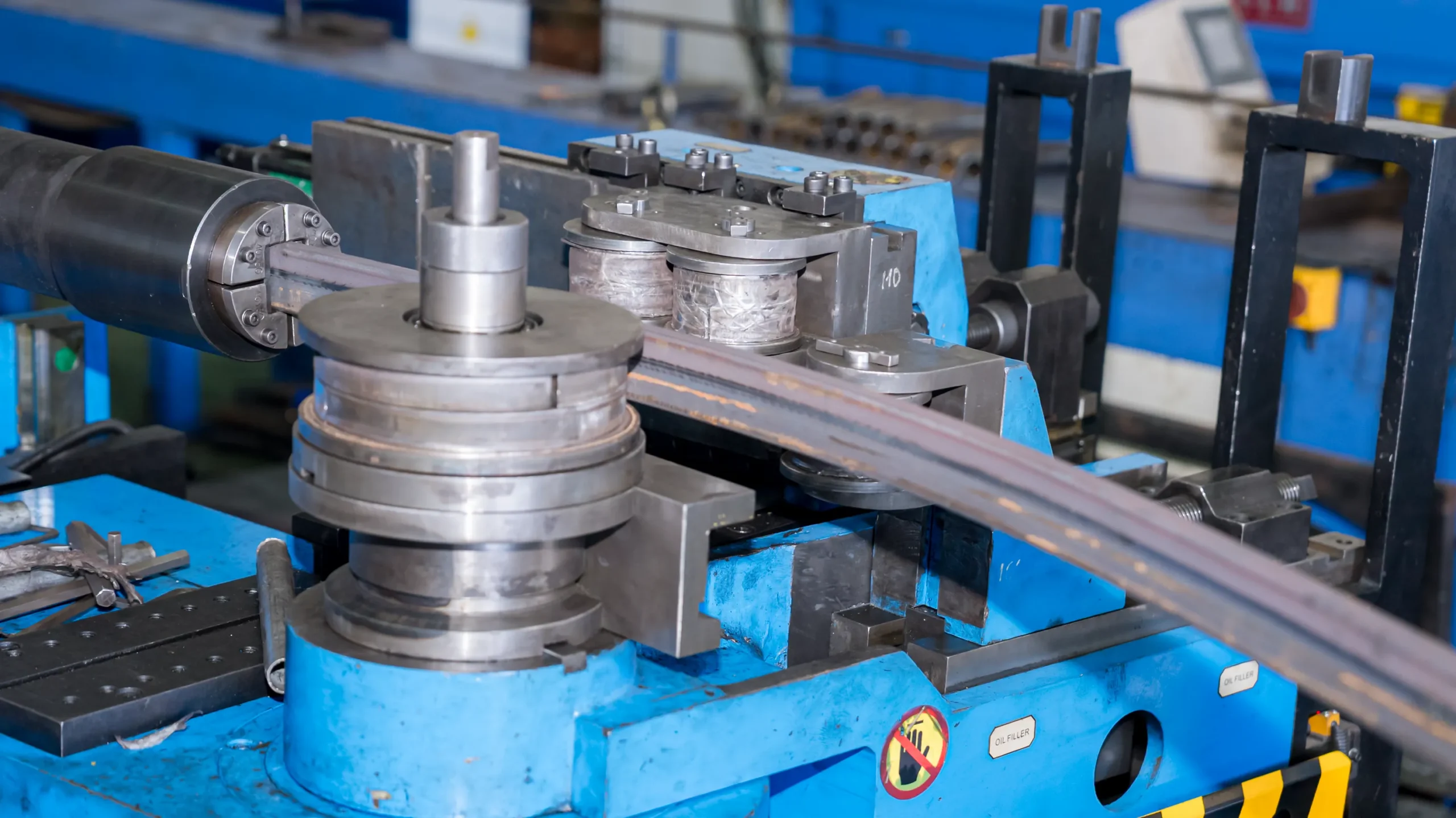
Close-up of an automatic pipe bending machine processing metal square tubes in the workshop
1.2.3 Improving production scalability and supply chain flexibility
Global manufacturers must maintain agile production footprints capable of adapting to changing regional demand, trade policies, and shipping costs. Contract tool manufacturing provides unmatched supply chain flexibility. An OEM can commission complex stamping dies with a high-precision contract manufacturer in Vietnam, validate the tooling through standardized press trials, and export the validated die sets directly to assembly plants in Europe, North America, or Southeast Asia for immediate local production.
1.2.4 Supporting Tier 1 and Tier 2 automotive supplier requirements
Tier 1 and Tier 2 automotive suppliers operate under demanding contracts characterized by tight delivery schedules, strict annual cost-down mandates, and zero-defect quality targets imposed by OEMs. Partnering with a dedicated contract toolmaker allows Tier suppliers to offload the heavy engineering burden of tooling development, ensuring aggressive vehicle program milestones are achieved while securing favorable tooling purchase costs that protect their operating margins.
2. Why OEMs Choose Tool and Die Contract Manufacturing
2.1 Challenges of in-house tooling development
2.1.1 High investment in tooling equipment and engineering resources
Establishing and maintaining a modern, world-class internal toolroom requires immense capital reserves. High-speed 3-axis and 5-axis CNC milling centers capable of cutting hardened tool steels, high-precision Wire and Sinker EDMs, large-bed hydraulic tryout presses (ranging from 500T to over 1500T), and Coordinate Measuring Machines (CMM) represent multi-million-dollar investments. Beyond physical machinery, companies must continually license expensive software suites (UG NX, Catia, AutoForm) and recruit scarce, highly paid master toolmakers and CAD/CAM specialists.
2.1.2 Limited internal capacity for complex die projects
Internal OEM toolrooms are fundamentally sized for steady-state maintenance and minor tool modifications rather than massive new tooling launch programs. When an OEM launches a new vehicle platform requiring dozens of complex progressive and transfer dies simultaneously, internal toolrooms quickly experience severe capacity bottlenecks, leading to delayed trial samples and compromised vehicle production timelines.
2.1.3 Longer development timelines for automotive tooling programs
Because internal toolrooms often handle a wide variety of ad-hoc plant repairs and maintenance tasks alongside new tooling builds, their attention is frequently divided. This lack of single-minded focus—combined with potential gaps in specialized forming expertise for newer materials like Ultra-High-Strength Steels (UHSS)—inevitably leads to extended trial-and-error cycles during die tryout, prolonging overall project lead times.
2.2 Benefits of outsourcing tool and die manufacturing
2.2.1 Access to specialized tooling engineering expertise
Contract tool manufacturing companies focus exclusively on the science and art of die engineering. Their engineering teams possess concentrated experience in metal forming mechanics, strip layout optimization, anti-springback geometry calculation, and advanced die structural design, enabling them to solve complex stamping challenges efficiently.
2.2.2 Lower tooling development costs
By leveraging contract manufacturers located in strategic global engineering hubs like Vietnam, international buyers can capture substantial cost advantages driven by competitive engineering and skilled labor rates, lower facility overheads, and optimized supply chain ecosystems—all without sacrificing dimensional accuracy or tool steel quality.
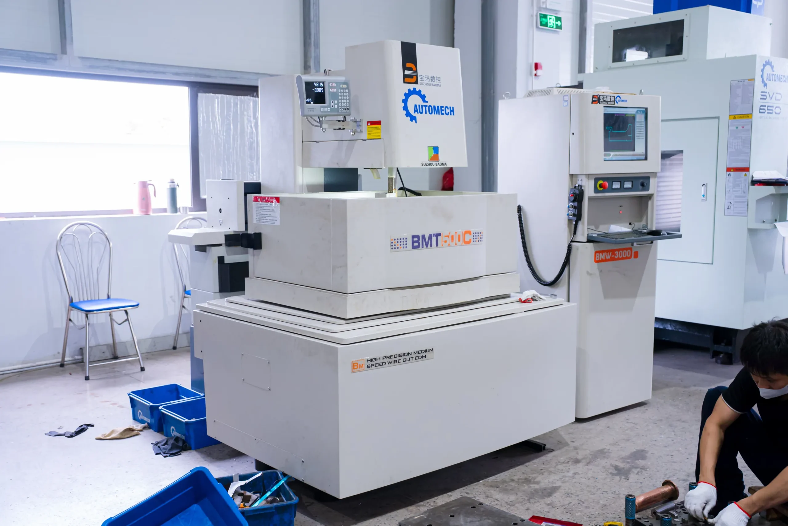
High-precision medium speed wire-cut EDM machine operating in a specialized machining area
2.2.3 Faster prototype and production tooling delivery
Dedicated contract toolmakers structure their operations specifically for rapid project execution. Operating with flexible multi-shift machining schedules, dedicated CAD/CAM workflows, and streamlined internal tryout press availability, contract manufacturers can complete complex die builds and deliver validated T1 sample parts significantly faster than overloaded internal toolrooms.
2.2.4 Improved production readiness and quality control
Before any contract-manufactured die leaves the factory floor, it undergoes rigorous operational validation. Contract toolmakers run extensive tryouts on dedicated press lines, perform 100% CMM dimensional scans, evaluate shear edge burrs, and execute capability studies (Cpk/Ppk) on stamped parts, ensuring the customer receives a fully debugged, production-ready tool that integrates seamlessly into their stamping line.
2.3 Tool and die contract manufacturing vs in-house tooling
| Evaluation Criteria | In-House Tooling Development | Contract Tooling Manufacturing |
| Capital Investment | Very High: Substantial CapEx required for high-speed CNCs, EDMs, and large tryout presses. | Low / Zero CapEx: Tooling costs are capitalized per project without facility overheads. |
| Engineering Capacity | Fixed & Rigid: Vulnerable to severe bottlenecks during major new product launch cycles. | Scalable & Flexible: Easily expands capacity across multiple simultaneous tooling builds. |
| Technology Access | Capital Constrained: Software licenses and machinery upgrades are limited by annual CapEx. | Cutting-Edge: Continuous investment in modern CNC, EDM, software, and simulation tools. |
| Development Risk | 100% Internal Risk: Design errors, recuts, and schedule delays are fully absorbed internally. | Managed Risk: Shared accountability supported by performance guarantees and tryout sign-offs. |
| Cost Structure | High Fixed Costs: Continuous salaries, software maintenance, and machine depreciation. | Variable Project Costs: Clear, transparent pricing tied directly to delivered tooling milestones. |
2.4 Tool and die contract manufacturing vs traditional tool sourcing
2.4.1 Engineering collaboration advantages
Traditional tool sourcing typically follows a transactional “build-to-print” approach, where the vendor passively cuts metal based on customer-supplied drawings without questioning design flaws. Contract tool manufacturing, by contrast, emphasizes early concurrent engineering. The contract partner actively collaborates with the buyer’s design team during the initial concept phase, offering valuable DFM insights that improve part stampability, reduce material scrap, and enhance tool structural integrity.
2.4.2 Manufacturing transparency
Modern contract manufacturing operates on total operational transparency. International buyers receive detailed weekly project progress reports complete with high-resolution photos, video footage of CNC machining and press tryouts, transparent Bill of Materials (BOM) detailing tool steel heat-treat certifications, and open-door policies for in-person or virtual tryout inspections.
2.4.3 Long-term supplier partnership benefits
Establishing a long-term partnership with a contract toolmaker creates powerful operational synergies over time. As the supplier becomes thoroughly familiar with the buyer’s specific press bolsters, shut heights, automated transfer systems, coil feeder setups, and internal quality standards, future tooling programs experience faster kickoff phases, reduced design review cycles, and flawless operational compatibility.
3. Types of Tooling Manufactured Through Contract Manufacturing
3.1 Progressive dies
3.1.1 Progressive die applications in automotive stamping
Progressive dies represent the pinnacle of high-efficiency metal stamping automation. In a progressive die, a continuous strip of sheet metal is uncoiled and fed step-by-step through a series of sequential stations. Each stroke of the press simultaneously performs cutting, piercing, resting, bending, coining, or forming operations across different stations, with the finished component cut free from the carrier strip at the final station. In the automotive sector, progressive dies are widely utilized for manufacturing high-volume brackets, structural clips, electrical connectors, seat belt anchors, and engine bay components.
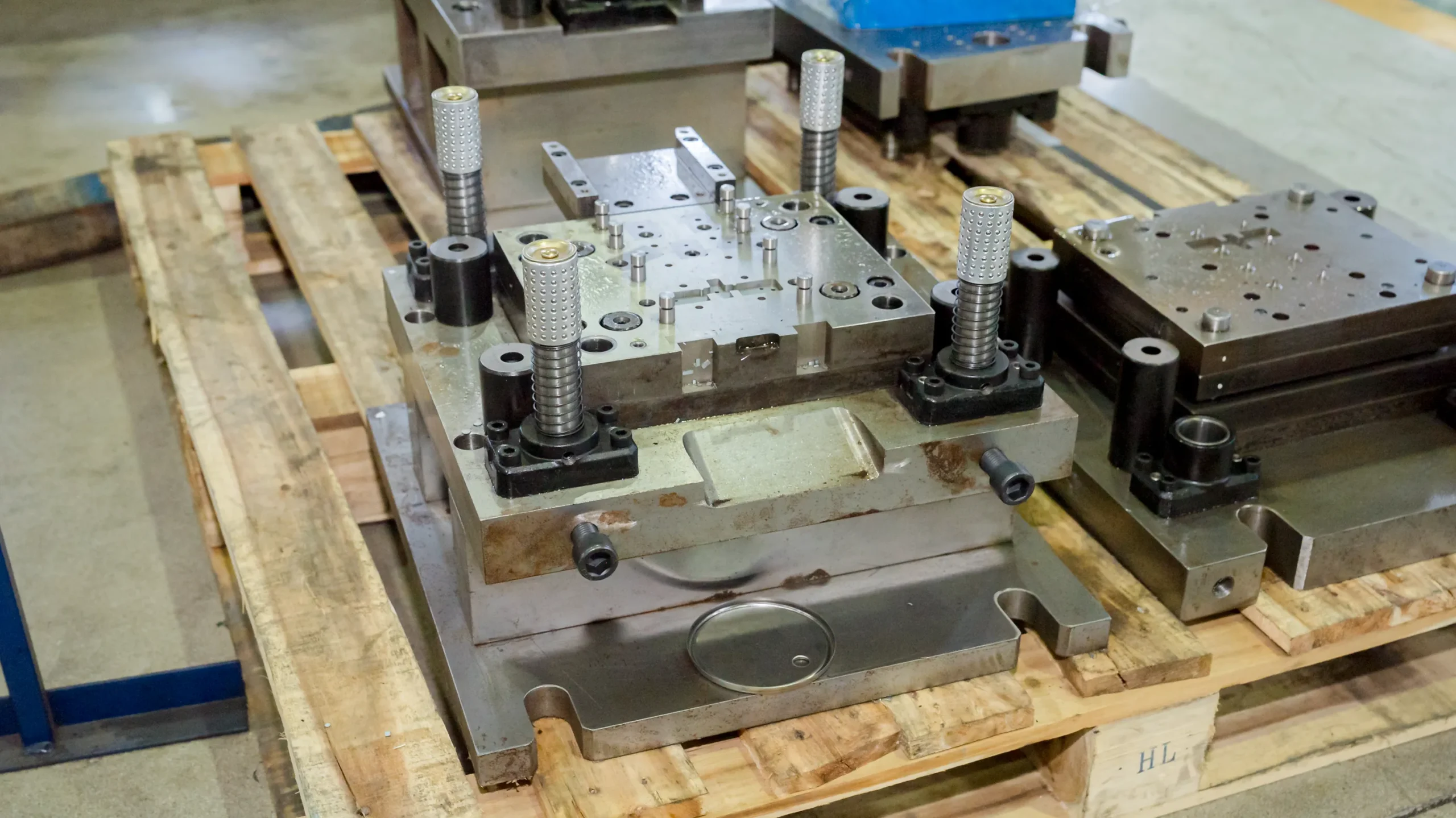
A close-up shot of heavy metal stamping dies placed on a wooden pallet ready for production
3.1.2 High-volume production advantages
- Maximum Press Speeds: Capable of running at high speeds (from 30 to over 200 strokes per minute, depending on part size and complexity).
- Fully Automated Operation: Integrated coil feeding equipment eliminates manual blank handling, dramatically reducing labor costs per part.
- Exceptional Repeatability: Continuous strip guidance via precision pilot pins guarantees consistent part-to-part dimensional accuracy across multi-million part production runs.
3.1.3 Progressive die integration with stamping production lines
Contract toolmakers engineer progressive dies with advanced feature integrations, including automatic stock lifters, mechanical strip guides, pneumatic pitch stops, and integrated sensor blocks (proximity and optical sensors) that connect directly to press control systems to prevent tool damage caused by misfeeds or slug stacking.
3.2 Transfer dies
3.2.1 Transfer die applications for complex automotive parts
Transfer dies are engineered for manufacturing large, heavy-gauge, or geometrically complex components where continuous strip feeding is impossible or material efficiency dictates blanking the material prior to forming. In a transfer press operation, pre-cut sheet metal blanks are automatically picked up and moved from station to station by mechanical or robotic transfer rails equipped with custom finger grippers. Typical automotive applications include body panel reinforcements, door inner frames, oil pans, suspension control arms, and cross members.
3.2.2 Large component manufacturing capabilities
Transfer tooling accommodates large part dimensions and deep-drawn geometries that require complete physical separation between forming operations, allowing complex 3D contouring, trimming, and flanging on all sides of the part.
3.2.3 Transfer tooling design considerations
Designing robust transfer dies requires careful engineering of part clearance envelopes, optimal gripper clearance timing, controlled nitrogen gas spring cushion forces, and vibration damping to ensure smooth, high-speed part movement between die stations without dropped components or surface scratches.
3.3 Compound dies
3.3.1 Multi-operation stamping capability
Compound dies execute multiple cutting or shearing operations—such as simultaneous blanking of the outer profile and piercing of internal holes—in a single press stroke at a single station.
3.3.2 Precision cutting and forming applications
Compound dies are uniquely suited for producing flat, thin, high-precision components that demand exceptional flatness, zero twist, and tight concentricity between internal hole patterns and outer perimeters. Key applications include electric motor laminations, precision transmission shims, clutch plates, and washer discs.
3.3.3 Advantages for specialized stamped components
By completing all cutting actions simultaneously in a single press stroke, compound dies eliminate cumulative pitch errors inherent in multi-station progressive feeding, yielding unmatched geometric precision and clean, burr-free shear edges.
3.4 Single-stage stamping dies
3.4.1 Prototype tooling applications
Single-stage (or line) dies perform a single specific operation per press stroke (e.g., blank only, draw only, trim only, or restrike only). They are extensively used during initial prototype development phases to manufacture low-volume physical test components for crash testing, fitment checks, and vehicle engineering validation.
3.4.2 Low-volume production support
Single-stage tooling offers a highly economical tooling solution for low-volume production applications, such as niche sports cars, heavy commercial trucks, agricultural machinery, and specialized industrial equipment where high-speed automated tooling costs cannot be amortized over low annual volumes.
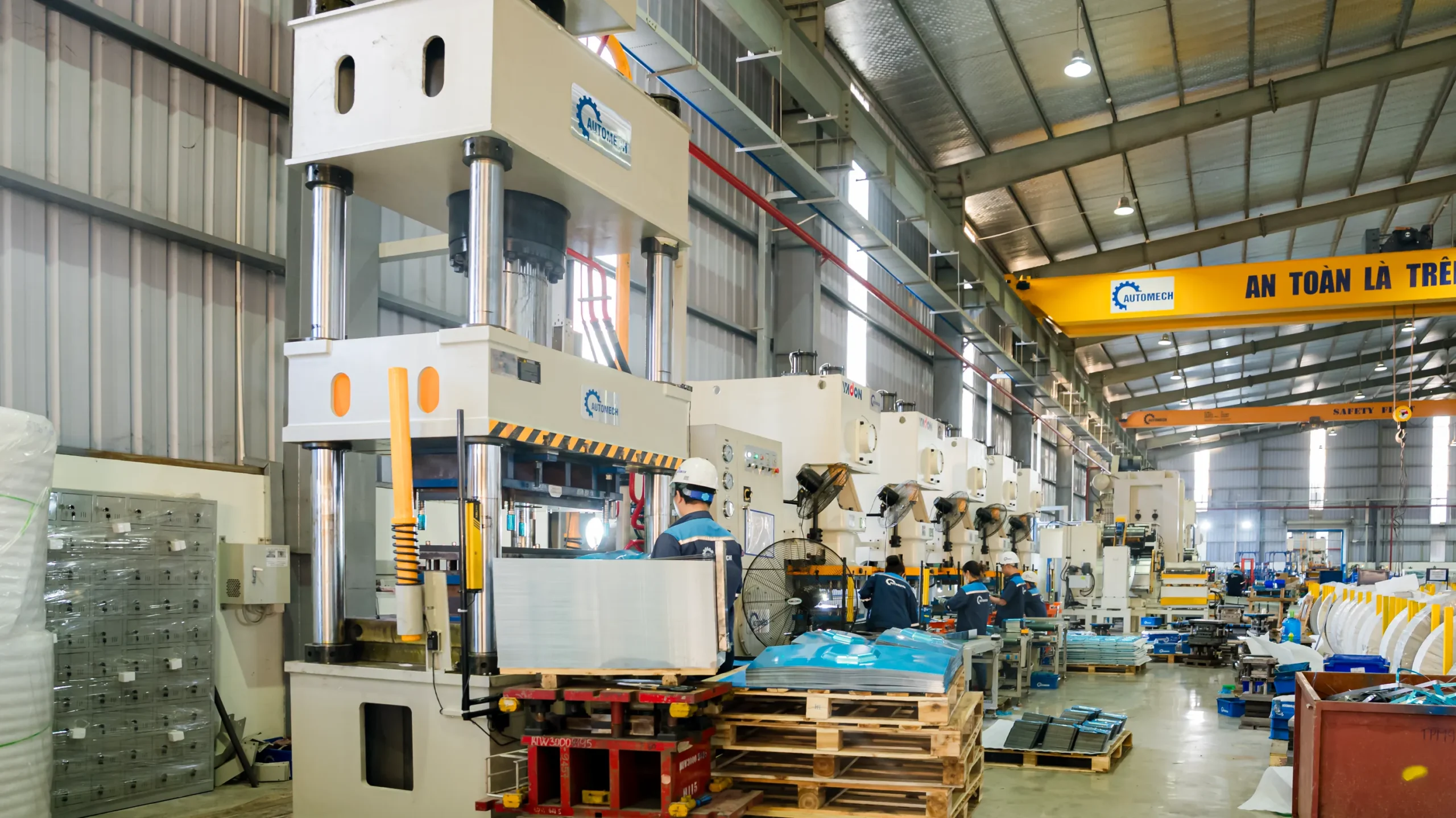
Workers operating heavy hydraulic press machinery along the production line in a large factory bay
3.4.3 Flexible manufacturing solutions
Line dies feature simple, modular die construction that allows quick manual press setups, easy maintenance access, and rapid, low-cost engineering modifications if component designs evolve.
3.5 Automotive production tooling
3.5.1 Automotive stamping dies
Custom-engineered, heavy-duty production tooling specifically constructed to process challenging automotive materials, including Advanced High-Strength Steels (AHSS – DP600, DP800, DP1000), Ultra-High-Strength Steels (UHSS), and lightweight aluminum alloys (5000 and 6000 series).
3.5.2 OEM metal stamping parts tooling
Tooling systems custom-built to comply fully with specific OEM global tooling standards (such as Volkswagen VW 39V, General Motors GMW, Ford W-NX, or Toyota TSM standards), incorporating approved standard components (MISUMI, FIBRO, DAYTON, or DANLY) for global spare parts interchangeability.
3.5.3 Automotive structural component tooling
Extremely durable, heavy-tonnage die assemblies built with reinforced cast-iron or thick forged-steel die shoes designed to handle extreme forming forces encountered when stamping thick structural chassis components, bumper beams, and subframe assemblies.
4. Tool and Die Manufacturing Process
4.1 Product engineering and design review
4.1.1 Customer drawing analysis
The contract manufacturing workflow begins with an exhaustive audit of the buyer’s 2D engineering prints. Engineers scrutinize Geometric Dimensioning and Tolerancing (GD&T) callouts, critical material specifications, grain direction requirements, sheet thickness tolerances, and surface finish expectations.
4.1.2 CAD model evaluation
Importing native 3D CAD geometry into high-end modeling software (UG NX, Catia) allows engineers to inspect draft angles, check bend radii relative to sheet thickness, identify tight internal fillets, and verify surface continuity across complex contoured regions.
4.1.3 Manufacturing feasibility assessment
A formal evaluation to determine whether the requested part geometry can be reliably stamped in a continuous production environment without incurring defects such as split edges, severe thinning, micro-cracking, panel wrinkling, or uncontrollable springback.
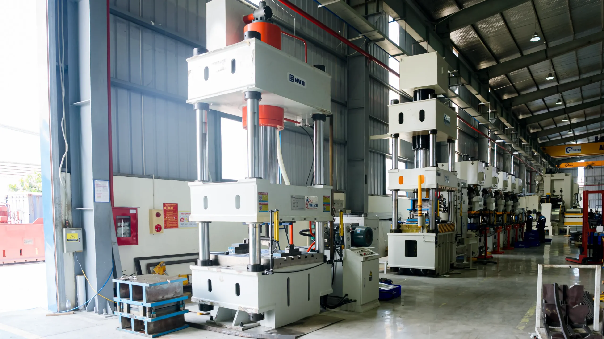
A line of heavy-duty hydraulic press machines installed along the main factory aisle
4.1.4 Design optimization recommendations
When potential manufacturing risks are identified, the contract toolmaker’s engineering team formulates actionable product design modifications—such as slightly increasing a bend radius, adding stiffening ribs, or adjusting hole-to-edge clearances—and presents them to the buyer to optimize stampability without compromising part functionality.
4.2 DFM engineering support
4.2.1 Design for Manufacturing review
A structured engineering methodology focused on analyzing how minor adjustments to component design can significantly simplify die structure, decrease machining complexity, and eliminate unnecessary die stations.
4.2.2 Material flow analysis
Evaluating the physical behavior of sheet metal as it transitions through plastic deformation under high press pressures. Engineers calculate blank holder forces, draw bead placement, and lubricant requirements to maintain uniform material flow into die cavities.
4.2.3 Stamping process optimization
Determining the most efficient operational sequence (e.g., blanking, notch piercing, initial draw, restrike, trim, and final bend) and selecting the optimal press type and tonnage requirement tailored to the buyer’s target production environment.
4.2.4 Cost reduction opportunities
Analyzing strip utilization geometry to maximize the number of stamped parts produced per ton of raw material coil, directly lowering raw material expenditure—which typically accounts for 50% to 70% of the total unit part manufacturing cost.
4.3 CAD/CAM/CAE engineering process
4.3.1 3D die design development
Constructing complete, fully parametric 3D solid models of the entire die assembly in 3D CAD environments. Designers model every detail, including upper and lower die shoes, punch plates, stripper plates, heel blocks, guide posts, nitrogen gas springs, piercing punches, matrix inserts, and stock lifters.
4.3.2 CAM programming for precision machining
Experienced CAM programmers generate high-efficiency CNC toolpaths using advanced software. Toolpaths utilize optimized trochoidal milling, high-speed adaptive roughing, and fine-finish surface strategies to ensure efficient metal removal and superior surface finishes on hardened steel components.
4.3.3 CAE simulation for tooling validation
Running finite element analysis (FEA) simulations using industry-standard packages like AutoForm or PAM-STAMP. The simulation replicates the exact physical stamping process, predicting sheet metal thinning, stress distribution, potential tearing, wrinkling, and springback behavior. The software allows engineers to calculate precise anti-springback geometry directly into the die surfaces before any CNC cutter touches steel.
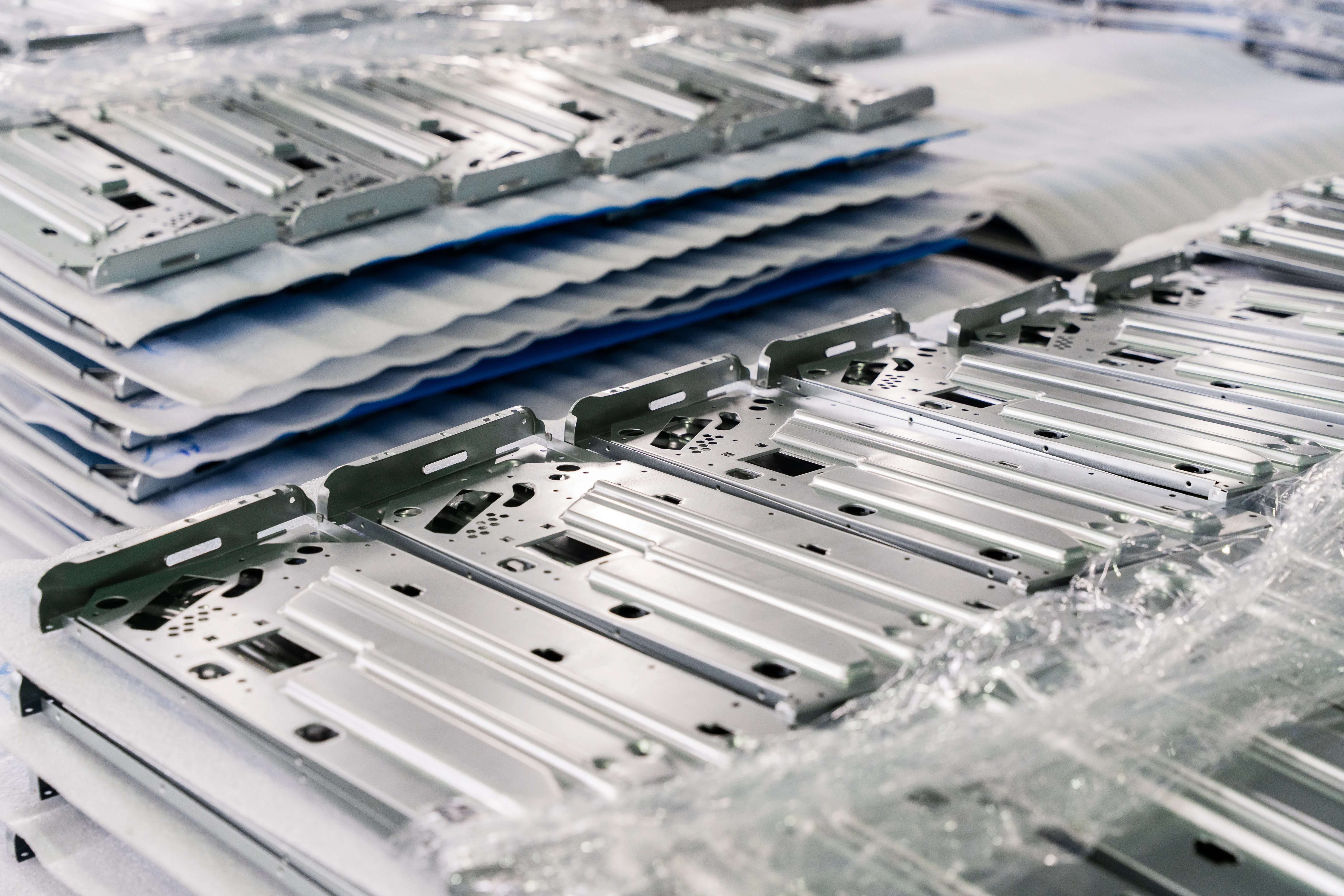
Close-up of a large-scale precision metal mold base with circular cavities for industrial manufacturing
4.3.4 Strip layout optimization
Designing robust progressive die strip layouts that achieve balanced press loading across all stations, maintain carrier strip strength during feeding progression, ensure adequate station-to-station die steel strength, and optimize material pitch distance.
4.4 Tooling material selection
4.4.1 Tool steel requirements for automotive dies
Selecting premium tool steel grades matched to specific operational stresses within the die assembly is essential for ensuring long tool life and preventing premature punch breakage or wear.
4.4.2 SKD11 applications
A widely used cold-work tool steel containing high carbon and high chromium content, offering excellent wear resistance and good dimensional stability after heat treatment (58–60HRC). Ideal for standard blanking inserts, forming dies, and guide components in medium-to-high volume applications.
4.4.3 DC53 applications
An advanced cold-work tool steel that improves upon traditional SKD11. DC53 offers double the toughness, superior fatigue strength, and higher tempered hardness (60–62HRC). It dramatically reduces micro-chipping and cracking on delicate punch tips and heavy-duty forming radii when processing high-strength materials.
4.4.4 ASP23 applications
A high-performance powder metallurgy (PM) tool steel featuring an extremely refined, carbide-rich microstructure. ASP23 provides exceptional compressive strength, outstanding abrasive wear resistance, and high toughness. It is selected for high-stress punches, heavy blanking dies, and ultra-high-volume automotive stamping applications running AHSS/UHSS materials.
4.5 Precision machining process
4.5.1 CNC machining for die components
Utilizing high-rigidity, high-speed 3-axis and 5-axis CNC machining centers to mill die shoes, stripper plates, and complex 3D cavity inserts with structural tolerances maintained within 0.005mm.
4.5.2 Wire EDM machining
Precision Wire Electrical Discharge Machining (Wire EDM) utilizes fine brass wire to cut intricate internal die profiles, keyways, high-precision punch openings, and tight-radius die buttons out of pre-hardened tool steel blocks with sub-micron accuracy and fine surface finishes.
4.5.3 Sinker EDM machining
Using custom-machined copper or graphite electrodes in Sinker EDM units to burn complex, three-dimensional blind cavities, sharp internal corners, embossing features, and deep ribbing directly into hardened steel die plates.
4.5.4 Surface grinding
High-precision surface and profile grinding operations ensure die mounting plates, punch pads, and stripper inserts achieve flat, parallel surfaces (0.003mm parallelism) essential for precise die stack-up alignment.
4.5.5 Jig grinding and precision fitting
Executing ultra-precise grinding of guide pin bushing holes and critical alignment features, followed by meticulous hand-fitting, stone polishing, and alignment check executed by veteran master toolmakers.
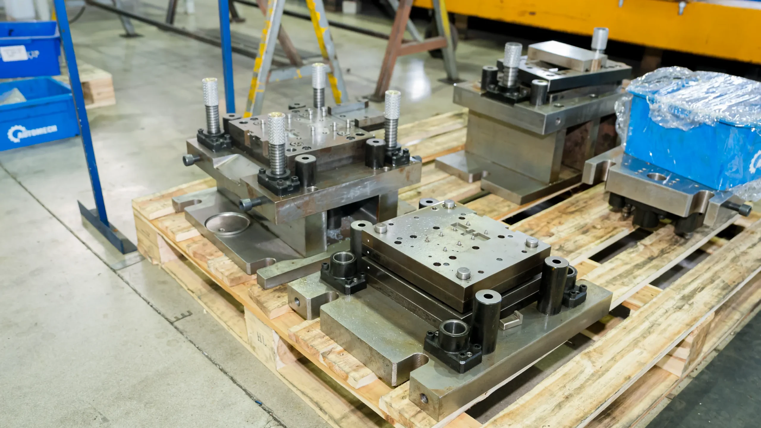
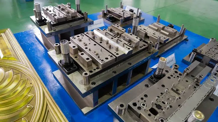
Precision metal stamping dies neatly arranged on wooden pallets in the factory workshop
4.6 Die assembly and validation
4.6.1 Die assembly process
Systematic assembly of ground plates, guide components, nitrogen gas springs, sensor blocks, punches, and die inserts according to strict engineering assembly protocols and torque specifications.
4.6.2 Die spotting process
Applying thin blue fitting ink to die surfaces and mounting the assembled die in a hydraulic spotting press. Toolmakers verify 100% uniform surface contact between upper and lower forming blocks under full clamping force, hand-stoning high spots to achieve smooth metal flow contours.
4.6.3 Tool tryout process
Mounting the assembled die into a mechanical or hydraulic tryout press equipped with automated coil feeding equipment. Engineers feed actual production sheet metal coils through the die at production speeds to evaluate strip feeding balance, stock lifter function, and slug clearance.
4.6.4 Press validation
Inspecting off-tool sample components (T1 samples) for dimensional stability, burr height, edge shear quality, panel springback, and surface finish using optical comparators and CMM equipment.
4.6.5 Production approval
Final sign-off following full CMM dimensional layout reports, 300-to-1000 part continuous run capability studies (Cpk>1.67), customer visual approval, and complete documentation sign-off.
5. Technical Capabilities of a Professional Tool and Die Manufacturer
5.1 Precision tooling engineering
5.1.1 Progressive die design automotive applications
The technical capability to engineer large, multi-station progressive dies exceeding 3 to 4 meters in length, integrating complex side-cam mechanisms, in-die tapping units, and in-die sensor systems for continuous misfeed protection.
5.1.2 Complex stamping die engineering
Mastery over complex plastic metal deformation physics, enabling the design of draw dies, stretch forming dies, and multi-stage flanging tooling capable of processing complex 3D automotive contours without material thinning or cracking.
5.1.3 High precision automotive die manufacturing
Maintaining tight tolerance stack-ups across hundreds of individual precision components within a single die assembly, guaranteeing that replacement wear parts fit perfectly into place without requiring manual fitting at the customer’s factory.
5.2 Advanced machining capabilities
5.2.1 CNC machining accuracy
State-of-the-art high-speed milling equipment housed in climate-controlled machining halls, fitted with optical linear scales and thermal compensation systems to achieve volumetric positional accuracies within 0.003mm.
5.2.2 EDM machining capability
Fine-wire EDM machinery utilizing wire diameters down to 0.1 mm, capable of cutting micro-features, extremely tight corner radii (R0.05mm), and exceptional surface finishes (Ra0.2 m).
5.2.3 Surface finishing requirements
Precision hand-polishing and optical mirror-finishing capabilities achieving surface roughness standards down to Ra<0.05 m on draw dies and forming cavities, preventing material galling, drag marks, and panel scoring during high-speed stamping.
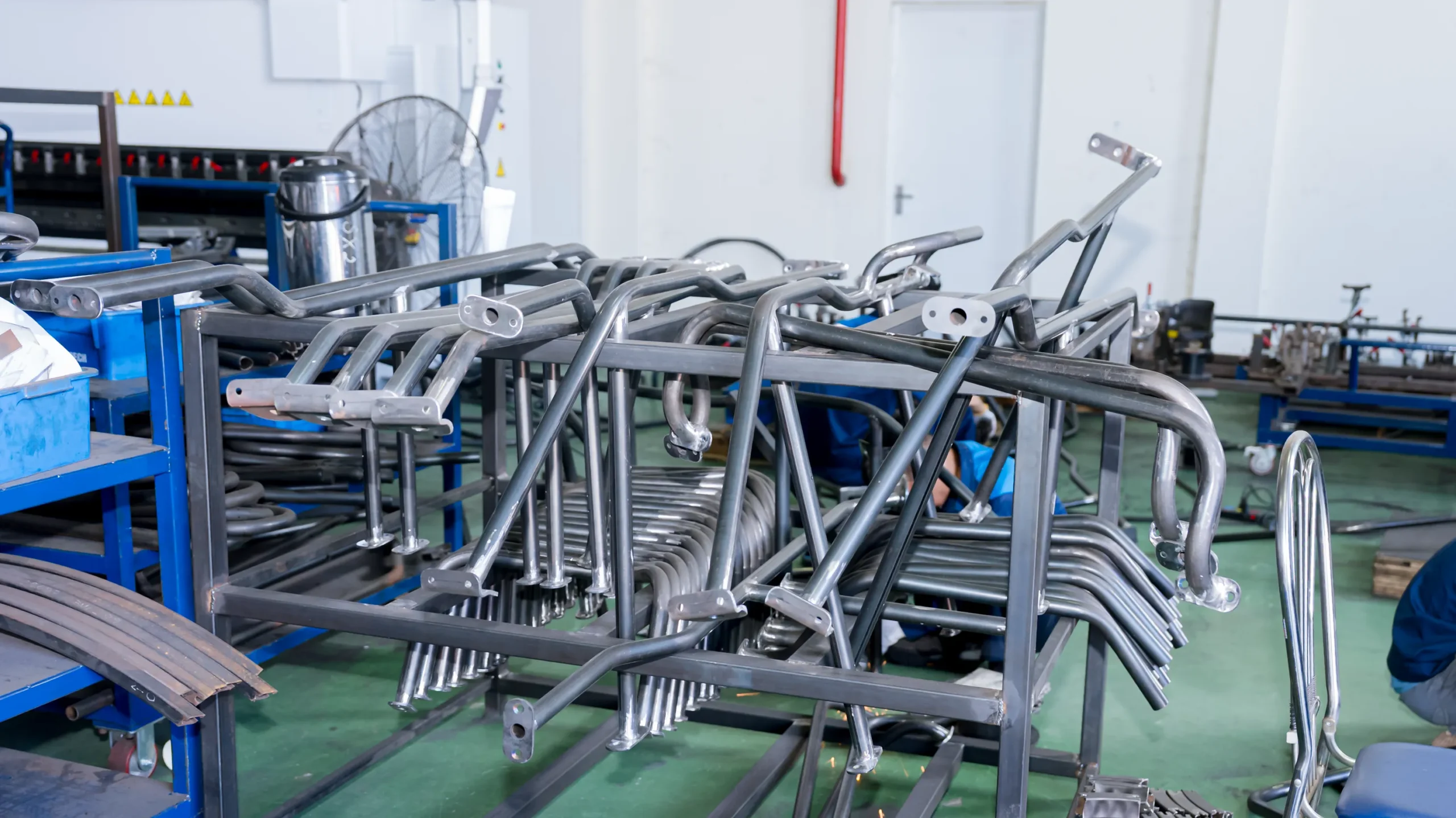
Stacked bent tubular metal components stored on a steel frame rack awaiting assembly
5.2.4 Tight tolerance component manufacturing
Manufacturing core punches, matrix buttons, and guide components to micron-level tolerances, establishing true component standardization and off-the-shelf spare part interchangeability.
5.3 Tool life optimization
5.3.1 Die wear analysis
Conducting systematic wear analysis on returned die components or tryout inserts, using optical microscopy and hardness testing to diagnose root causes of tool degradation, such as abrasive wear, adhesive galling, thermal fatigue cracking, or edge micro-chipping.
5.3.2 Material selection optimization
Upgrading tool steel grades and specifying targeted surface coatings—such as Titanium Aluminum Nitride (TiAlN), Titanium Carbonitride (TiCN), or Thermal Diffusion (TD) processing—to dramatically increase surface hardness (>70HRC) and friction resistance.
5.3.3 Production durability improvement
Optimizing shear cutting clearances, implementing staggered punch heights to reduce total press tonnage impact, and polishing draw radii to extend total die service life up to several million press strokes between maintenance sharpenings.
5.4 Tool maintenance and repair
5.4.1 Preventive maintenance programs
Developing customized, detailed preventive maintenance (PM) manuals, lubrication mapping schedules, and critical inspection checklists pre-packaged with every delivered die to maximize tool lifespan at the customer’s facility.
5.4.2 Automotive stamping die maintenance services
Providing rapid-response technical maintenance, insert sharpening, and re-alignment services for production stamping dies, minimizing costly press line downtime for local and regional stamping plants.
5.4.3 Die repair and refurbishment
Utilizing high-precision laser welding, micro-TIG welding, and precision 5-axis re-machining to repair cracked, chipped, or worn die cavities, restoring damaged tooling back to original 3D CAD engineering specifications.
5.4.4 Spare tooling component replacement
Fabricating and pre-shipping complete sets of high-wear spare parts—including piercing punches, die buttons, pilot pins, stripper inserts, and gas springs—laser-etched with part numbers for quick plug-and-play replacement on the stamping line.
6. Quality Management for Tool and Die Contract Manufacturing
6.1 Quality control systems
6.1.1 Incoming material inspection
Every block of tool steel entering the factory undergoes raw material verification, including optical emission spectrometer chemical analysis, ultrasonic flaw detection to identify internal voids or micro-cracks, and Rockwell hardness testing (HRC) to verify steel mill heat-treat certifications.
6.1.2 Machining process inspection
Implementing strict in-process inspection checkpoints after rough milling, stress-relieving heat treatment, finish grinding, and EDM operations. On-machine optical touch probes automatically verify critical dimensions before components are un-clamped from machining centers.
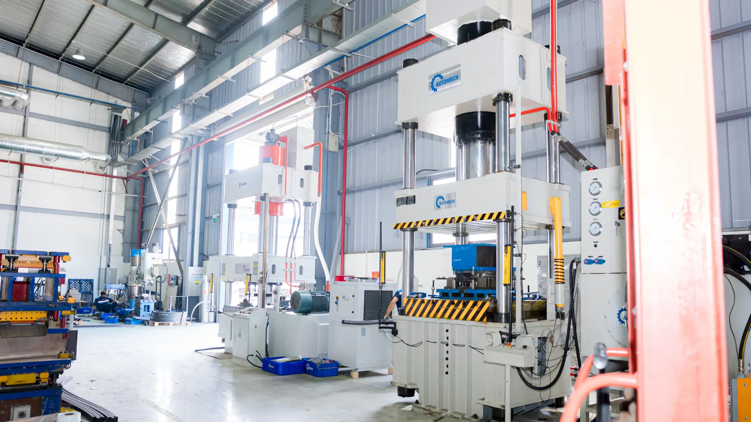
High-tonnage industrial hydraulic press equipment operating inside a spacious manufacturing facility
6.1.3 Final tooling inspection
Executing comprehensive static and dynamic quality audits on fully assembled dies prior to press tryouts. Quality engineers verify shut height, nitrogen gas spring pressures, sensor wiring continuity, safety latch functions, and stroke clearance envelopes.
6.2 Precision measurement systems
6.2.1 CMM inspection
Utilizing high-accuracy CNC Bridge Coordinate Measuring Machines installed in temperature-and-humidity-controlled metrology laboratories to measure complex 3D part profiles, hole locations, and geometric tolerances relative to customer-specified datum schemes.
6.2.2 Optical measurement
Deploying high-resolution 3D non-contact optical blue-light scanners to generate full-field surface mesh scans of off-tool stamped parts. The software overlays the scanned physical part directly against the nominal 3D CAD model, generating color-coded deviation maps that instantly highlight springback or thinning.
6.2.3 Dimensional tolerance verification
Verifying critical geometric dimensions against GD&T callouts, including flatness, position accuracy, profile of a surface, perpendicularity, parallelism, and concentricity.
6.2.4 First Article Inspection (FAI)
Performing rigorous First Article Inspection reports on initial sample components produced during press trials, documenting 100% of print dimensions to guarantee complete drawing compliance.
6.3 Automotive quality requirements
6.3.1 ISO 9001 quality management system
Maintaining certified ISO 9001:2015 quality management systems that govern every operational process, establishing standard operating procedures, complete document control, and continuous process improvement methodologies.
6.3.2 IATF 16949 automotive requirements
Aligning contract manufacturing operations with IATF 16949 automotive quality standards, implementing advanced risk management, strict defect prevention controls, and disciplined product realization protocols required by Tier 1 and OEM automotive customers.
6.3.3 PPAP documentation
Compiling comprehensive Production Part Approval Process (PPAP) Level 1 through Level 5 documentation packages. PPAP packages include full dimensional inspection results, raw material 3.1 chemical/physical mill test reports, heat-treatment certifications, process flow diagrams, control plans, and capability study reports.
6.3.4 APQP planning
Executing Advanced Product Quality Planning (APQP) protocols to systematically manage and track every tooling build milestone from initial contract award through design freeze, machining, assembly, tryout, and final customer approval.
6.3.5 FMEA analysis
Conducting structured Design Failure Mode and Effects Analysis (DFMEA) and Process Failure Mode and Effects Analysis (PFMEA) to identify potential failure modes in tool design or manufacturing processes, establishing proactive corrective actions before fabrication begins.
6.3.6 Control Plan development
Formulating detailed Quality Control Plans that define specific inspection parameters, measurement tools, inspection frequencies, and clear containment protocols for every phase of tooling manufacture and sample validation.
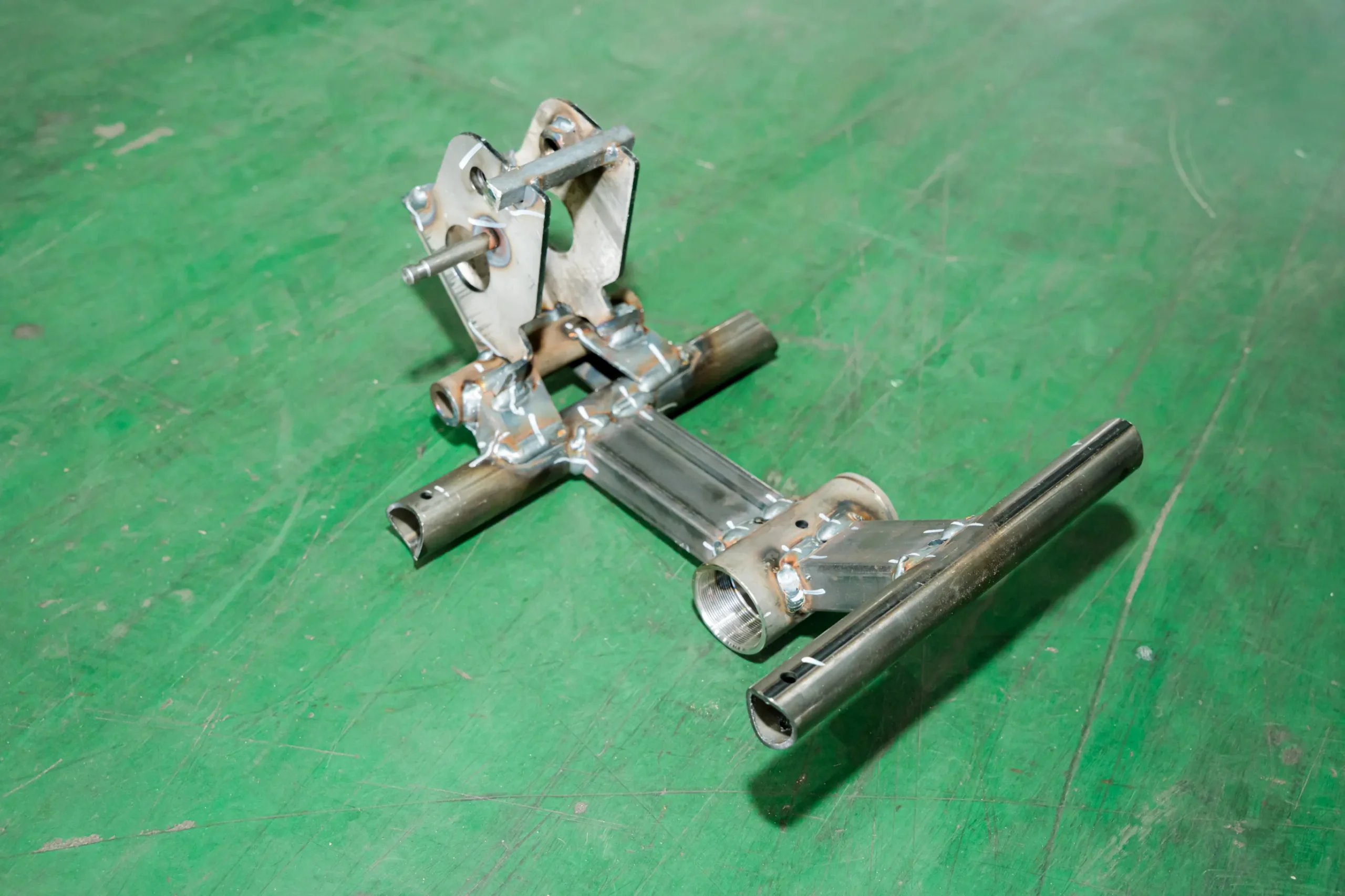
A completed welded tubular steel bracket component placed on the workshop floor for inspection
6.3.7 SPC monitoring
Utilizing Statistical Process Control (SPC) software during continuous sample press runs (300 to 1,000 consecutive strokes) to analyze process stability, calculating process capability indices (Cp,Cpk) and process performance indices (Pp,Ppk) to prove die stability (Cpk>1.67).
6.3.8 MSA validation
Conducting Measurement System Analysis (MSA)—including Gauge Repeatability and Reproducibility (Gage R&R) studies—to verify that all metrology instruments and measurement techniques yield highly precise, repeatable, and operator-independent data.
6.3.9 Production traceability
Maintaining complete material and process traceability. Every structural die plate, insert, punch, and die shoe is permanently laser-etched with unique part identification codes, material heat-lot numbers, and drawing revision levels.
7. Automotive Applications of Tool and Die Contract Manufacturing
7.1 Automotive stamping tooling applications
7.1.1 Body structure components
High-precision stamping dies engineered for Body-in-White (BIW) structural panels, including inner and outer door frames, roof side rails, floor pans, A/B/C pillar reinforcements, hood inner panels, and fender brackets.
7.1.2 Brackets and reinforcement parts
High-speed, multi-station progressive dies designed for producing high-volume brackets, including engine mounting plates, instrument panel supports, seat frame brackets, seatbelt anchor plates, and exhaust system hangers.
7.1.3 Chassis and structural components
Heavy-duty, high-tonnage transfer and line dies built to stamp thick-gauge structural chassis parts, including suspension control arms, trailing arms, subframe cross members, bumper impact beams, and chassis frame gussets.
7.2 Supporting automotive metal stamping production
7.2.1 Progressive die stamping integration
Engineering tooling systems tailored specifically for fast installation and integration into automated tandem press lines equipped with Quick Die Change (QDC) hydraulic clamping plates and standardized utility quick-connects.
7.2.2 Metal stamping tooling support
Providing comprehensive technical support packages, including custom spare part kits, digital 3D CAD models, maintenance manuals, and direct technical consultation for press line troubleshooting.
7.2.3 OEM metal stamping parts manufacturing
Offering complete, flexible contract manufacturing models—ranging from standalone tooling design and build for export to full turnkey contract metal stamping component production within certified press facilities.
7.3 High precision automotive die manufacturing
7.3.1 Tier 1 supplier tooling requirements
Meeting the world-class tooling specifications set by global Tier 1 mega-suppliers (such as Bosch, Continental, Magna, Denso, ZF, and Faurecia), delivering dies built for zero-defect, high-volume production durability.
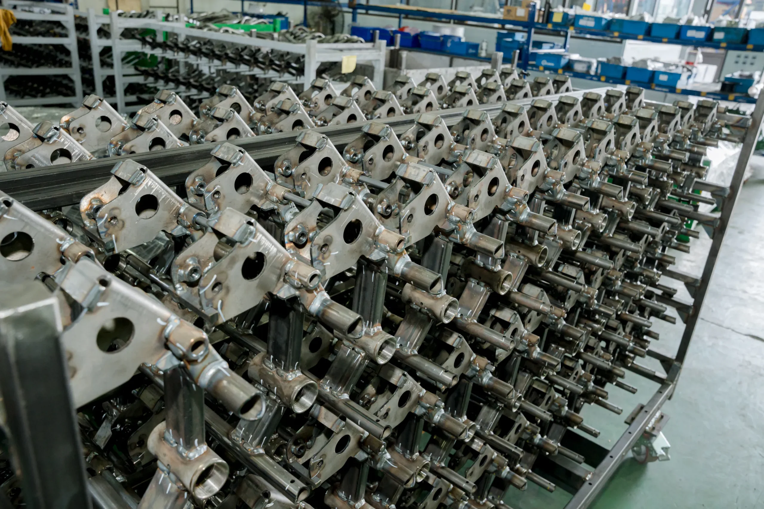
Multiple welded mechanical frame assemblies stacked neatly on mobile storage racks in the plant
7.3.2 Tier 2 supplier manufacturing support
Providing agile, highly cost-competitive tooling solutions for Tier 2 sub-component manufacturers, enabling them to win competitive bids through optimized tooling costs and rapid prototype sample delivery.
7.3.3 Export automotive tooling projects
Demonstrated global export expertise in rust-proofing, vacuum sealing, heavy-duty seaworthy wooden crating, and managing international sea/air logistics to deliver large die sets directly to stamping plants across Europe, the Americas, and Asia.
8. Automotive Tooling Export and Vietnam Manufacturing Advantages
8.1 Why choose Vietnam for tool and die contract manufacturing
8.1.1 Competitive tooling manufacturing costs
Vietnam offers an exceptionally attractive cost-to-quality ratio for complex engineering services. International buyers leveraging Vietnamese contract toolmakers routinely achieve a 20% to 35% overall reduction in tooling procurement costs compared to Western Europe, North America, or mainland China, driven by competitive skilled engineering labor, efficient overhead structures, and favorable tax regimes.
8.1.2 Growing automotive supporting industry
Supported by robust domestic market growth (driven by automakers like VinFast) and massive Foreign Direct Investment (FDI) from international automotive giants (Toyota, Honda, Hyundai), Vietnam has built an extensive supporting industry ecosystem. This network includes certified tool steel distributors, specialized commercial heat-treatment centers, PVD coating facilities, and precision hardware suppliers.
8.1.3 Skilled tooling engineering workforce
Vietnam boasts a large, highly motivated, and technically skilled workforce. Vietnamese technical universities graduate thousands of mechanical, metallurgical, and mechatronic engineers annually who are highly proficient in modern 3D CAD/CAM/CAE platforms, high-speed CNC programming, and precision metrology.
8.1.4 Strategic China+1 sourcing advantage
As global OEMs actively restructure their supply chains to build resilience against geopolitical friction, unilateral tariffs, and regional supply disruptions, Vietnam has emerged as the premier “China+1” manufacturing hub. Vietnam offers seamless geographic connectivity to Asian raw material supply chains, excellent deep-water port infrastructure, political stability, and an open, export-oriented economic environment.
8.2 Vietnam tool and die supplier capabilities
8.2.1 Tool and die export manufacturer
Leading Vietnamese contract manufacturers have successfully transitioned into world-class export suppliers, adopting modern Western and Japanese manufacturing philosophies, strict quality control protocols, and customer-focused project management.
8.2.2 Automotive tooling export Asia
Supplying high-precision stamping dies and contract components to major automotive manufacturing hubs throughout Japan, South Korea, Thailand, Indonesia, and India.
8.2.3 Vietnam tool and die supplier for Europe
Leveraging the landmark EU-Vietnam Free Trade Agreement (EVFTA), Vietnamese tooling suppliers offer European buyers significant competitive advantages. EVFTA eliminates or drastically reduces import tariffs on mechanical tooling and components, streamlines customs procedures, and provides robust legal protections for intellectual property.
8.2.4 Global OEM supply chain support
Equipped with fluent English-speaking technical project managers, digital progress tracking portals, real-time video tryout streaming, and complete compliance with international trade documentation, Vietnamese suppliers ensure seamless collaboration with overseas engineering teams.
8.3 Vietnam vs traditional tooling sourcing markets
| Strategic Factor | Western Europe / USA | Mainland China | Vietnam (Automech) |
| Tooling Cost | Extremely High: Heavy labor rates and overheads. | Moderate: Rising labor and operational costs. | Highly Competitive: 20% to 35% overall cost savings. |
| Import Tariffs (EU/US) | Standard: Zero domestic tariffs but high initial cost. | High Tariffs: Subject to punitive trade tariffs/duties. | Preferential: Duty exemptions via EVFTA / CPTPP. |
| Supply Chain Risk | Low Risk: Geographically close but capital intensive. | High Risk: Geopolitical & trade concentration risk. | Low Risk: Ideal “China+1” diversification choice. |
| Engineering Quality | Excellent: High precision and mature standards. | Variable: Quality ranges from low to high grade. | High Precision: Certified ISO 9001 / IATF compliant. |
| IP Protection | Strong Legal Safeguards: Well-established IP framework. | IP Concerns: Continuing IP enforcement risks. | Strong Protection: Robust contractual & legal IP laws. |
9. Automotive Die Cost Optimization
9.1 Factors affecting tooling costs
9.1.1 Die complexity
Tooling costs scale directly with part geometry complexity, total linear dimensions, the number of required forming stations, and the incorporation of complex mechanical side-cams, uncoiling units, or in-die tapping mechanisms.
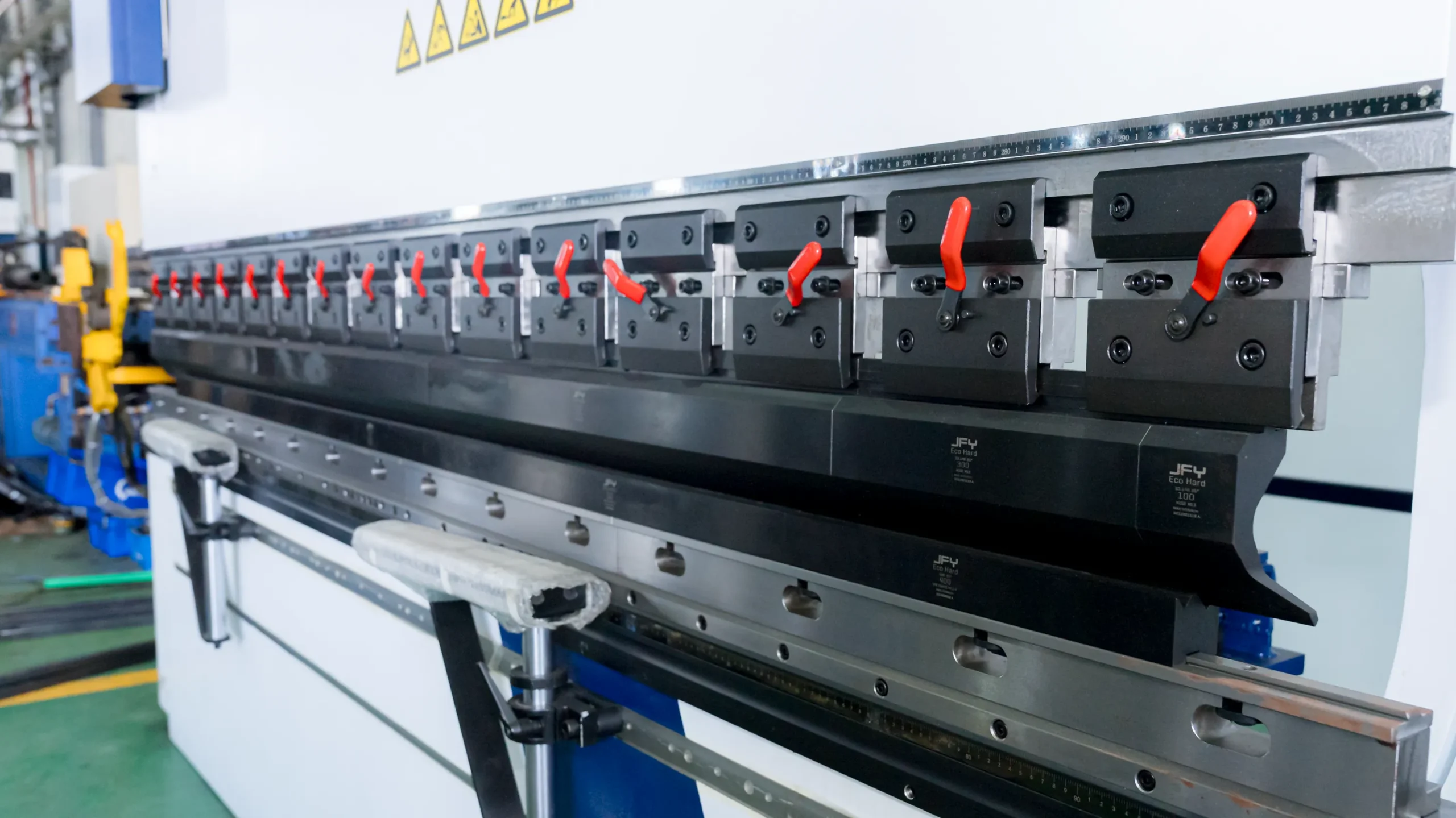
Close-up view of the clamping system and tooling bed of a JFY CNC press brake machine
9.1.2 Material selection
Selecting premium powder metallurgy tool steels (ASP23) or applying advanced PVD surface coatings increases upfront raw material costs. However, these advanced materials yield a significantly lower total cost per part over long, high-volume production runs by preventing premature die failure and reducing maintenance downtime.
9.1.3 Production volume requirements
Prototype or pre-series programs with low lifetime volume requirements (<50,000 parts) can be produced using lower-cost soft tooling or single-stage line dies. High-volume programs (>1,000,000 parts) necessitate hardened, fully automated progressive or transfer dies.
9.1.4 Tool life expectations
Designing a die set for a service life of 100,000 strokes requires far less structural steel, simpler guide components, and standard tool steel grades compared to a Class-A automotive die engineered to run 3,000,000+ strokes under aggressive production press conditions.
9.2 Cost reduction strategies
9.2.1 Progressive die optimization
Combining multiple standalone manual press operations into a single, high-speed progressive die dramatically cuts labor costs, reduces work-in-progress (WIP) inventory, and decreases floor space requirements.
9.2.2 Material utilization improvement
Optimizing nesting geometry, strip orientation angle, and pitch spacing during the strip layout design phase increases sheet metal material utilization efficiency, saving substantial raw material costs over the life of the program.
9.2.3 Process simplification
Refining the forming sequence through advanced CAE simulation allows engineers to eliminate superfluous idle stations or consolidate multiple forming passes into a single engineered die station without sacrificing dimensional quality.
9.2.4 Tool life improvement
Applying specialized surface engineering—such as localized nitriding, PVD coatings, or micro-polishing on high-friction forming radii—extends punch and insert life, reducing re-sharpening frequency and downtime.
9.3 Engineering-driven cost optimization
9.3.1 DFM review
Conducting rigorous DFM reviews prior to design freeze allows engineers to identify and eliminate costly design features—such as excessively tight internal radiuses or unnecessary tight non-critical tolerances—before steel machining begins.
9.3.2 Design modification recommendations
Proactively recommending minor modifications to non-functional part geometry, such as enlarging hole-to-bend clearance gaps or relaxing non-mating dimensions, simplifies die construction and reduces machining hours.
9.3.3 Manufacturing process improvement
Utilizing high-speed 5-axis CNC hard milling to cut hardened tool steels directly (>60HRC) eliminates labor-intensive, time-consuming electrode fabrication, sinker EDM processing, and manual bench polishing.
10. How to Choose a Tool and Die Contract Manufacturer
10.1 Supplier evaluation criteria
10.1.1 Tooling engineering capability
Verify that the supplier maintains an in-house engineering department staffed by experienced die designers and simulation experts proficient in 3D CAD (UG NX/Catia) and finite element metal forming software (AutoForm/PAM-STAMP).
10.1.2 Manufacturing equipment
Audit the manufacturer’s machinery fleet to ensure they operate modern, high-precision equipment: 3/5-axis CNC machining centers, precision Wire EDMs, surface grinders, climate-controlled inspection rooms, and adequate-tonnage trial press lines with automated feeders.
10.1.3 Quality certifications
Ensure the contract manufacturer holds valid, accredited quality management certifications, including ISO 9001:2015, and demonstrates full operational alignment or formal certification with IATF 16949 for automotive programs.
10.1.4 Automotive experience
Evaluate the supplier’s track record in producing tooling for international Tier 1 and Tier 2 automotive programs, requesting verified case studies, PPAP sample documentation, and export references to global markets.
10.2 Technical qualification checklist
- Engineering Software: Full in-house CAD/CAM integration, 3D parametric die design, and incremental AutoForm metal forming simulation.
- Machining Precision: CNC volumetric positioning accuracy within 0.005mm; Wire EDM micro-finish capabilities.
- Metrology Laboratory: Climate-controlled inspection room featuring CMM, 3D blue-light optical scanning, and optical comparators.
- Press Tryout Infrastructure: On-site hydraulic and mechanical tryout presses (minimum 300T to 1000T+) equipped with automated coil feeders and decoilers for production-speed validation.
10.3 RFQ process for tool and die manufacturing
10.3.1 Submit CAD drawings
Provide complete 2D engineering drawings (with clear GD&T callouts) and 3D CAD part models in standard exchange formats (STEP, IGES, Parasolid).
10.3.2 Provide tooling specifications
Include explicit tooling guidelines: annual part volumes, material specifications (grade, thickness, mechanical properties), available press specification sheets (tonnage, stroke, shut height, bolster size, cushion data), target tool life, and required standard component brands (MISUMI, FIBRO, DAYTON).
10.3.3 Engineering feasibility review
The contract toolmaker conducts a preliminary DFM, strip layout, and CAE forming simulation to confirm component stampability and formulate an optimized tooling proposal.
10.3.4 Tooling quotation
The buyer receives a formal, itemized commercial and technical quotation outlining die design fees, material costs, machining hours, press tryout charges, CMM inspection fees, seaworthy packing, export logistics, and a detailed Gantt chart schedule.
10.3.5 Production approval process
Upon commercial agreement, signing NDAs, and contract execution, the engineering teams initiate formal design reviews, culminating in a 3D CAD design freeze and approval to order tool steel.
11. Tool and Die Contract Manufacturing Partner in Vietnam – Automech
11.1 Automech tooling manufacturing capability
11.1.1 Custom die manufacturing expertise
Automech is a leading engineering and contract manufacturing company located in Vietnam, specializing in high-precision tool and die solutions for global automotive, industrial, consumer appliance, and electronics manufacturers.
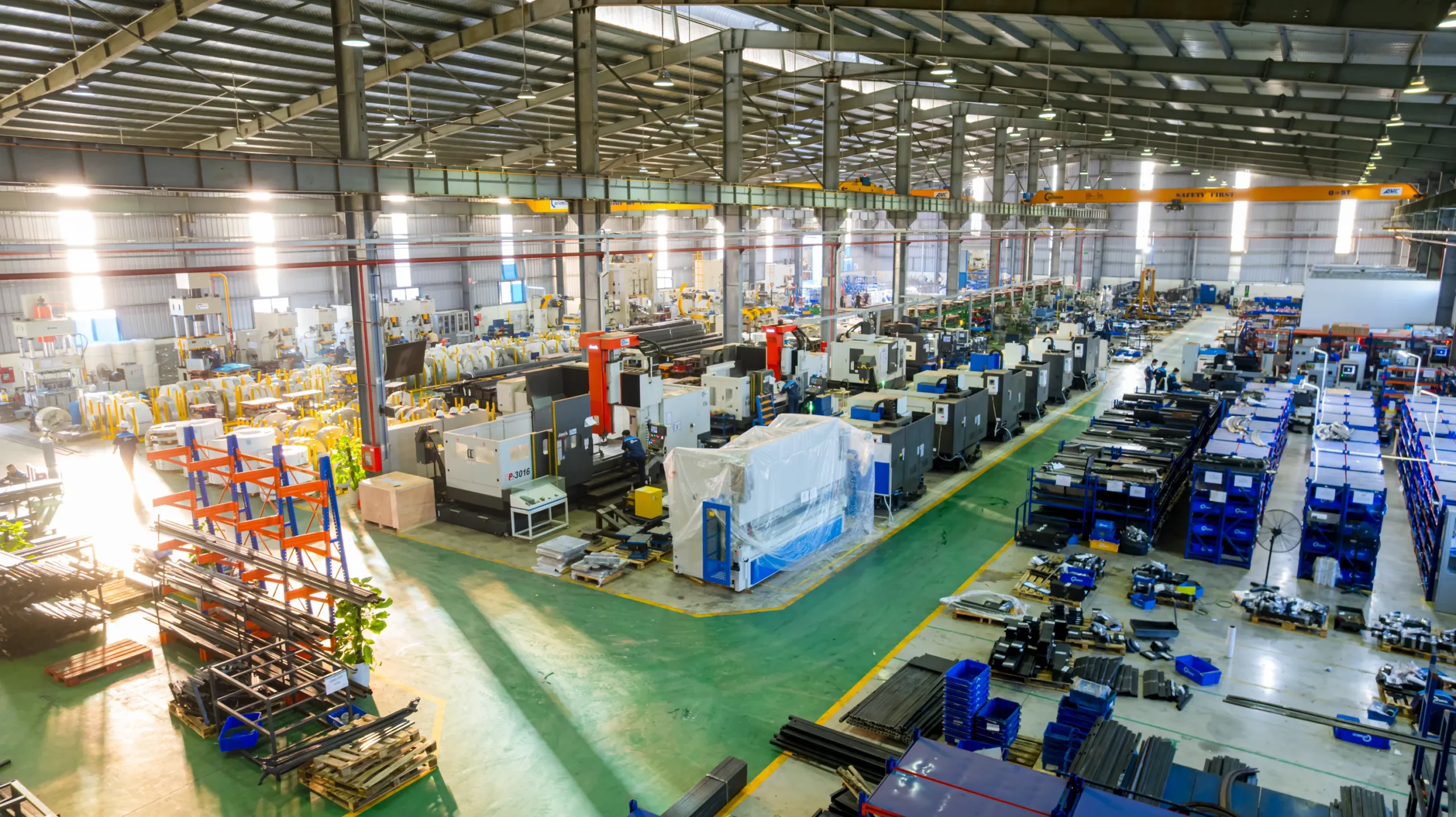
Panoramic high-angle view of a large-scale manufacturing plant with various machinery and organized material racks
11.1.2 Tool and die contract manufacturing capability
We deliver complete, turnkey contract tooling services—managing the full product realization cycle from initial concept review, DFM optimization, and 3D CAD die design to precision CNC/EDM machining, master toolmaker assembly, tryout press validation, and series stamping supply.
11.1.3 Automotive tooling experience
Automech brings deep experience partnering with Tier 1 and Tier 2 suppliers globally, engineering rugged tooling systems for critical structural body parts, engine brackets, interior frame components, and precision chassis stampings.
11.1.4 Progressive die manufacturing capability
We specialize in high-speed, multi-station progressive dies engineered for exceptional durability, ultra-tight tolerances, and effortless, plug-and-play integration into automated high-speed stamping press lines.
11.2 Engineering and manufacturing support
11.2.1 CAD/CAM engineering
Our dedicated engineering department utilizes high-end design platforms (UG NX, Catia) to build fully parametric 3D die assemblies engineered strictly in accordance with client-specific tooling guidelines and international standards.
11.2.2 DFM review
We provide comprehensive Design for Manufacturability (DFM) analysis reports alongside every quotation, helping buyers uncover part design optimizations that eliminate manufacturing risks and reduce total tooling costs.
11.2.3 Tool design optimization
Utilizing state-of-the-art metal forming simulation software (AutoForm), our simulation engineers perform rigorous sheet metal formability, springback, and thinning analyses, perfecting die geometry prior to steel cutting.
11.2.4 Tool tryout and validation
Our manufacturing facility features dedicated hydraulic and mechanical tryout presses equipped with automated coil feeding equipment, allowing us to perform continuous, production-speed press trials and deliver fully validated T1 sample parts.
11.3 Production and export capability
11.3.1 Prototype tooling
Offering agile single-stage and soft tooling packages for fast-turnaround prototype component manufacturing and engineering validation.
11.3.2 Pilot tooling
Engineering pre-series pilot dies designed to support vehicle build trials, assembly line commissioning, and early market launch volumes.
11.3.3 Production tooling
Class-A high-volume production tooling constructed with premium tool steel grades (DC53, SKD11, ASP23) and specialized PVD coatings, engineered to deliver multi-million stroke service lives.
11.3.4 Export projects for US/EU markets
Automech possesses proven expertise exporting complex, heavy tooling systems to European and North American destinations. We execute comprehensive export preparation, including VCI anti-corrosion coating, vacuum sealing, seaworthy wooden crating, and complete export customs clearance documentation under EVFTA frameworks.
11.4 Quality assurance capability
11.4.1 Quality inspection systems
Strict quality control checkpoints govern every manufacturing phase—raw material receiving inspection with optical spectrometers, in-process CNC touch-probe verification, heat-treatment hardness testing, and CMM final inspection.
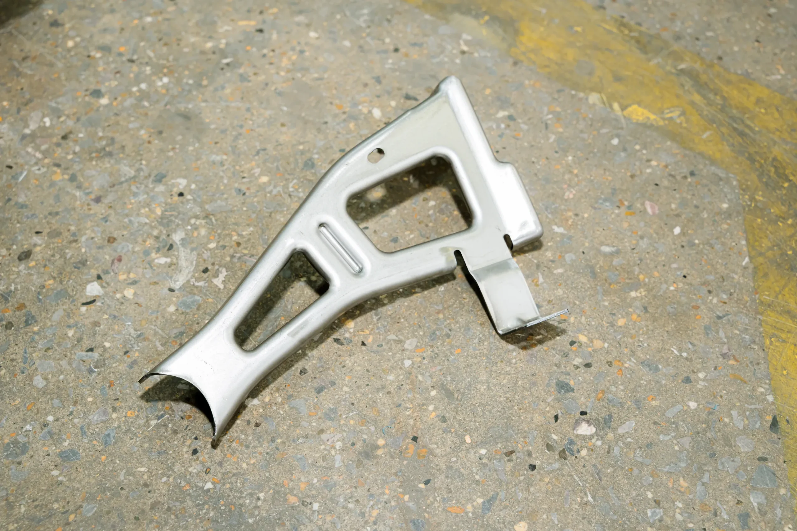
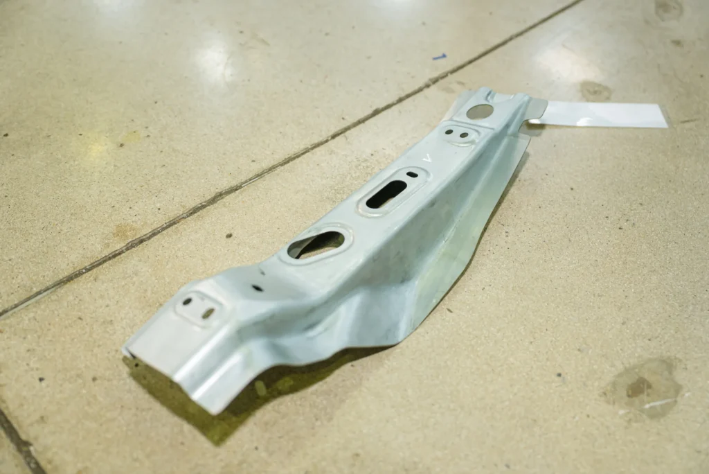
A stamped metal structural component featuring mounting holes and reinforcement ribs
11.4.2 ISO 9001 compliance
Operating under certified ISO 9001:2015 quality management systems, ensuring total operational repeatability, standardized manufacturing workflows, and complete engineering traceability.
11.4.3 IATF 16949 compliance
Our quality management framework is fully structured to satisfy IATF 16949 requirements, delivering complete PPAP Level 1–5 documentation, APQP milestone tracking, PFMEA risk analyses, and SPC process capability verification (Cpk>1.67).
11.4.4 Automotive documentation support
Every export die set is delivered with a comprehensive quality package: 3D CAD data, 2D assembly prints, CMM dimensional reports, material 3.1 certificates, heat-treatment logs, maintenance manuals, and laser-etched spare parts lists.
12. FAQ: Tool and Die Contract Manufacturing
12.1 What is tool and die contract manufacturing?
It is a strategic business model where an OEM or industrial buyer contracts a specialized external tooling manufacturer to design, engineer, machine, assemble, and validate custom stamping dies and tooling systems, eliminating the need to maintain an expensive internal toolroom.
12.2 Why do OEM companies outsource tool and die manufacturing?
OEMs outsource to reduce capital expenditure on expensive machinery, lower tooling acquisition costs, access specialized DFM and forming simulation expertise, eliminate internal toolroom bottlenecks, and scale production capacity flexibly.
12.3 What types of dies can contract manufacturers produce?
Contract manufacturers produce a full range of metal stamping dies, including high-speed progressive dies, transfer dies, compound dies, deep-draw dies, and single-stage prototype dies for diverse industrial applications.
12.4 What industries use tool and die contract manufacturing?
While the automotive sector (BIW, chassis, structural parts) is the primary consumer, contract tooling is heavily utilized in aerospace, consumer electronics, home appliances, medical devices, renewable energy, and heavy equipment manufacturing.
12.5 What certifications should a tool and die supplier have?
A qualified supplier must hold ISO 9001:2015 quality management certification at a minimum and demonstrate operational compliance or formal certification with IATF 16949 for automotive tooling programs, supported by complete PPAP documentation capabilities.
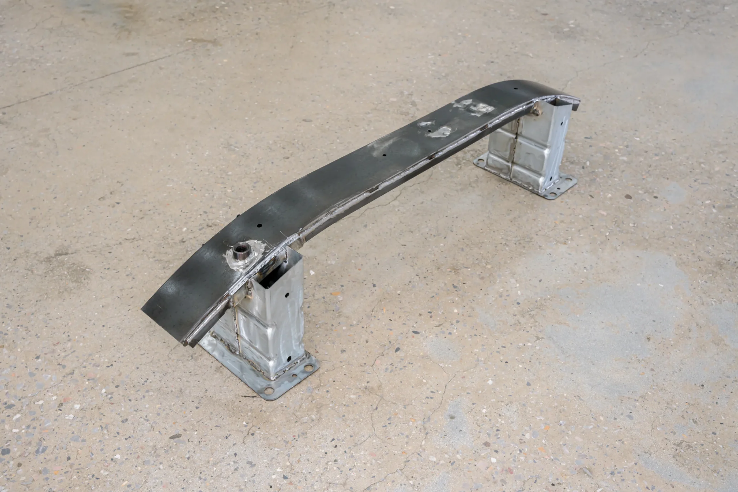
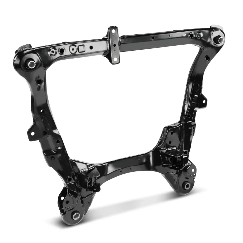
A heavy-duty welded steel bumper beam crossmember assembly placed on the concrete floor
12.6 How long does custom tooling manufacturing take?
Lead times vary based on die size and station complexity. Prototype and single-stage dies typically take 4 to 8 weeks, while complex Class-A progressive or transfer dies take 12 to 20 weeks from 3D design freeze to final T1 sample sign-off.
12.7 How do I request a tool and die manufacturing RFQ?
To request a detailed RFQ, submit your 2D drawings (with GD&T), 3D part CAD files (STEP/IGES), material specifications, annual part production volumes, and press specification sheets directly to the Automech engineering team.
Automech Mechanical Equipment and Solutions Joint Stock Company
Head Office: No. 285 Phuc Loi Street, Phuc Loi Ward, Hanoi City
Da Nang Branch: No. 20 Nguyen Sinh Sac Street, Hoa Khanh Ward, Da Nang City
Ho Chi Minh Branch: No. 84, Street No. 10, Van Phuc Urban Area, Hiep Binh Ward, Ho Chi Minh City
Factory No. 1: Automech Automation Equipment, Mold & Tool Manufacturing Factory – Automech Demo Center: Dinh Tram Industrial Park, Nenh Ward, Bac Ninh City, Vietnam
Factory No. 2: Automech Parts Manufacturing & Component Fabrication Factory: Viet Nhat Industrial Cluster, Xuan Cam Commune, Bac Ninh City, Vietnam
Hotline: 0902 997 331
Website: https://automechmfg.com/
Fanpage: https://www.facebook.com/automech.mfg/
YouTube: https://www.youtube.com/@Automechmfg