OEM metal stamping parts represent the foundation of modern discrete manufacturing, providing custom, high-volume sheet metal components manufactured strictly to original equipment manufacturer (OEM) specifications. Across global automotive platforms, industrial machinery systems, electronics, and energy infrastructure, OEMs rely on dedicated contract stamping partners to transform flat metal coils into complex structural brackets, reinforcement plates, precision enclosures, and functional sub-assemblies. By combining engineering design reviews, precision tool and die making, automated mechanical and servo press lines, and certified quality management systems, OEM metal stamping delivers repeatable dimensional accuracy, controlled structural integrity, and low unit costs at mass-production scale.
1. OEM Metal Stamping Parts: Definition and OEM Manufacturing Scope
1.1 What Are OEM Metal Stamping Parts?
1.1.1 Definition of OEM metal stamping parts
OEM metal stamping parts are custom-engineered metal components produced by a contract stamping manufacturer specifically for integration into an Original Equipment Manufacturer’s finished product, vehicle, or machinery assembly. These parts are cold-formed from sheet metal coils or flat blanks using dedicated press tooling, conforming to proprietary design requirements rather than generic market configurations.
1.1.2 How OEM stamped parts are designed to customer specifications
Unlike standard off-the-shelf catalog hardware, OEM stamped parts are fabricated strictly according to the customer’s proprietary 2D engineering drawings, 3D CAD models, material callouts, and performance criteria. Every geometric feature-including hole centers, flange bend angles, embossed stiffening ribs, and surface finishes-is tailored to interface seamlessly with mating components in the customer’s final product architecture.
1.1.3 OEM parts vs aftermarket and standard stamped components
OEM stamped parts differ fundamentally from aftermarket replacements and standard commercial components. Standard catalog stampings use generic dies with wide dimensional tolerances and universal mounting features. Aftermarket components are often reverse-engineered with variable material consistency. In contrast, OEM stamped components utilize dedicated, customer-approved tooling, adhere to strict raw material mill specifications, undergo rigorous validation processes, and carry full production traceability.
1.2 What Makes an OEM Metal Stamping Part Different?
1.2.1 Customer-specific drawings, CAD data, and specifications
OEM manufacturing requires exact adherence to customer digital models (STEP, IGES) and fully dimensioned 2D drawings. Toolmakers engineer stamping dies directly from this nominal CAD geometry, ensuring that every geometric dimensioning and tolerancing (GD&T) datum, true position, and profile callout is replicated accurately on the shop floor.
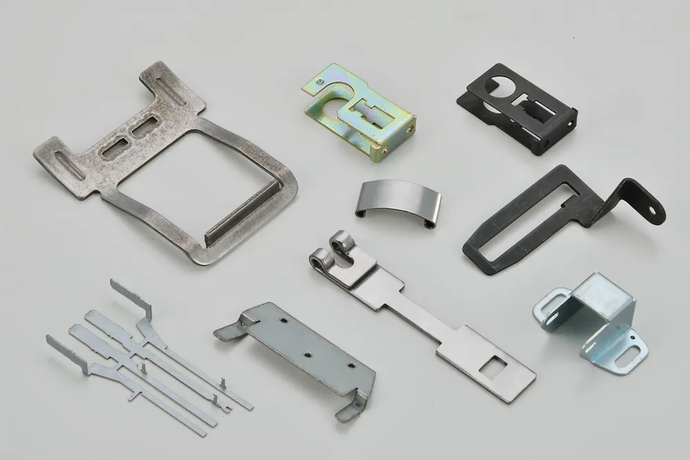
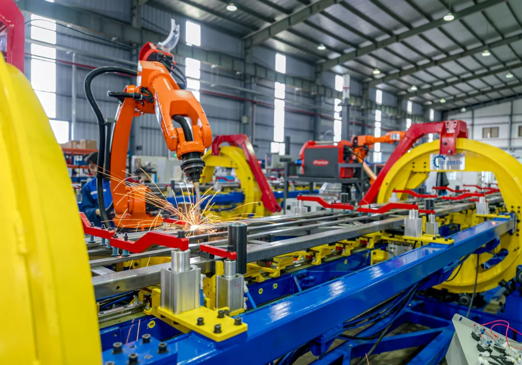
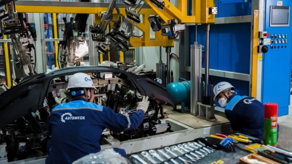
By combining modern press automation with custom tooling, Automech delivers superior OEM metal stamping parts worldwide
1.2.2 Material, tolerance, dimensional, and surface-finish requirements
OEM specifications mandate tight control over physical and chemical properties. Contracts define allowable raw material grades, coil thickness tolerances, tensile strength ranges, micro-inch surface roughness limits (Ra), maximum allowable burr heights, and protective plating specifications (such as zinc plating, E-coating, or anodizing).
1.2.3 Tooling ownership and production control
In OEM contract stamping, the customer typically finances and owns the proprietary stamping dies, while the contract manufacturer maintains, stores, and operates the tooling exclusively for that customer’s orders. Production cannot be altered without a formal Engineering Change Notification (ECN) approved by the OEM engineering team.
1.2.4 Quality documentation and traceability
OEM parts demand comprehensive quality verification. Suppliers must provide advanced documentation packages-such as Advanced Product Quality Planning (APQP), Production Part Approval Process (PPAP) submissions, Failure Mode and Effects Analysis (FMEA), Control Plans, and raw material Mill Test Reports (MTR)-along with multi-year batch traceability linking finished components to master coil heat numbers.
1.2.5 Prototype-to-mass-production capability
A qualified OEM stamping partner supports the entire component lifecycle. This includes providing rapid soft-tool prototypes for physical fitment testing, supporting pilot pre-series runs for assembly line validation, and scaling seamlessly into automated high-volume mass production.
1.3 OEM Metal Stamping Applications
1.3.1 Automotive OEM components
Automotive vehicle platforms represent the largest consumer of OEM stamped parts, utilizing custom stampings for body-in-white (BIW) safety structures, floor pan crossmembers, door intrusion reinforcements, electric vehicle (EV) battery enclosures, and seating mechanisms.
1.3.2 Industrial equipment components
Heavy machinery, fluid pumps, electrical generators, agricultural machinery, and commercial HVAC equipment incorporate custom OEM stamped brackets, motor mounting plates, vibration baffles, fan housings, and protective sheet metal guards.
1.3.3 Structural and functional sheet metal parts
OEM stampings fulfill both load-bearing structural roles and functional mechanical roles. They serve as chassis subframe connectors, cabinet structural pillars, electrical shielding cans, heat dissipation shields, and kinematic latch mechanisms.
1.3.4 Brackets, reinforcements, and mounting components
Brackets and mounting plates represent the most versatile family of OEM stampings. Engineered with compound bends, coined edges, and precision-pierced fastener holes, these components align and secure critical sub-systems across demanding operational environments.
2. OEM Metal Stamping Manufacturing Process
2.1 Engineering and DFM Review
2.1.1 Technical drawing and CAD review
The manufacturing sequence begins with an in-depth evaluation of the customer’s 2D drawings and 3D CAD data. Engineering teams evaluate geometric datums, critical assembly interfaces, surface callouts, and drawing notes to establish clear manufacturing parameters.
2.1.2 Material and thickness verification
Engineers analyze the specified metal alloy, temper, and gauge thickness to confirm that the material possesses sufficient elongation and formability for the intended geometries without exceeding ultimate tensile limits during forming.
2.1.3 Tolerance and manufacturability analysis
Designers cross-reference specified tolerances against standard pressworking capabilities. Identifying non-critical dimensions with excessively tight tolerances allows engineers to propose adjustments that prevent unnecessary tooling complexity and lower piece-part costs.
2.1.4 DFM and cost optimization
Design for Manufacturability (DFM) reviews optimize part geometries for press production. Engineers recommend standardizing bend radii, modifying piercing hole spacings to at least twice material thickness, increasing hole-to-edge distances, and designing blank silhouettes that maximize sheet nesting efficiency.
2.1.5 Prototype and tooling feasibility assessment
Utilizing finite element metal forming simulation software, engineers evaluate sheet metal flow, localized thinning, wrinkling risks, and springback behavior. This digital simulation validates tooling feasibility before physical tool steel is cut.
2.2 Stamping Process
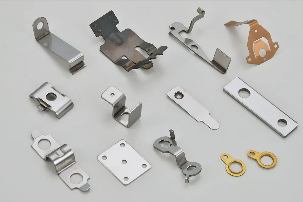
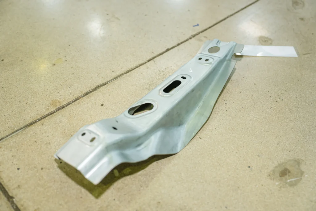
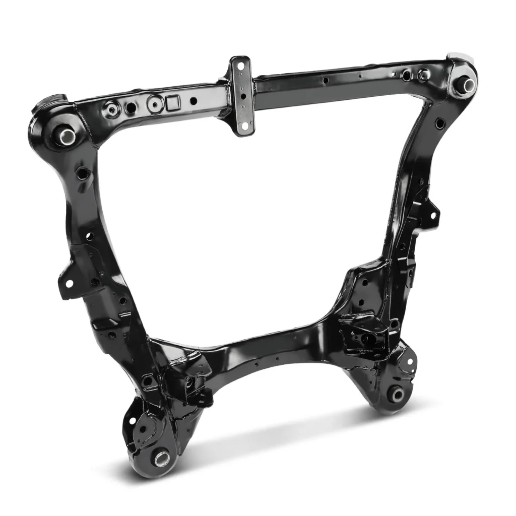
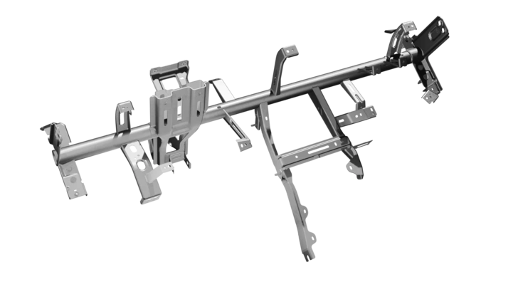
Rigid chassis brackets and engine mounts are essential OEM metal stamping parts in modern vehicle manufacturing
2.2.1 Blanking
Blanking shears the outer perimeter silhouette of a part from continuous metal coil or flat sheet stock. The sheared blank serves as the primary workpiece for subsequent bending, forming, or drawing stages.
2.2.2 Piercing
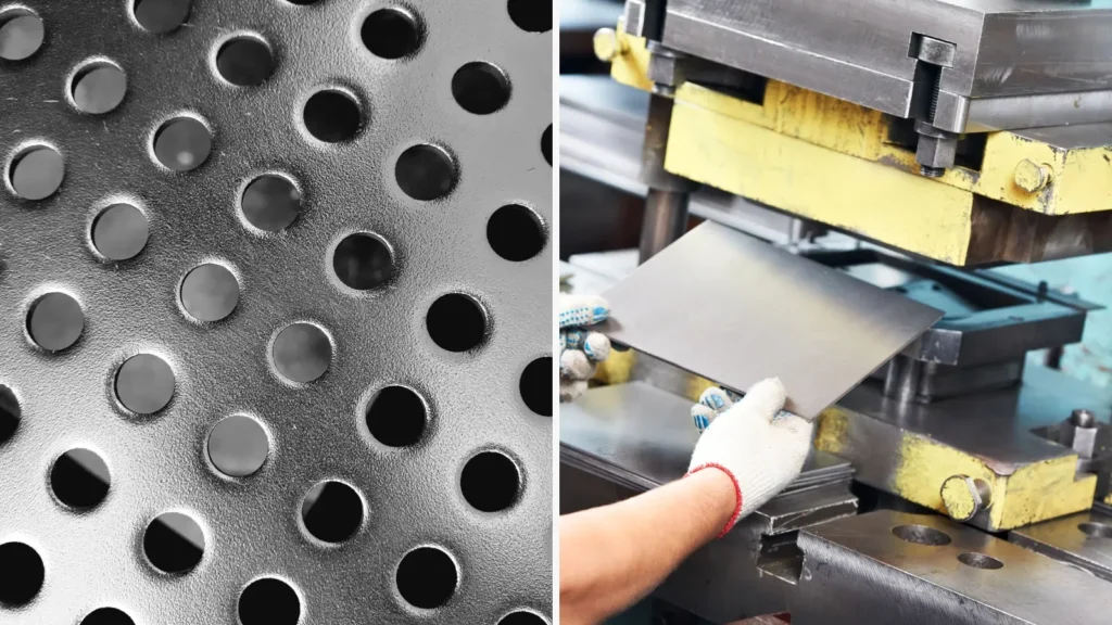
Piercing punches holes, slots, and interior cutouts through the sheet metal. Precision punches enter female die openings, ejecting scrap slugs downward through relief passages to prevent slug pull-up defects.
2.2.3 Bending
Bending deforms flat sheet metal plastically along a linear axis to create angles, channels, and mounting flanges. Toolmakers incorporate calculated over-bending angles and coining features into forming dies to counteract elastic springback.
2.2.4 Forming
Forming deforms sheet metal along non-linear, contoured, or compound axes without shearing material fibers. This operation produces structural stiffening beads, embossed identification codes, offset joggles, and contoured flanges that increase rigidity.
2.2.5 Drawing and deep drawing
Drawing forces flat sheet metal into female die cavities using a mechanical punch. When the depth of the resulting recess exceeds its opening width, the process is classified as deep drawing, forming seamless motor covers, fluid reservoirs, and battery module cans.
2.2.6 Precision stamping
Precision stamping utilizes tight punch-to-die clearances (< 5% of material thickness per side), rigid die guideways, and guided strippers to produce high edge shear ratios, minimal burrs, and tight linear tolerances down to ± 0.01 mm.
2.2.7 Progressive die stamping
Progressive die stamping advances a continuous coiled strip through sequential cutting, forming, and coining stations within a single die set. Each stroke executes distinct operations concurrently, producing a completed part at the final cutoff station at speeds between 100 and 500+ strokes per minute.
2.2.8 Transfer stamping
Transfer stamping processes pre-cut discrete sheet metal blanks. Mechanical transfer rails or robotic arms move individual workpieces between sequential die stations, accommodating large structural components and deep drawn parts that cannot be carried on a continuous coil strip.
2.3 Production Validation
2.3.1 Prototype production
Prototype stamping verifies component design through physical testing. Manufacturers use laser cutting, CNC press brake forming, or soft modular tooling to produce functional prototypes (10 to 500 units) for mechanical fit-up and stress validation.
2.3.2 Pilot production
Pilot production runs evaluate production stamping dies under actual operating speeds. Stamping a trial lot of several thousand parts validates automated strip feeding, sensor interlocks, scrap clearance, and operator handling procedures.
2.3.3 First Article Inspection
Before authorizing mass production, quality engineers perform a comprehensive First Article Inspection (FAI) on initial stamped samples off the tool. Technicians verify 100% of drawing dimensions, GD&T characteristics, and material properties against design nominals.
2.3.4 Process validation
Process validation demonstrates that the manufacturing process is stable and repeatable. Statistical Process Control (SPC) studies evaluate critical dimensions across the trial batch, ensuring process capability indices meet or exceed customer targets (Cpk1.67).
2.3.5 Mass production release
Following customer approval of First Article Inspection samples, process capability reports, and formal Part Submission Warrant (PSW) sign-off, the tooling is cleared for commercial mass production.
3. OEM Sheet Metal Stamping and Precision Manufacturing
3.1 OEM Sheet Metal Stamping
3.1.1 Sheet metal stamping process
The sheet metal stamping process begins with uncoiling raw metal coils, passing the material through motorized roll straighteners to eliminate coil curvature, and feeding the strip into high-tonnage mechanical, hydraulic, or servo presses equipped with custom-engineered die sets.
3.1.2 Sheet thickness and material selection
OEM sheet metal stamping typically processes sheet thicknesses ranging from 0.5 mm to 6.0 mm. Material selection balances formability, yield strength, weldability, and operating environment to achieve specified structural performance without adding unnecessary weight.
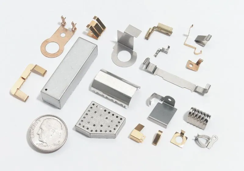
Engineers at Automech optimize strip layout design to minimize material scrap while fabricating OEM metal stamping parts
3.1.3 High-volume sheet metal production
Equipped with high-speed servo feeders and automated coil-handling systems, high-volume press lines operate continuously to produce thousands of parts per shift. Automated scrap choppers evacuate skeleton ribbons, maintaining uninterrupted press operation.
3.1.4 Sheet metal stamping for automotive OEMs
Automotive OEMs rely on sheet metal stamping to manufacture high-integrity chassis nodes, body-in-white reinforcements, powertrain brackets, and electric vehicle battery enclosures that meet rigorous crashworthiness standards.
3.2 Precision Metal Stamping
3.2.1 Dimensional tolerance requirements
Precision metal stamping achieves linear and diametrical tolerances between ± 0.005 mm and ± 0.02 mm, satisfying demanding customer specifications for electrical terminals, sensor brackets, and safety-critical latch plates.
3.2.2 Flatness and geometric accuracy
Maintaining planar datum flatness is critical for downstream automated assembly. Precision dies utilize in-die coining, reverse bending, and spring-loaded pressure pads to relieve residual stresses and hold part flatness within ± 0.05 mm across large surfaces.
3.2.3 Burr control
Punch-to-die cutting clearances are maintained below 5% to 8% of sheet thickness per side. Precision in-die shaving stations and polished cutting punches keep exit burr heights below 10% of material thickness, eliminating the need for secondary deburring.
3.2.4 Springback control
Toolmakers counteract elastic springback by incorporating over-bending cam angles, bottoming relief steps, or localized coining beads into forming cavities, ensuring bend angles consistently meet ± 0.25° drawing tolerances.
3.2.5 Surface finish requirements
Precision components often require defect-free surface topographies for aesthetic appearance or electrical contact performance. Polished die cavities, synthetic lubricants, and Physical Vapor Deposition (PVD) wear coatings prevent galling, achieving surface roughness profiles below Ra 0.4 µm.
3.2.6 Material thickness control
Because mill coil thickness variations influence punch penetration forces and forming clearances, precision stamping lines deploy contact micrometers and non-contact laser displacement gauges to monitor incoming coil strip thicknesses continuously.
3.3 Progressive Die Stamping for OEM Production
3.3.1 Progressive stamping process
Progressive die stamping advances continuous coil strip through a series of synchronized inline stations inside a single die shoe. With each press stroke, punches execute cutting, punching, coining, and forming operations while the strip advances incrementally.
3.3.2 Progressive die design
Progressive dies incorporate upper and lower die shoes, hardened ball-bearing guide pillars, spring-loaded stripper plates, pilot alignment pins, and modular punch inserts. Tool layouts are balanced to distribute cutting and forming loads evenly across the press bed.
3.3.3 Strip layout optimization
Computer-aided strip layout software determines optimal pitch distances, carrier ribbon geometry, and blank orientation. Staging operations across balanced stations prevents strip twisting and ensures consistent part geometry.
3.3.4 Material utilization
Advanced CAD nesting algorithms arrange part silhouettes to minimize the scrap skeleton left between adjacent blanks, achieving raw material utilization rates exceeding 75% to 85% to lower production costs.
3.3.5 High-volume production economics
Progressive die stamping delivers the lowest piece-part manufacturing cost at scale. By combining multiple operations into a single press stroke and automating coil feeding, the process minimizes direct labor expenses and maximizes machine output.
3.3.6 Progressive die stamping quality control
Modern progressive dies integrate in-die fiber optic sensors, acoustic tonnage monitors, and optical misfeed detectors. These systems detect misfeeds, slug pull-ups, and punch chipping instantly, halting the press automatically to prevent tool damage and defective production.
4. Automotive OEM Metal Stamping Parts
4.1 Automotive Metal Stamping Applications
4.1.1 Automotive sheet metal parts
Sheet metal stampings form the external and internal panels of modern passenger and commercial vehicles, including cowl side panels, wheelhouse arches, floor pan panels, and underbody aerodynamic guards.
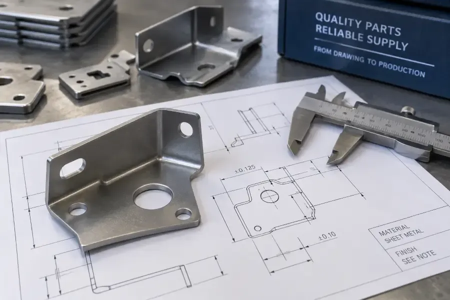
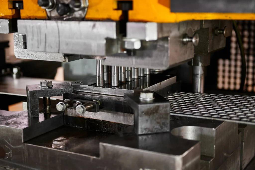
Precision stamping dies ensure high dimensional repeatability for complex OEM metal stamping parts across every batch
4.1.2 Structural automotive components
Structural stampings carry dynamic vehicle loads and absorb impact forces during collisions. These include body-in-white (BIW) B-pillar reinforcements, roof header rails, bumper crash boxes, and longitudinal chassis subframe rails.
4.1.3 Automotive brackets
Automotive brackets provide structural mounting interfaces across the powertrain compartment, suspension nodes, and passenger cabin, securing alternators, air conditioning compressors, steering gears, and fluid lines against continuous vehicle vibrations.
4.1.4 Reinforcement components
Reinforcement stampings strengthen structural joints, door intrusion beams, seatbelt anchorages, and suspension strut towers, distributing concentrated mechanical loads to safeguard passenger cabin integrity.
4.1.5 Mounting and support components
Mounting components include radiator support crossmembers, electronic control unit (ECU) shield boxes, battery tray perimeter frames, and transmission crossmembers engineered to OEM dimensional standards.
4.2 Common OEM Metal Stamping Parts
4.2.1 Automotive bracket stamping parts
Multi-flange mounting brackets featuring precision-pierced bolt holes, extruded screw bosses, and locating alignment tabs manufactured for vehicle engine bays and chassis assemblies.
4.2.2 Chassis and structural brackets
Heavy-gauge structural brackets (2.0 mm to 6.0 mm thick) engineered from high-strength steels to deliver high dynamic fatigue endurance for control arm pivots and shock absorber mountings.
4.2.3 Body and reinforcement components
Precision stamped high-strength steel reinforcement plates and corner gussets engineered to reinforce vehicle door frames, roof bows, and rocker panel sections against collision impacts.
4.2.4 Mounting plates and support brackets
Precision flat mounting plates with tight datum coplanarity, designed to secure electric drive motors, power steering racks, and hybrid inverters within compact packaging envelopes.
4.2.5 Electrical and mechanical stamped components
High-conductivity copper and aluminum EV battery busbars, battery cell terminal tabs, grounding clips, horn contacts, seat recliner gear sectors, and window regulator gears.
4.3 Automotive Stamping Assembly
4.3.1 Stamping and secondary-operation integration
Leading contract stamping facilities integrate press stamping directly with automated secondary processes-including vibratory deburring, automated hardware insertion (PEM nuts, threaded studs), and precision robotic welding.
4.3.2 Spot welding
Resistance spot welding joins overlapping stamped sheet metal components using high-current electrical pulses and pneumatic clamping force, producing clean, high-strength structural joints without adding filler wire weight.
4.3.3 MIG welding
Metal Inert Gas (MIG/GMAW) welding provides continuous, deep-penetration welded seams across heavy-gauge chassis brackets, suspension links, and subframe crossmembers subject to severe torsional loads.
4.3.4 Laser welding where applicable
Fiber laser welding delivers low heat input, narrow weld seams, and minimal thermal distortion, making it ideal for joining delicate electric vehicle battery enclosures and tailored structural blanks.
4.3.5 Fixture-controlled assembly
Custom welding and assembly fixtures utilize CNC-machined locating blocks, hardened dowel pins, and pneumatic toggle clamps to hold stamped sub-components in precise spatial alignment during joining, counteracting thermal weld distortion.
4.3.6 Finished automotive stamping assemblies
Turnkey contract manufacturers deliver complete, ready-to-install structural modules-such as dashboard cross-beams, pedal bracket assemblies, and seat frame tracks-directly to OEM vehicle assembly plants, reducing customer supply chain complexity.
5. OEM Stamping Materials and Tooling
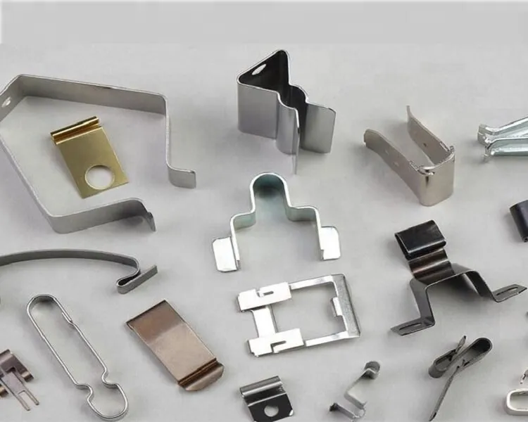
Automech applies rigorous IATF 16949 quality control standards during the serial production of OEM metal stamping parts
5.1 Materials for OEM Metal Stamping Parts
5.1.1 Carbon steel
Cold-rolled low-carbon steels (SPCC, SECC, ASTM A1008) and hot-rolled pickled and oiled steels (SPHC) provide an economical balance of tensile strength, ductility, and weldability for structural brackets, covers, and general vehicle hardware.
5.1.2 Stainless steel
Austenitic grades (SUS304, SUS316) and ferritic grades (SUS409, SUS430) deliver superior corrosion resistance, chemical stability, and heat resistance for vehicle exhaust hangers, catalytic converter heat shields, and fuel delivery clips.
5.1.3 Galvanized steel
Electro-galvanized (SECC) and hot-dip galvanized (SGCC) steel sheets incorporate a bonded zinc layer that provides sacrificial galvanic corrosion protection, preventing red rust along sheared edges on underbody vehicle components.
5.1.4 High-strength steel
High-Strength Low-Alloy (HSLA) steels provide yield strengths between 350 and 550 MPa, allowing engineers to down-gauge material thickness while preserving structural load-bearing capacity in chassis brackets and frame stiffeners.
5.1.5 AHSS for automotive applications
Advanced High-Strength Steels (AHSS)-including Dual-Phase (DP600, DP800), TRIP, and Martensitic steels-provide tensile strengths up to 1,000+ MPa. These alloys are selected for safety-critical B-pillar reinforcements and bumper crash boxes to maximize crash energy absorption.
5.1.6 Aluminum and aluminum alloys
Aluminum alloys (such as 5052-H32, 6061-T4/T6, and 5182) offer a density of ~ 2.70 g/cm³, roughly one-third that of steel. Stamping aluminum enables significant vehicle weight reduction in EV battery module enclosures, heat shields, and body closures.
5.1.7 OEM-specified sheet metals
Contract stampers process specialized metal coils certified strictly to global OEM procurement standards, including proprietary chemistries, specialized pre-lubrications, and strict mill test documentation.
5.2 OEM Metal Stamping Tooling
5.2.1 Stamping die types
Tooling architectures are tailored to part geometry and program volume, encompassing single-operation simple dies, compound blanking/piercing dies, continuous progressive dies, transfer dies, and deep drawing tools.
5.2.2 Custom die manufacturing
Toolrooms construct stamping dies using high-speed CNC machining centers, precision surface grinders, and multi-axis wire EDM machinery. Die components undergo vacuum heat treatment to achieve hardness ratings between 58 and 62 HRC.
5.2.3 Progressive stamping dies
Progressive dies integrate multi-stage cutting and forming stations into a single tool block. Built with hardened ball-bearing guide pillars and nitrogen gas springs, progressive dies deliver extended tool life and high stroke repeatability.
5.2.4 Transfer and forming dies
Transfer dies consist of separate die stations mounted along a multi-station press bed. Synchronized mechanical transfer rails move discrete workpieces between stations, accommodating large panels and deep enclosures.
5.2.5 Tool steel selection
Tool designers select premium tool steels based on wear resistance and impact toughness. Standard choices include AISI D2, DC53, and SKD11 for die blocks and punches, with tungsten carbide inserts specified for high-wear cutting edges.
5.2.6 Die component precision
Internal die components are machined to tolerances within ± 0.005 mm. Precision-ground punch holders, stripper plates, and guide bushings eliminate mechanical play, ensuring uniform cutting clearances around the punch perimeter.
5.3 Tooling Engineering and Optimization
5.3.1 Progressive die design
Engineers model the complete die assembly in 3D CAD, balancing press tonnage distribution across the tool’s center of force, calculating dynamic stripping forces, and positioning pilot locating pins to ensure smooth strip advancement.
5.3.2 CAD/CAM tooling development
Parametric 3D CAD modeling integrates directly with CAM software to generate high-speed CNC milling and wire EDM toolpaths for hardened die components, ensuring exact physical execution of simulated tooling geometry.
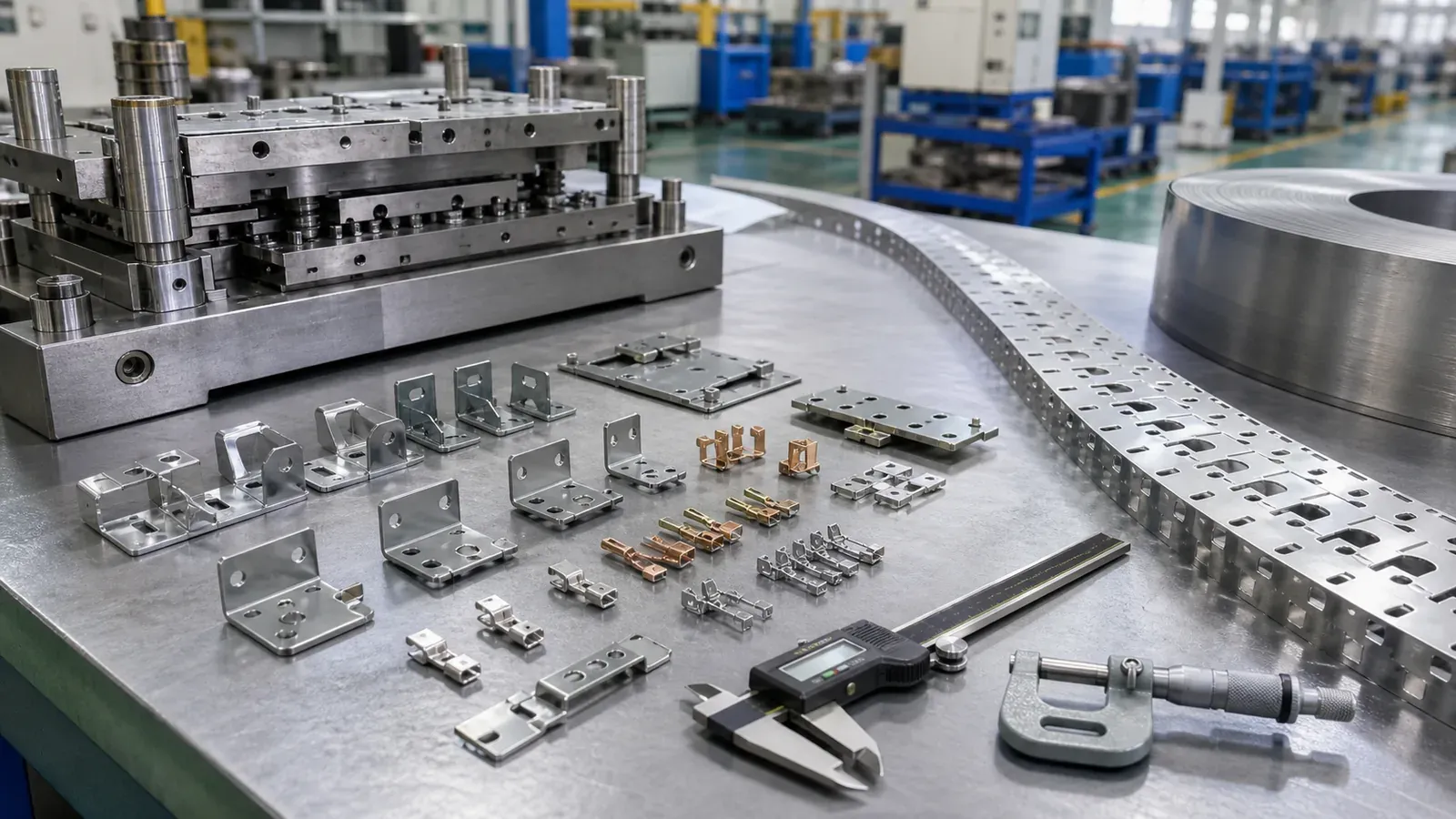
Electric vehicle platforms utilize lightweight aluminum OEM metal stamping parts to enhance overall battery range
5.3.3 Strip layout optimization
The material strip layouts are designed to maximize material utilization efficiency. Staging piercing, notching, bending, and parting operations across balanced stations prevents strip distortion and preserves carrier ribbon rigidity.
5.3.4 Material utilization optimization
Advanced blank nesting algorithms evaluate nested, angular, and interlocking arrangements to achieve raw material utilization rates exceeding 75% to 85%, directly lowering raw coil expenditures on high-volume OEM contracts.
5.3.5 Tool life optimization
Applying Physical Vapor Deposition (PVD) wear coatings-such as Titanium Aluminum Nitride (TiAlN) or Diamond-Like Carbon (DLC)-reduces friction coefficients and prevents galling, extending punch life across millions of press cycles.
5.3.6 Die maintenance and refurbishment
Structured preventive maintenance schedules govern toolroom regrinding, ultrasonic cleaning, guide pillar lubrication, and nitrogen spring inspection every 50,000 to 100,000 cycles, restoring sharp cutting edges before burr growth creates part defects.
5.3.7 Tooling change and maintenance control
All die modifications, punch sharpening records, and engineering revisions are managed through formal Engineering Change Notification (ECN) protocols. Detailed tool maintenance logs record stroke counts and component replacements to maintain full tooling traceability.
6. Secondary Operations and OEM Assembly Integration
6.1 Post-Stamping Operations
6.1.1 Deburring
Die shearing generates micro-burrs along the cut edges of stamped components. To ensure operator safety during assembly and prevent damage to mating wiring harnesses or seals, parts undergo automated deburring. Methods include vibratory bowl deburring with ceramic media, centrifugal barrel finishing, and automated abrasive belt edge-rounding.
6.1.2 Bending and forming
While progressive dies handle most geometric bends inline, complex components requiring multi-axis or reverse-angle deformation often utilize secondary bending operations. CNC press brakes and dedicated secondary hydraulic forming fixtures execute deep secondary flanges or complex wrapping contours without overcomplicating the primary stamping die.
6.1.3 Tapping and machining
Certain OEM components require high-precision internal threads or critical datum faces that cannot be achieved in the stamping press. Secondary multi-spindle tapping heads, in-die automated mechanical tappers, and CNC milling cells add clean metric or imperial threads, precision counterbores, and spot faces to stamped brackets.
6.1.4 Surface treatment
OEM stamped components operate in demanding physical environments requiring robust corrosion protection and surface hardening. Common post-stamping conversion processes include electro-zinc plating with trivalent passivations, hot-dip galvanizing, cataphoresis (E-coating), electrostatic powder coating, and chemical anodizing for aluminum alloys, designed to pass 480 to 1,000+ hours of ASTM B117 salt spray testing.
6.1.5 Part cleaning and preparation
Before finishing or assembly, stampings pass through multi-stage aqueous ultrasonic wash lines or solvent vapor degreasers. This cleaning removes residual stamping lubricants, metal fines, and particulate contaminants, ensuring pristine surface bonding for structural adhesives, welding, and electro-deposited coatings.
6.2 Welding and Assembly
6.2.1 Spot welding
Resistance spot welding joins overlapping stamped sheet metal stampings by applying localized electrical current and mechanical clamping pressure. Spot welding is ideal for automotive body-in-white (BIW) reinforcements, mounting brackets, and dual-layer heat shields, delivering rigid, high-strength structural joints without adding filler wire mass.
6.2.2 MIG welding
Metal Inert Gas (MIG/GMAW) welding provides continuous, deep-penetration weld beads across heavier structural stampings. MIG welding is widely used on chassis subframes, suspension links, and heavy-gauge engine mounting brackets, yielding high fatigue resistance under cyclic vehicle dynamic loads.
6.2.3 Laser welding where applicable
Fiber laser welding delivers concentrated energy density with minimal heat-affected zones (HAZ). It is used on electric vehicle (EV) battery enclosures, tailored blanks, and hermetically sealed covers, minimizing thermal distortion across thin sheet metal assemblies while producing clean seams.
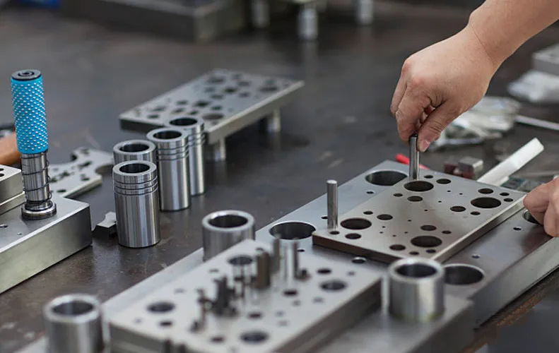
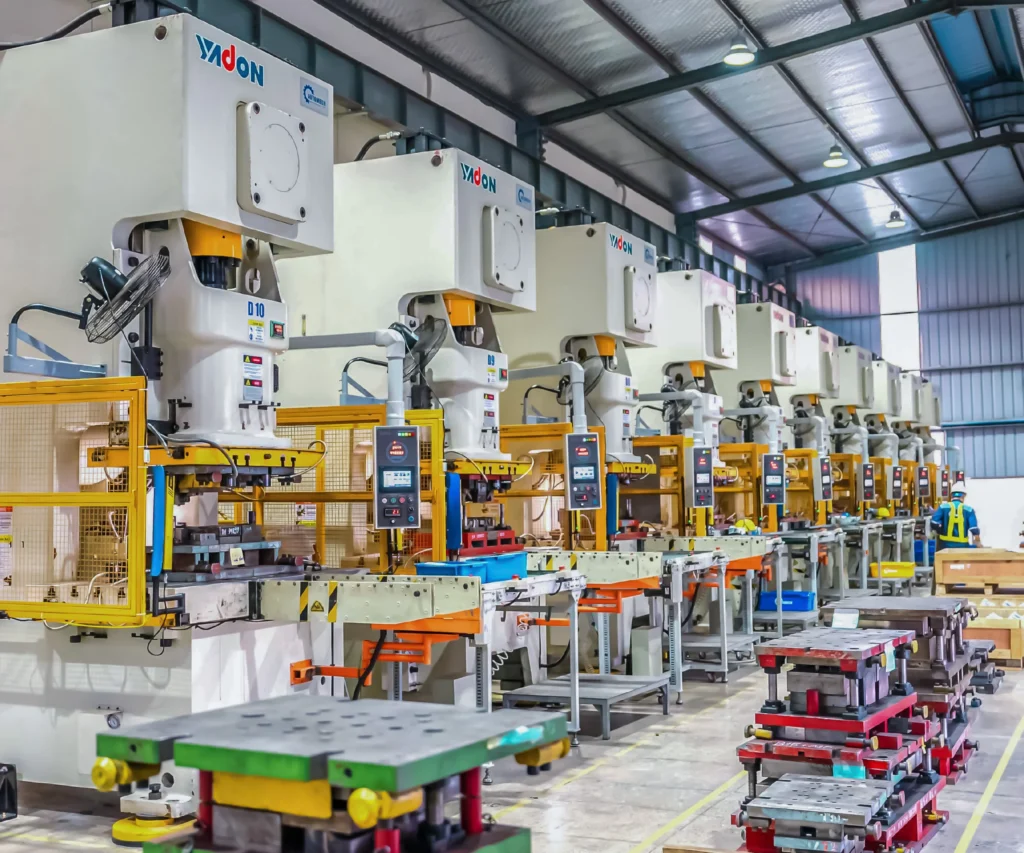
High-speed press lines enable Automech to maintain rapid cycle times when forming OEM metal stamping parts
6.2.4 Fixture-controlled assembly
To eliminate manual positioning variance, secondary joining operations utilize custom assembly and welding fixtures. Equipped with CNC-machined datum blocks, hardened locating dowel pins, and pneumatic toggle clamps, fixtures hold stamped sub-components in precise spatial alignment, preventing heat warpage and maintaining drawing GD&T callouts.
6.2.5 Multi-part stamping assembly
Contract manufacturers combine individual stamped stampings with hardware fasteners, threaded studs, self-clinching PEM nuts, rubber vibration dampers, and plastic bushings. Consolidating multiple parts into a completed sub-assembly simplifies customer procurement and lowers downstream production costs.
6.3 Prototype to Mass Production
6.3.1 Prototype stamping
The prototyping phase validates component geometry, mechanical fitment, and assembly clearance. Prototype parts are produced using laser cutting, CNC punch presses, and modular soft tooling, allowing engineering teams to test functional physical parts before investing in hardened production dies.
6.3.2 Low-volume production
Low-volume manufacturing (typically 500 to 5,000 units) accommodates pilot vehicle builds, bridge production runs, and specialized equipment manufacturing. Suppliers utilize single-operation modular dies or hybrid tooling setups, balancing initial tooling investment against unit delivery schedules.
6.3.3 Pilot production
Pilot production runs evaluate production stamping dies under commercial operating speeds. Stamping a trial lot of several thousand parts validates automated coil feeding stability, in-die sensor interlocks, scrap evacuation, and cycle-time repeatability prior to high-volume manufacturing approval.
6.3.4 Process validation
During process validation, quality assurance teams verify that the press, tooling, and secondary assembly cells can operate continuously within established control limits. Statistical evaluations verify process capability indices (Cpk1.67), proving the manufacturing process is stable and repeatable.
6.3.5 High-volume mass production
Mass production represents the steady-state manufacturing phase where automated coil lines, progressive dies, and robotic welding cells produce hundreds of thousands to millions of components annually under continuous Statistical Process Control (SPC).
6.3.6 Production capacity planning
Effective capacity planning aligns press tonnage, coil raw material inventories, machine maintenance intervals, and labor shifts with customer release schedules. Enterprise Resource Planning (ERP) systems coordinate raw coil deliveries and press changeovers, maximizing Overall Equipment Effectiveness (OEE).
7. OEM Quality Requirements and Manufacturing Compliance
7.1 OEM Metal Stamping Quality Control
7.1.1 Dimensional inspection
Dimensional quality control begins at the press line. Operators and quality inspectors utilize calibrated micrometers, depth gauges, digital height stands, and optical profile projectors to verify linear dimensions, hole diameters, and bend angles against engineering drawings.
7.1.2 CMM inspection
Coordinate Measuring Machines (CMM) located in climate-controlled quality laboratories (~ 20°C) inspect complex 3D form profiles, hole true positions, and geometric dimensioning and tolerancing (GD&T) datums. CMM inspection validates physical production parts directly against customer 3D CAD nominals.
7.1.3 Vision inspection
Automated in-line vision systems installed along press exit conveyors inspect 100% of finished parts at production line speeds. High-resolution optical cameras detect missing holes, slot deformation, incorrect forming features, and severe exit burrs before parts are packed.
7.1.4 Gauge inspection
Custom attribute checking fixtures, drop indicator fixtures, and go/no-go plug gauges provide fast verification on the shop floor. These hard gauges simulate mating assembly interfaces to confirm immediate fitment before packaging.
7.1.5 First Article Inspection
Before authorizing mass production runs, quality engineers conduct a complete First Article Inspection (FAI) on initial stamped parts off the tool. FAI reports verify that die shut-height calibration, strip pitch, and punch offsets yield fully conforming components.
7.1.6 In-process SPC
Statistical Process Control (SPC) protocols track critical part dimensions at regular production intervals. Press operators extract sample parts at defined intervals, recording measurements on X-bar and R control charts to monitor process capability and prevent dimensional drift.
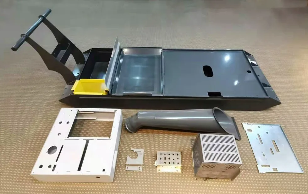
Global supply chains source durable OEM metal stamping parts from Vietnam to optimize overall manufacturing expenditur
7.1.7 Final inspection and release
Completed production lots undergo final outgoing inspection, verifying surface finish, plating thickness, lot counts, and protective packaging integrity. The quality department issues a formal Certificate of Conformance (CoC) and inspection report prior to shipping.
7.2 Automotive Quality Management Systems
7.2.1 ISO 9001 requirements
ISO 9001 establishes the foundational Quality Management System (QMS), standardizing operating procedures, raw material verification, equipment calibration, and structured continuous improvement (PDCA) routines across all manufacturing operations.
7.2.2 IATF 16949 requirements
IATF 16949 enforces automotive-specific quality management requirements focused on defect prevention, supply chain variation reduction, automated error-proofing (Poka-Yoke), and complete raw material-to-part traceability.
7.2.3 Automotive supplier quality management
Automotive OEMs mandate that contract stamping suppliers implement formal supplier quality management procedures, requiring systematic audits of sub-tier material suppliers, steel coil service centers, and external electro-plating vendors.
7.2.4 Process control and continuous improvement
Process control requires ongoing monitoring of production parameters, scrap rates, and tooling wear trends. Continuous improvement initiatives (Kaizen) analyze operational metrics to eliminate waste, optimize cycle times, and improve component quality.
7.3 OEM Quality Documentation
7.3.1 APQP
Advanced Product Quality Planning (APQP) provides a structured project management roadmap from initial tool design through full mass-production launch. Cross-functional teams evaluate technical feasibility, track tooling milestones, and mitigate manufacturing risks before starting die fabrication.
7.3.2 PPAP
The Production Part Approval Process (PPAP) demonstrates that the stamping line can produce parts meeting all engineering drawing requirements at full production press speeds. Tier suppliers typically submit Level 3 PPAP packages, including sample parts, dimensional results, material certifications, and process capability studies.
7.3.3 FMEA
Failure Mode and Effects Analysis (Design FMEA and Process FMEA) proactively identifies potential failure modes in tooling design or press operations. Engineering teams implement preventive countermeasures-such as optical misfeed sensors, guided stripper pads, and hardened punch inserts-to eliminate high-risk failure modes.
7.3.4 Control Plan
A comprehensive Control Plan defines specific inspection checkpoints, measuring instruments, sample frequencies, and reaction protocols across every stage of production-including incoming coil receiving, blanking, forming, deburring, plating, and packaging.
7.3.5 MSA
Measurement Systems Analysis (MSA), including Gage Repeatability and Reproducibility (Gage R&R) studies, verifies that inspection tools and operator techniques introduce minimal measurement error. Maintaining Gage R&R values below 10% ensures dependable dimensional verification data.
7.3.6 SPC
Statistical Process Control charts track process stability over time. Tracking critical dimensions ensures process capability indices remain above customer requirements (Cpk1.67), preventing non-conforming parts from being produced.
7.3.7 Traceability and quality records
Digital quality systems maintain complete lot traceability for every production batch. Laser-etched 2D DataMatrix barcodes or stamped batch numbers link finished stampings directly to raw material master coil certifications, tool maintenance history, press machine IDs, and inspection logs for 10 to 15 years.
8. OEM Metal Stamping Cost and Production Economics
8.1 OEM Metal Stamping Pricing Factors
8.1.1 Material cost
Raw material selection establishes the baseline cost of any stamped part. Advanced High-Strength Steels (AHSS), austenitic stainless steel (SUS304), and structural aluminum alloys command market price premiums over commercial-grade cold-rolled carbon steel (SPCC).
8.1.2 Part geometry and complexity
Component geometry directly dictates the number of active forming stations, punch configurations, and press operational speeds. Complex 3D parts requiring deep draw recesses, compound flanges, and dense hole matrices require larger progressive dies, increasing non-recurring tooling investment.
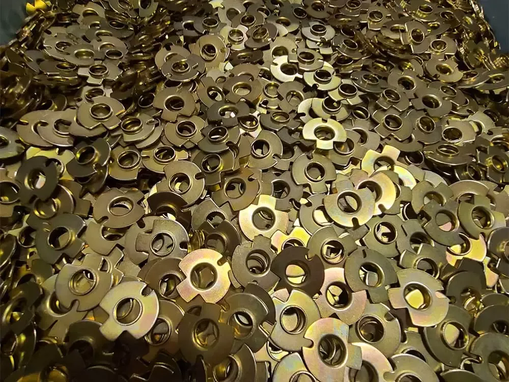
Automech integrates smart in-die inspection sensors to guarantee zero-defect quality across all OEM metal stamping parts
8.1.3 Material thickness
Sheet thickness dictates required press tonnage and raw metal weight per thousand parts. Thicker structural plates (3.0 mm to 6.0 mm) demand heavier-tonnage press lines and premium die steels, which increases hourly press machine rates.
8.1.4 Production volume
Total order volume governs how effectively non-recurring engineering (NRE) setup and tooling expenses amortize. High-volume programs amortize fixed tooling costs across hundreds of thousands of parts, delivering low per-unit manufacturing costs compared to prototype or low-volume batches.
8.1.5 Dimensional tolerance
Demanding dimensional tolerances (down to ± 0.01 mm) require precision carbide die inserts, automated in-die sensor monitoring, and complete CMM measurement reporting, which are reflected in final manufacturing estimates.
8.1.6 Secondary operations
Post-stamping processing steps-such as barrel deburring, robotic welding, hardware insertion, and protective surface plating-add operational stages to the workflow, influencing final finished unit pricing.
8.1.7 Inspection and quality requirements
Components requiring 100% automated optical inspection, continuous in-line laser thickness tracking, comprehensive SPC data logging, and full Level 3 PPAP packages involve dedicated quality equipment and engineering oversight.
8.2 Tooling Cost and Amortization
8.2.1 Initial stamping die investment
Stamping die fabrication represents a significant upfront capital expenditure. Dies require precision multi-axis CNC milling, wire EDM machining, vacuum heat treatment, and manual assembly of premium tool steel blocks and nitrogen gas springs.
8.2.2 Progressive die tooling cost
Progressive dies incorporate multiple sequential stations into a single continuous tool block, requiring higher initial toolmaking capital than simple single-operation dies. However, they eliminate intermediate handling labor and deliver the lowest unit piece price at volume.
8.2.3 Tooling life and maintenance cost
Dies constructed from high-grade tool steels (DC53, SKD11) or tungsten carbide inserts withstand millions of press strokes. While premium die materials increase initial tooling budgets, they eliminate premature wear and frequent maintenance halts.
8.2.4 Tooling amortization per part
For OEM programs, tooling investments can be paid upfront as a non-recurring engineering (NRE) charge or amortized into the piece-part unit price across agreed initial delivery volumes (e.g., across the first 50,000 or 100,000 units).
8.2.5 Tooling ownership and maintenance responsibility
Standard OEM contract stamping agreements specify that the customer owns the tooling, while the supplier assumes operational responsibility for routine preventive maintenance, punch sharpening, and secure storage throughout the active lifecycle of the vehicle or product platform.
8.3 Production Volume and Cost Optimization
8.3.1 Low-volume vs high-volume stamping
Low-volume stamping prioritizes lower upfront tooling expense through modular or single-operation dies, accepting higher per-piece labor costs. High-volume stamping invests in automated progressive or transfer dies to achieve the lowest piece-part rate.
8.3.2 Material utilization optimization
Optimizing strip layouts through automated blank nesting software minimizes scrap skeleton generation between adjacent blanks. Improving coil width utilization directly reduces raw material expenditure per finished component.
8.3.3 Cycle-time optimization
Automated high-speed progressive presses running at 100 to 300+ strokes per minute achieve maximum production efficiency, significantly lowering machine hourly overhead costs per component.
8.3.4 Progressive stamping cost advantages
Progressive die stamping delivers substantial cost advantages for high-volume orders by combining piercing, forming, and blanking into a single stroke, operating continuously with minimal direct labor intervention.
8.3.5 Part consolidation through stamping and assembly
Engineers frequently consolidate multi-piece fabricated assemblies into a single stamped and formed component, eliminating fasteners, reducing assembly labor, and improving overall structural integrity.
9. How to Choose an OEM Metal Stamping Supplier
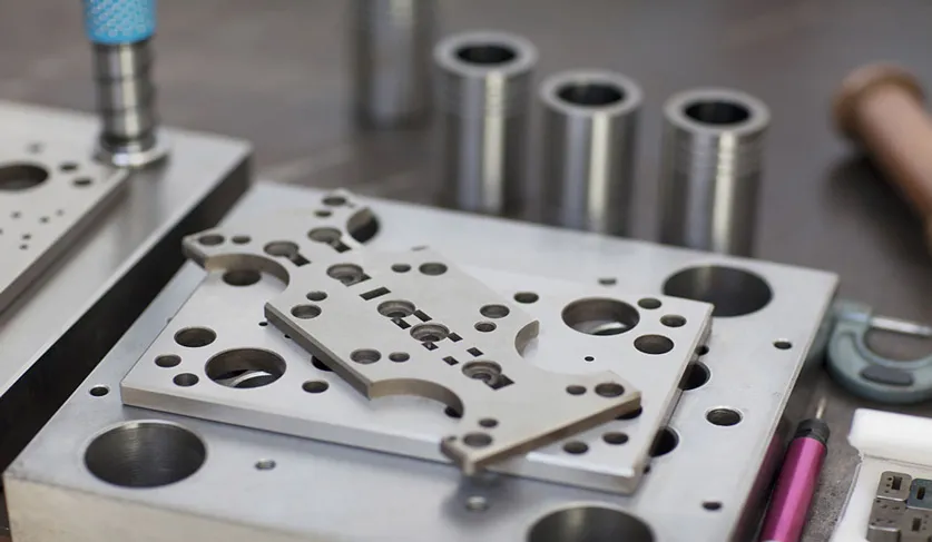
Implementing progressive die tooling significantly reduces unit production costs for OEM metal stamping parts
9.1 OEM Supplier Evaluation Criteria
9.1.1 Manufacturing capability
Verify that the supplier operates a comprehensive press fleet covering mechanical, hydraulic, and servo presses with capacities ranging from 100 tons to over 1,300 tons, capable of handling thin precision foils up to heavy structural plate.
9.1.2 Engineering and DFM capability
Choose a manufacturer that offers upfront Design for Manufacturability (DFM) reviews. Experienced engineers identify opportunities to optimize bend radii, increase hole-to-edge clearances, and improve strip layouts, reducing tooling complexity and piece-part costs before tool steel is cut.
9.1.3 Tooling and die-making capability
Prioritize suppliers that maintain in-house toolrooms equipped with high-precision wire EDM, CNC milling centers, and optical profile grinders. In-house toolmaking ensures direct control over die precision, fast prototype turnaround, and immediate preventive die maintenance.
9.1.4 Production capacity
Assess the supplier’s press capacity, factory floor space, and automated assembly systems to confirm they can scale from initial pilot runs to high-volume production without causing manufacturing bottlenecks.
9.1.5 Quality management systems
Confirm that the supplier holds active ISO 9001 certification for baseline quality management and IATF 16949 certification for automotive component manufacturing, demonstrating compliance with international process control standards.
9.1.6 Inspection and traceability systems
Ensure the supplier operates a climate-controlled quality laboratory (~ 20°C) equipped with Coordinate Measuring Machines (CMM), optical vision comparators, and surface profilometers, backed by digital lot traceability systems.
9.1.7 Export and international logistics capability
Select a partner experienced in international export logistics, customs compliance, and protective export packaging. Reliable suppliers utilize VCI anti-corrosion materials, ocean-freight palletizing, and clear batch labeling to ensure parts arrive without handling damage or oxidation.
9.2 OEM Supplier Qualification Process
9.2.1 Technical capability assessment
The qualification process begins with reviewing the supplier’s equipment lists, press specifications, toolroom machinery, and engineering software platforms to verify alignment with project requirements.
9.2.2 Quality system evaluation
Quality auditors evaluate the supplier’s documented procedures, calibration logs, internal audit records, and non-conformance management systems against ISO 9001 or IATF 16949 requirements.
9.2.3 Production facility audit
OEM procurement teams conduct on-site factory audits (such as VDA 6.3 process audits) to evaluate shop floor cleanliness, preventive maintenance execution, material flow, and error-proofing (Poka-Yoke) systems.
9.2.4 Sample and prototype validation
The supplier produces physical prototype samples or trial stampings. Technicians inspect these parts for dimensional accuracy, material properties, and edge quality to confirm toolmaking capabilities.
9.2.5 PPAP and supplier approval
The supplier submits a complete PPAP package (typically Level 3). Upon customer engineering sign-off on dimensional data, material certifications, and capability studies, the supplier is granted formal approved vendor status.
9.2.6 Production readiness assessment
Before authorizing full-rate production, a formal run-at-rate evaluation confirms that the supplier’s press line, material handling, and quality inspection cells can meet target cycle speeds and output volumes under actual operating conditions.
9.3 OEM Metal Stamping Supplier Checklist
9.3.1 Drawing and CAD capability
Proficiency in importing, interpreting, and manipulating 3D CAD data (STEP, IGES) and 2D engineering drawings with complex GD&T callouts.
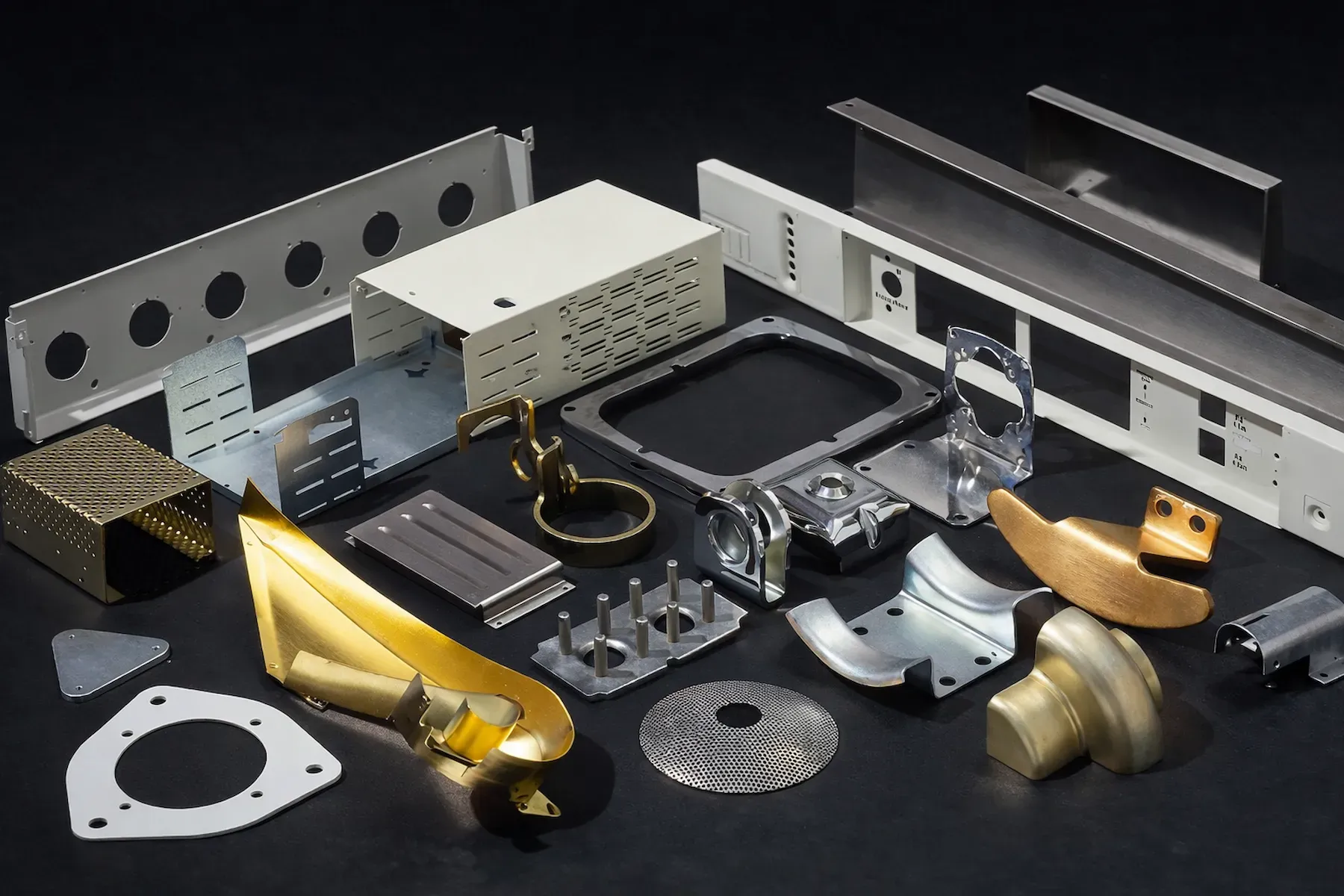
With high-tonnage automated presses, Automech efficiently fabricates custom OEM metal stamping parts for global clients
9.3.2 Material sourcing and certification
Established relationships with accredited steel and aluminum mills, providing full Mill Test Reports (MTR) verifying chemical and mechanical compliance.
9.3.3 Tooling development capability
In-house tool and die design, CNC milling, wire EDM machining, and tool maintenance infrastructure capable of building progressive, transfer, and compound dies.
9.3.4 Quality inspection capability
Climate-controlled quality lab equipped with multi-axis CMM, optical profile projectors, surface roughness gauges, and hard attribute check fixtures.
9.3.5 Production scalability
Versatile press capacity and multi-shift operating models capable of scaling from initial pre-series batches to continuous high-volume mass production.
9.3.6 Supply continuity and risk management
Structured preventive maintenance programs, redundant press capacity, robust supply chain management, and emergency response plans ensuring uninterrupted delivery.
9.3.7 US/EU export experience
Proven history of manufacturing and exporting components to North American and European OEM supply chains, adhering to international logistics, tariff, and commercial protocols.
10. OEM Metal Stamping RFQ and Sourcing Process
10.1 What to Include in an OEM Stamping RFQ
10.1.1 Technical drawings
Provide fully dimensioned 2D engineering drawings (PDF format) detailing all linear and angular dimensions, geometric dimensioning and tolerancing (GD&T) callouts, thread callouts, and required edge conditions.
10.1.2 3D CAD files
Submit clean 3D CAD models (STEP or IGES format) matching the 2D drawings to enable tooling engineers to analyze 3D geometry and perform metal forming simulations.
10.1.3 Material specifications
Explicitly define raw material specifications (such as ASTM, EN, or JIS alloy designations), temper/hardness conditions, and sheet gauge thickness along with allowable mill thickness tolerances.
10.1.4 Annual and batch production volumes
Disclose projected annual usage (EAU) alongside estimated release batch sizes and prototype requirements, allowing toolmakers to propose the most cost-efficient tooling architecture.
10.1.5 Dimensional tolerances
Distinguish critical functional mating dimensions from non-critical exterior features to avoid unnecessary precision tooling costs.
10.1.6 Surface-finish requirements
State all required secondary finishing processes upfront-including deburring, zinc plating, E-coating, powder coating, or anodizing-along with required salt-spray test durations.
10.1.7 Quality and certification requirements
Outline required quality compliance deliverables upfront, including whether the project mandates Level 3 PPAP submissions, specific Gage R&R studies, or specialized testing fixtures.
10.2 OEM Metal Stamping RFQ Process
10.2.1 Submit drawings and specifications
The sourcing process initiates when the buyer submits technical drawings, 3D CAD models, material specifications, and production forecasts to the supplier’s engineering portal.
10.2.2 DFM review
The supplier’s engineering team reviews the CAD models and drawings, evaluating bend radii, hole clearances, and blank profiles to identify cost-reduction and manufacturability improvements.
10.2.3 Tooling feasibility assessment
Tool designers evaluate strip progression options, punch clearances, draw depths, and press tonnage requirements to determine the optimal die configuration (progressive, transfer, or compound).
10.2.4 Manufacturing process proposal
The supplier develops a comprehensive manufacturing roadmap outlining the proposed strip progression, press machine assignment, secondary deburring, plating, and quality control gates.
10.2.5 Tooling and part cost quotation
The supplier issues a formal quotation providing transparent itemized pricing for non-recurring tooling engineering (NRE), volume-tiered piece-part costs, sample lead times, and mass production delivery schedules.
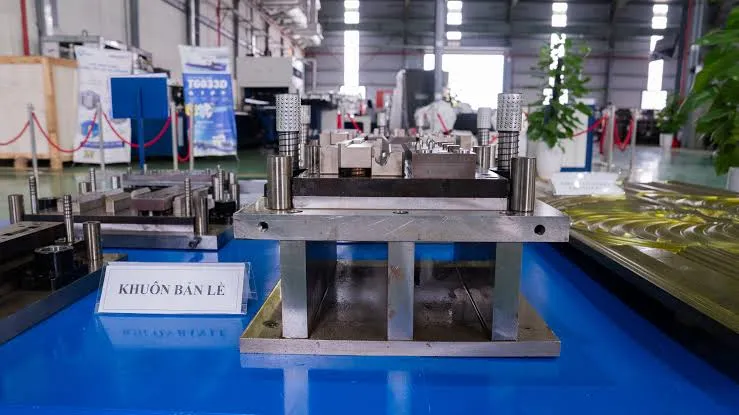
Automotive manufacturers rely on tight-tolerance OEM metal stamping parts to assemble structural body frames
10.2.6 Prototype quotation
If physical prototype validation is required, the quotation details soft-tooling or laser-cut prototype costs and delivery timelines.
10.2.7 Production validation
Following tool build, the supplier runs trial stampings, measures parts via CMM, and prepares initial sample parts alongside First Article Inspection reports for customer engineering sign-off.
10.2.8 Mass-production quotation and supply agreement
Upon final sample approval and signed PPAP approval, the commercial supply agreement is executed, establishing rolling delivery schedules, inventory buffer requirements, and payment terms.
10.3 OEM Sourcing and Supply Chain Considerations
10.3.1 Automotive stamping OEM sourcing
Automotive sourcing requires long-term commitment. Suppliers must demonstrate financial stability, production capacity, and strict adherence to IATF 16949 standards over multi-year vehicle production platforms.
10.3.2 Supply chain diversification
Relying entirely on a single manufacturing origin exposes OEMs to regional disruptions, geopolitical tensions, and logistics bottlenecks. Sourcing stamped sheet metal parts from diversified regions builds supply chain resilience.
10.3.3 China+1 sourcing strategy
International procurement teams actively implement “China+1” sourcing strategies, establishing secondary manufacturing partnerships in Southeast Asia to reduce tariff exposure and operational risk while maintaining high quality.
10.3.4 Automotive stamping partner selection
Selecting an automotive stamping partner requires balancing technical tooling capability, quality management maturity, and open commercial communication.
10.3.5 Long-term OEM supplier development
Successful OEM relationships involve collaborative continuous improvement programs, joint cost-down initiatives, and shared capacity planning to support future product platforms.
11. Vietnam as an OEM Metal Stamping Manufacturing Destination
11.1 Why Source OEM Metal Stamping Parts from Vietnam?
11.1.1 Manufacturing cost competitiveness
Vietnam provides an advantageous cost structure for labor-intensive and high-precision metal stamping operations. Favorable operational overheads and competitive labor costs allow contract manufacturers to deliver high-quality stamped components at competitive global pricing.
11.1.2 Automotive supporting industry ecosystem
Vietnam’s industrial manufacturing sector has developed a robust supporting ecosystem for metalworking, precision toolmaking, and metal finishing. Industrial clusters house specialized facilities for vacuum heat treatment, electro-plating, E-coating, and raw coil slitting.
11.1.3 Engineering and manufacturing capabilities
Vietnamese precision stamping facilities operate modern imported machinery-including multi-axis CNC machining centers, precision wire EDM machinery, and high-tonnage mechanical and hydraulic press lines-capable of manufacturing complex progressive dies and precision parts.
11.1.4 Export manufacturing infrastructure
Vietnam benefits from an extensive network of bilateral and multilateral Free Trade Agreements (such as the EVFTA and CPTPP) that reduce trade barriers. Deep-water container ports (Lach Huyen, Cai Mep) provide direct ocean shipping routes to North America and Western Europe.
11.1.5 Supply chain diversification opportunities
Vietnam represents an established, politically stable industrial destination for global OEMs seeking supply chain resilience and diversification in Southeast Asia.
11.2 Vietnam vs China for OEM Metal Stamping
11.2.1 Manufacturing cost comparison
Vietnam maintains a clear operational cost advantage over China’s coastal manufacturing hubs, where industrial land prices and labor costs have risen steadily, delivering savings on both tooling builds and recurring piece-part production.
11.2.2 Tooling and engineering capability
While China possesses a massive tooling infrastructure, leading Vietnamese contract toolrooms have closed the technical gap, utilizing identical CAD/CAM engineering platforms, imported CNC/wire EDM machinery, and premium Japanese/European tool steels.
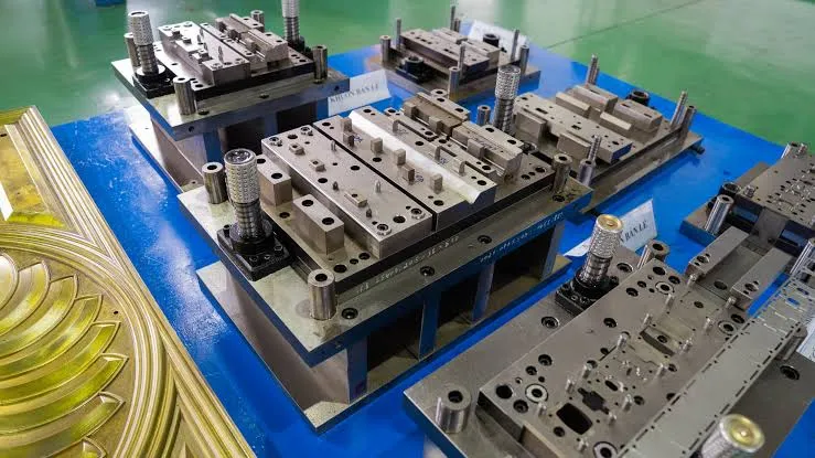
Partnering with Automech gives tier-one suppliers a competitive edge in procuring durable OEM metal stamping parts
11.2.3 Quality and supplier qualification
Vietnamese contract stamping suppliers operate under identical international quality frameworks (ISO 9001, IATF 16949) as tier-level suppliers globally, providing full Level 3 PPAP documentation and digital batch traceability.
11.2.4 Production scalability
With major industrial parks expanding and capital investment flowing into advanced press lines, Vietnamese manufacturers can scale from pilot development to high-volume OEM mass production.
11.2.5 Export and logistics considerations
Direct maritime routes link Vietnamese deep-water seaports to the United States West Coast (approximately 18 to 22 days transit) and major European ports, offering reliable logistics lead times.
11.2.6 China+1 sourcing strategy
Vietnam serves as the primary hub for corporate China+1 supply chain diversification, allowing international OEMs to establish redundant production lines without sacrificing manufacturing quality.
11.2.7 When Vietnam is the better sourcing option
Vietnam is the preferred sourcing choice for OEM programs seeking to mitigate geopolitical trade risks, reduce tariff exposure, and achieve balanced manufacturing costs without compromising engineering standards.
11.3 Vietnam OEM Stamping Supplier Capabilities
11.3.1 Automotive stamping manufacturing
Manufacturing structural body parts, chassis brackets, and electric vehicle battery components adhering to international automotive engineering standards.
11.3.2 Precision metal stamping
Producing tight-tolerance components held within ± 0.01 mm for vehicle electronics, sensor mountings, and consumer appliances.
11.3.3 Progressive die stamping
Continuous high-speed progressive die stamping operating at 100 to 500+ strokes per minute for high-volume OEM contracts.
11.3.4 Automotive sheet metal parts
Forming functional covers, splash guards, and structural panels from diverse steel and aluminum alloys.
11.3.5 Automotive bracket manufacturing
Manufacturing heavy-gauge structural and mounting brackets with integrated pierced holes, coined edges, and formed flanges.
11.3.6 Tool and die manufacturing
In-house CAD/CAM design, precision wire EDM cutting, CNC machining, and maintenance of progressive and transfer stamping dies.
11.3.7 Welding and assembly
Turnkey assembly integration combining press stamping with robotic resistance spot welding, automated MIG/TIG welding, and mechanical hardware fastening.
12. Automech OEM Metal Stamping Parts Manufacturing
12.1 OEM Metal Stamping Manufacturing Capabilities
12.1.1 OEM metal stamping parts manufacturing
Established in 2020, Automech (Automech Mechanical Equipment and Solutions Joint Stock Company) provides comprehensive contract metal stamping services for global OEMs. The company manufactures custom structural, chassis, and body components conforming to international engineering standards.
12.1.2 Sheet metal stamping
Automech operates modern mechanical, hydraulic, and servo press machinery to process flat sheets and continuous coils into durable brackets, protective covers, and structural panels.
12.1.3 Precision metal stamping
Automech delivers precision metal stamping solutions with tight dimensional tolerance control and burr-free edge quality, supporting critical electronics, appliances, and automotive sub-assemblies.
12.1.4 Progressive die stamping
Equipped with automated decoilers, straighteners, and high-speed servo feeders, Automech designs and operates progressive die systems that execute continuous piercing, bending, and forming in single tool sets for high-volume orders.
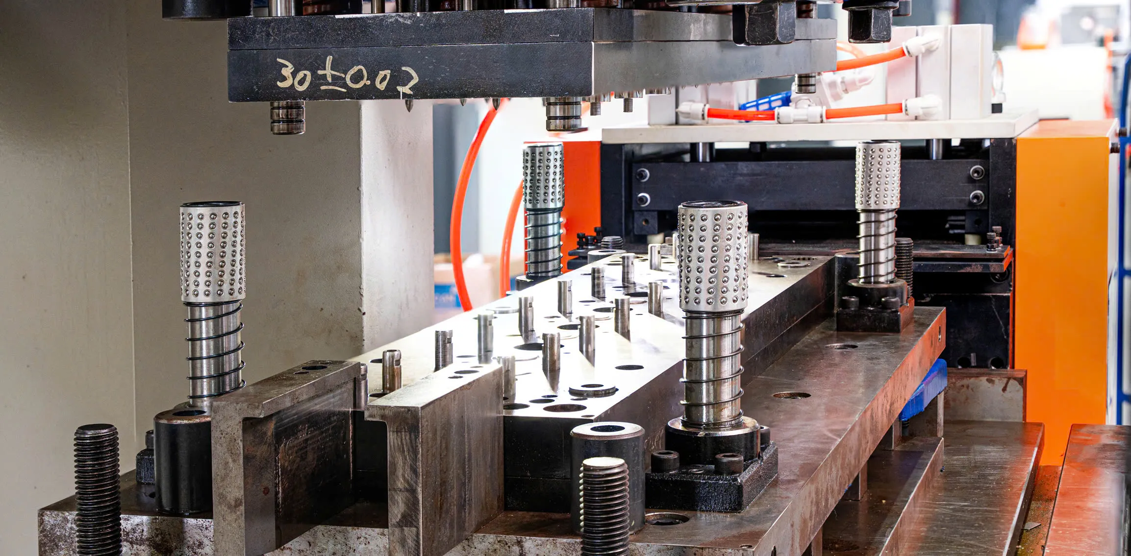
Continuous quality audits ensure that all OEM metal stamping parts conform strictly to automotive safety regulations
12.1.5 Automotive stamping
Automech specializes in automotive structural sheet metal components, electric bus frame structures, interior panels, and body-in-white (BIW) reinforcements.
12.1.6 Automotive bracket manufacturing
Automech manufactures motor mounts, suspension brackets, sensor holders, and chassis gussets with precise hole patterns and formed flange angles across mass batches.
12.2 Engineering and Tooling Support
12.2.1 Technical drawing and CAD review
Automech’s technical engineering team reviews customer 2D drawings and 3D CAD files to establish precise manufacturing parameters and GD&T requirements.
12.2.2 DFM engineering support
Automech conducts thorough upfront Design for Manufacturability (DFM) reviews to identify opportunities for material optimization, bend radius standardization, and die complexity reduction before tool steel is cut.
12.2.3 Custom die manufacturing
Factory 1 in Bac Ninh (10,500 m²) features dedicated tooling areas, CNC machining centers, wire EDM machines, and tryout presses for die manufacturing.
12.2.4 Progressive die development
Automech designs and fabricates multi-station progressive dies in-house, balancing cutting and forming forces to ensure extended tool life and high dimensional repeatability.
12.2.5 Tooling feasibility and cost optimization
Using metal forming simulation, Automech analyzes strip thinning limits, springback behavior, and press tonnage distribution to optimize die construction and lower piece-part costs.
12.2.6 Prototype-to-production engineering
Automech supports every stage of product development, from soft-tool prototype stamping and pilot validation in Factory 1 to automated high-volume production in Factory 2 in Bac Ninh (10,000 m², inaugurated June 2026, targeting an 80% automation rate).
12.3 Welding, Assembly and Production Integration
12.3.1 Stamping and welding integration
Automech integrates robotic welding cells, spot welding stations, laser welding, and ultrasonic welding systems directly with press stamping operations.
12.3.2 Fixture-controlled assembly
To ensure accurate alignment, Automech designs and builds precision welding jigs and inspection fixtures (Jigs) in-house, preventing thermal distortion during automated joining.
12.3.3 Automotive stamping assembly
Production assets include automated 800-ton to 1,300-ton tandem stamping press lines with ABB industrial robots, alongside robotic welding cells equipped with KUKA articulated robots and Fronius welding systems.
12.3.4 Prototype and pilot production
Automech operates dedicated pilot production cells to validate tooling performance, cycle speeds, and assembly fit-up before full-scale commercial release.
12.3.5 Low-volume and mass production
Flexible press lines accommodate low-volume specialty runs as well as high-volume OEM mass production programs delivering millions of parts annually.
12.4 Quality and OEM Supplier Support
12.4.1 Quality inspection systems
Automech operates climate-controlled quality laboratories (~ 20°C) equipped with Coordinate Measuring Machines (CMM) and optical profile projectors.
12.4.2 CMM, vision, and gauge inspection
Quality technicians execute multi-axis CMM dimensional validation, custom checking fixture verification, and automated optical inspections to confirm GD&T compliance.
12.4.3 PPAP, APQP, FMEA, Control Plan, MSA and SPC
Automech supports OEM quality deliverables by preparing complete PPAP packages up to Level 3, incorporating APQP project tracking, Process FMEA, Control Plans, Gage R&R studies, and ongoing SPC control charts.
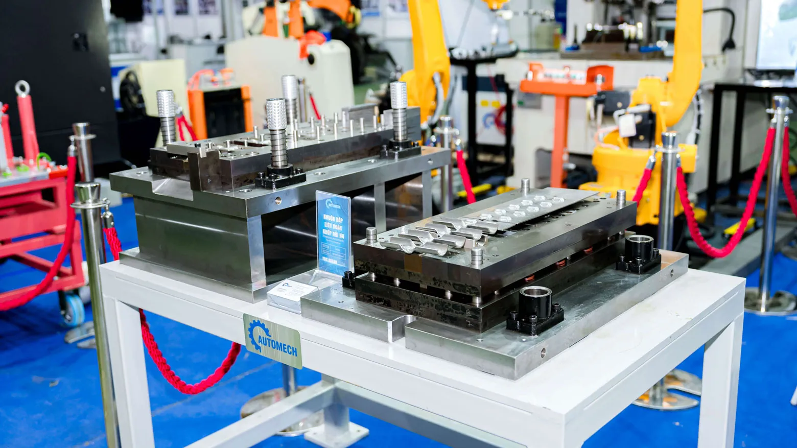
Automech specializes in providing full-service contract manufacturing for complex OEM metal stamping parts
12.4.4 Traceability and supplier quality systems
Digital quality management systems maintain complete batch traceability linking finished components to raw material master coil test certificates, machine parameters, and operator shifts.
12.4.5 ISO 9001 / IATF 16949 compliance where applicable
Automech operates under certified quality management systems aligned with ISO 9001 and automotive IATF 16949 requirements, ensuring continuous process standardization and defect prevention.
12.5 US and European OEM Sourcing
12.5.1 OEM and Tier 1/Tier 2 supplier support
Automech has demonstrated proven execution capabilities across major industrial manufacturing programs for leading enterprises, including VinFast, VinES, Hoa Phat, Kim Long Motors, and Seojin.
12.5.2 Automotive component export capability
Automech prepares export orders with protective Vapor Corrosion Inhibitor (VCI) packaging, custom palletizing, clear labeling, and comprehensive customs export documentation.
12.5.3 US OEM sourcing support
Automech’s engineering team complies with North American automotive standards, providing transparent technical communication and dependable logistics support for US buyers.
12.5.4 European OEM sourcing support
Automech adheres to European technical norms and environmental regulations, utilizing direct ocean shipping corridors from northern Vietnam’s deep-water ports.
12.5.5 Supply chain diversification from China
Automech offers international buyers a dependable, high-capability manufacturing alternative in Vietnam to support long-term China+1 sourcing strategies.
12.5.6 Long-term OEM manufacturing partnerships
Backed by nationwide technical service hubs in Hanoi, Bac Ninh, Hai Phong, Da Nang, Hue, and Ho Chi Minh City, Automech builds lasting manufacturing partnerships based on engineering collaboration and supply continuity.
12.6 Request an OEM Metal Stamping RFQ
12.6.1 Upload technical drawings
Submit fully dimensioned 2D engineering drawings (PDF) detailing critical tolerances, hole callouts, and GD&T requirements.
12.6.2 Upload CAD files
Share 3D CAD models (STEP, IGES) for geometric analysis, finite element forming simulation, and strip progression modeling.
12.6.3 Request DFM review
Obtain a comprehensive Design for Manufacturability review identifying opportunities to standardize bend radii, optimize hole clearances, and reduce tooling costs.
12.6.4 Request tooling feasibility review
Receive a detailed tooling feasibility assessment evaluating metal stretch limits, springback behavior, and press tonnage distribution prior to capital commitment.
12.6.5 Request OEM stamping cost analysis
Request a detailed cost analysis evaluating coil nesting layouts, material utilization rates, and progressive die economics.
12.6.6 Request supplier qualification information
Obtain Automech’s supplier qualification package, including ISO 9001 and IATF certificates, equipment lists, and past project references.
12.6.7 Contact the engineering team
Connect directly with Automech’s mechanical engineers and toolmakers to discuss custom progressive die configurations and production scheduling.
12.6.8 Get an OEM metal stamping quotation
Contact Automech today to receive a competitive, volume-tiered quotation for prototype development, pre-series runs, or mass-production OEM metal stamping projects in Vietnam.
13. OEM Metal Stamping Parts FAQ
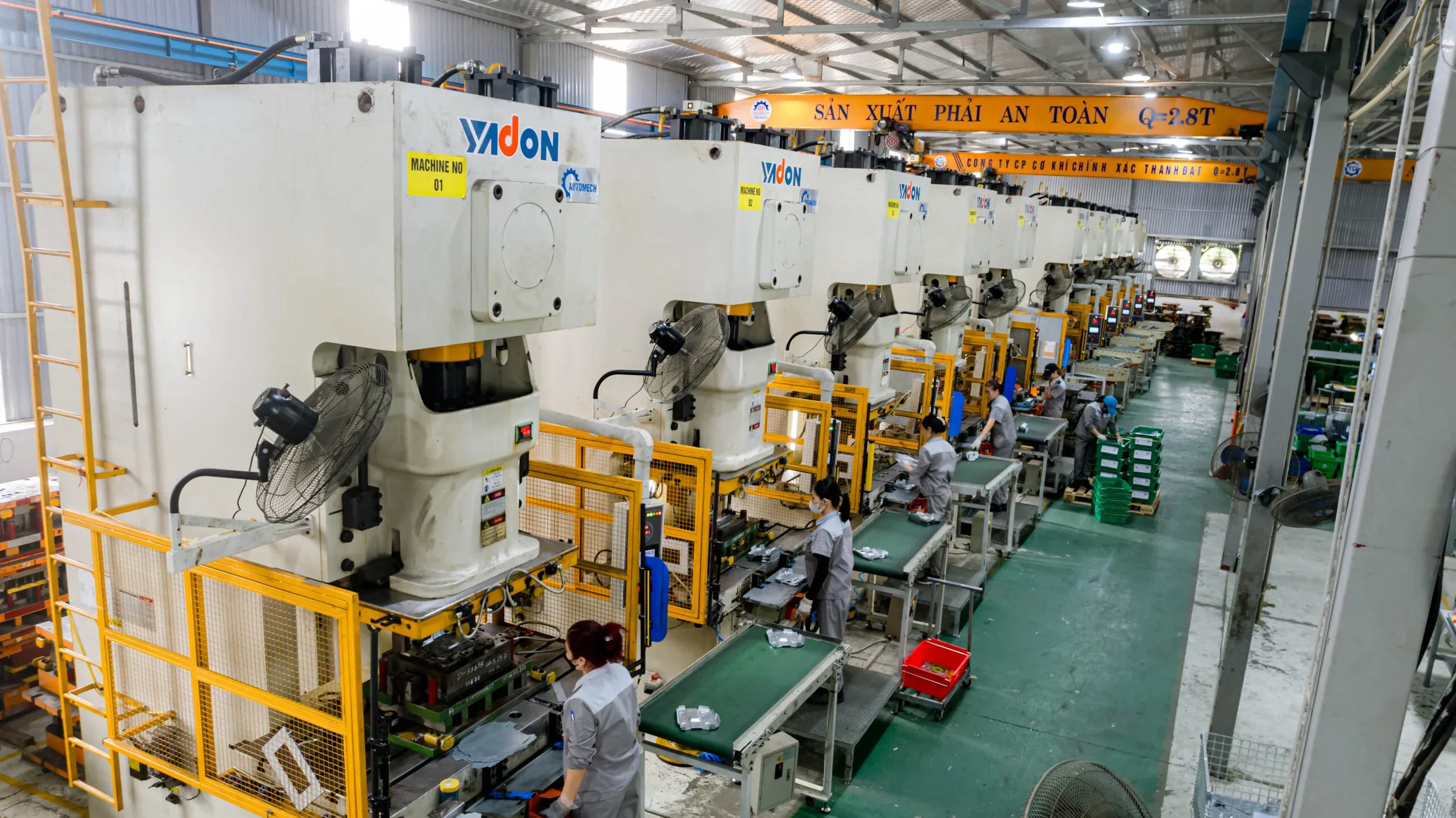
Automech provides advanced turnkey solutions for mass-producing high-precision OEM metal stamping parts
13.1 What are OEM metal stamping parts?
13.1.1 Definition and typical applications
OEM metal stamping parts are custom-engineered metal components cold-formed from sheet metal coils or flat blanks by a contract manufacturer specifically for integration into an Original Equipment Manufacturer’s finished product. Typical applications include automotive body-in-white (BIW) reinforcements, chassis brackets, motor mounts, EV battery module enclosures, and industrial machinery housings.
13.2 What types of parts can be produced through OEM metal stamping?
13.2.1 Automotive brackets, structural parts, and sheet metal components
OEM stamping produces a wide range of components, including structural mounting brackets, reinforcement plates, crossmembers, splash guards, heat shields, seat recliner plates, copper/aluminum EV busbars, and precision electrical terminals.
13.3 What materials are used for OEM metal stamping parts?
13.3.1 Steel, stainless steel, galvanized steel, AHSS, and aluminum
Common stamping materials include commercial cold-rolled steel (SPCC), deep-drawing steel (SPCE), stainless steel (SUS304, SUS409), electro- and hot-dip galvanized steel (SECC, SGCC), Advanced High-Strength Steels (AHSS, Dual-Phase), structural aluminum alloys (5052, 6061-T4/T6), and copper/brass alloys.
13.4 What is the difference between OEM metal stamping and standard stamping?
13.4.1 Specifications, tooling, quality, documentation, and traceability
Standard metal stamping produces generic, catalog-based components with wide tolerances using non-proprietary tooling. OEM metal stamping manufactures parts strictly to customer proprietary 2D/3D engineering specifications using dedicated, customer-owned dies, backed by full Level 3 PPAP documentation, certified quality systems (IATF 16949 / ISO 9001), and complete multi-year lot traceability.
13.5 How accurate are OEM metal stamping parts?
13.5.1 Factors affecting stamping tolerances and dimensional accuracy
Precision OEM metal stamping achieves linear and diametrical tolerances between ± 0.005 mm and ± 0.02 mm, while general structural stampings hold tolerances of ± 0.05 mm to ± 0.15 mm. Dimensional accuracy is governed by toolroom machining precision (wire EDM), punch-to-die clearances, press ram rigidity, springback compensation design, and material gauge uniformity.
13.6 How do I choose an OEM metal stamping supplier?
13.6.1 Technical, quality, tooling, capacity, and sourcing criteria
Select an OEM stamping supplier based on press tonnage range (100T to 1,300T+), in-house wire EDM toolroom assets, active IATF 16949 and ISO 9001 quality certifications, climate-controlled CMM inspection labs, upfront DFM engineering support, robotic welding capabilities, and proven experience in export logistics and packaging.
13.7 How do I request an OEM metal stamping RFQ?
13.7.1 Required drawings, CAD files, materials, volumes, and quality specifications
To receive an accurate quotation, submit your 3D CAD files (STEP/IGES) and 2D engineering drawings (PDF) detailing critical tolerances, hole locations, and GD&T datums. Specify exact raw material alloy grades, sheet thickness, required surface treatments, secondary assembly requirements, annual volume forecasts, delivery milestones, and quality documentation requirements (such as Level 3 PPAP).
13.8 Why source OEM metal stamping parts from Vietnam?
13.8.1 Cost, manufacturing capability, export readiness, and supply-chain diversification
Vietnam offers competitive production and toolmaking costs, modern pressworking infrastructure, skilled mechanical engineering talent, and favorable export logistics through direct deep-water maritime shipping routes. Sourcing from Vietnam provides global OEMs with a dependable, high-capability manufacturing alternative that mitigates trade risks under corporate “China+1” supply chain diversification strategies.
Automech Mechanical Equipment and Solutions Joint Stock Company
Head Office: No. 285 Phuc Loi Street, Phuc Loi Ward, Hanoi City
Da Nang Branch: No. 20 Nguyen Sinh Sac Street, Hoa Khanh Ward, Da Nang City
Ho Chi Minh Branch: No. 84, Street No. 10, Van Phuc Urban Area, Hiep Binh Ward, Ho Chi Minh City
Factory No. 1: Automech Automation Equipment, Mold & Tool Manufacturing Factory – Automech Demo Center: Dinh Tram Industrial Park, Nenh Ward, Bac Ninh City, Vietnam
Factory No. 2: Automech Parts Manufacturing & Component Fabrication Factory: Viet Nhat Industrial Cluster, Xuan Cam Commune, Bac Ninh City, Vietnam
Hotline: 0987 899 347
Website: https://automechmfg.com/
Fanpage: https://www.facebook.com/automech.mfg/
YouTube: https://www.youtube.com/@Automechmfg