The B pillar of a car is one of the most critical structural components in modern vehicle architecture. Positioned between the front and rear door openings, it connects the roof rail to the rocker panel, forming a central vertical load path within the Body-in-White (BIW) structure. Beyond hosting door latches, hinges, and seatbelt anchors, the B-pillar plays a vital role in side-impact crash safety, rollover protection, and overall body rigidity. In this comprehensive technical guide, we examine the design, materials, manufacturing processes, and BIW integration of automotive B-pillars, along with key sourcing strategies for global OEMs and Tier suppliers.
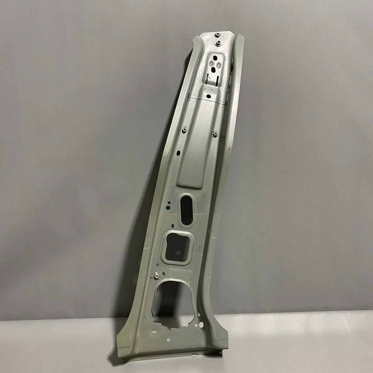
Stamped Automotive B-Pillar Reinforcement Structure
1. What Is the B-Pillar of a Car?
1.1 B-Pillar Definition
1.1.1 What is the B-pillar of a car?
The B-pillar of a car is the vertical structural support pillar located in the midsection of a vehicle body. It stands between the front side window and the rear side window (or rear door frame). In closed-body passenger vehicles—such as sedans, SUVs, crossovers, and trucks—it spans from the floor panel/rocker assembly up to the roof frame.
1.1.2 B-pillar meaning in automotive body structure
In automotive body engineering, pillars are closed-section structural uprights designated alphabetically from front to rear (A, B, C, and sometimes D). The B-pillar acts as a central tie-bar that prevents body collapse during side-impact events (such as FMVSS 214 or Euro NCAP side pole tests) and maintains cabin integrity during vehicle rollovers.
1.1.3 Difference between car B-pillar and B-pillar car terminology
- Car B-pillar: Refers to the physical stamped/welded structural assembly installed on the side structure of a vehicle.
- B-pillar car terminology: Refers to the design classification or architectural layout of the vehicle body (e.g., standard “B-pillar design” vs. “hardtop / pillarless design,” where the B-pillar is eliminated for aesthetic reasons, requiring heavy floor and roof reinforcement).
1.2 Where Is the B-Pillar Located?
1.2.1 B-pillar position between the front and rear doors
The B-pillar is centrally positioned along the side frame. It forms the rear edge frame for the front door aperture and the leading edge frame for the rear door aperture.
1.2.2 B-pillar connection to the vehicle side body
It is integrated into the inner and outer side-frame assemblies, acting as the primary anchor point for:
- Front door striker/latch mechanisms.
- Rear door support hinges (on front-hinged rear door designs).
- B-pillar trim, weatherstrips, and secondary seals.
1.2.3 B-pillar relationship with roof rail and rocker panel
- Upper Interface: Welded directly to the roof rail outer/inner reinforcement.
- Lower Interface: Flared outwards to form a broad load-distributing base that welds onto the rocker panel (side sill).
1.3 B-Pillar in the Overall Vehicle Body Structure
1.3.1 B-pillar within the Body-in-White structure
Within the unpainted, fully welded sheet-metal frame known as the Body-in-White (BIW), the B-pillar bridges the floor pan assembly with the upper ring frame, transforming two horizontal structures into a rigid 3D box structure.
1.3.2 Relationship with side body structure
The B-pillar anchors the outer side frame stamping to the inner side body structure, forming a hollow, closed-box section that maximizes resistance to bending and torsion.
1.3.3 Relationship with cross members and car beam structures
To transfer side crash energy across the vehicle without crushing the passenger compartment, the lower B-pillar connects directly to floor cross members, while the upper structure ties into roof cross members or Cross Car Beams (CCB).
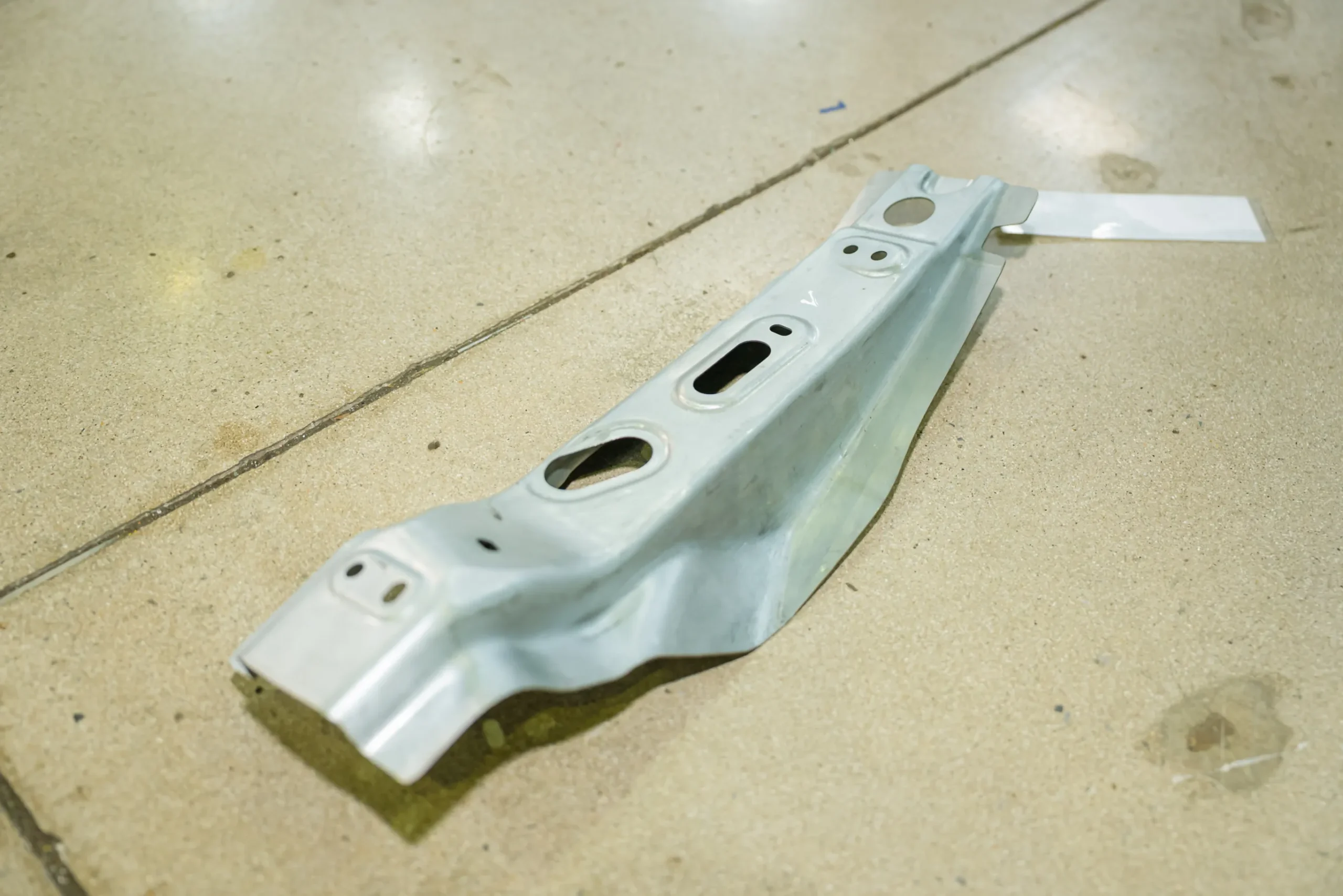
Stamped High-Strength Steel Automotive Reinforcement Component
2. A-Pillar vs B-Pillar vs C-Pillar
2.1 A-Pillar
2.1.1 Location and structural role
Located on either side of the front windshield, the A-pillar anchors the front door hinges, absorbs frontal impact energy, and supports windshield glass installation.
2.1.2 Relationship with windshield and roof structure
It channels frontal crash loads from the upper shotgun/fender rails back into the roof structure and floor frame, protecting the front occupants during offset frontal impacts.
2.2 B-Pillar
2.2.1 Location and primary structural functions
Located between the front and rear doors, its primary role is absorbing lateral forces during side collisions and supporting vertical forces during vehicle rollovers.
2.2.2 Relationship with front and rear door openings
It dictates the structural tolerance and flushness of both door seals, playing a key role in reducing Wind Noise (NVH) and preventing water ingress.
2.3 C-Pillar
2.3.1 Location and structural role
Located behind the rear side doors, the C-pillar frames the rear windshield and supports the rear roof section. (Note: On SUVs, minivans, and station wagons, a D-pillar exists behind the C-pillar).
2.3.2 Relationship with rear body and roof structure
It absorbs rear-impact loads and ties the rear wheel house/quarter panel assembly into the roof structure.
2.4 A-Pillar vs B-Pillar vs C-Pillar Comparison
| Feature / Criteria | A-Pillar | B-Pillar | C-Pillar |
| Primary Location | Sides of front windshield | Between front & rear doors | Behind rear doors / sides of rear window |
| Primary Crash Role | Frontal crash & roof crush | Side-impact protection & roof crush | Rear impact load transfer & roof support |
| Primary Load Directions | Longitudinal (X-axis) & Vertical (Z-axis) | Transverse (Y-axis) & Vertical (Z-axis) | Longitudinal (X-axis) & Vertical (Z-axis) |
| Key Safety Functions | Driver visibility maintenance, airbag deployment framing | Side curtain airbag support, belt anchor points, latch retention | Rear passenger head protection, fuel tank shield load path |
| Typical Materials | AHSS / Hot-stamped Boron Steel | Ultra High-Strength Steel (UHSS), Press Hardened Steel (PHS) | High-Strength Steel (HSS), Dual-Phase Steel (DP) |
3. Functions of the B-Pillar in Vehicle Structure
3.1 Structural Functions
3.1.1 Supporting the roof and side body structure
The B-pillar supports roof loads, preventing sag under static load conditions and maintaining vertical body geometry.
3.1.2 Maintaining body structural stiffness
It significantly enhances the vehicle’s static and dynamic torsional stiffness (measured in Nm/degree, minimizing body flex during cornering or traversing uneven terrain.
3.1.3 Transferring loads through the vehicle body
It acts as a load distributor, redirecting dynamic roof and side forces into the underbody chassis structure.
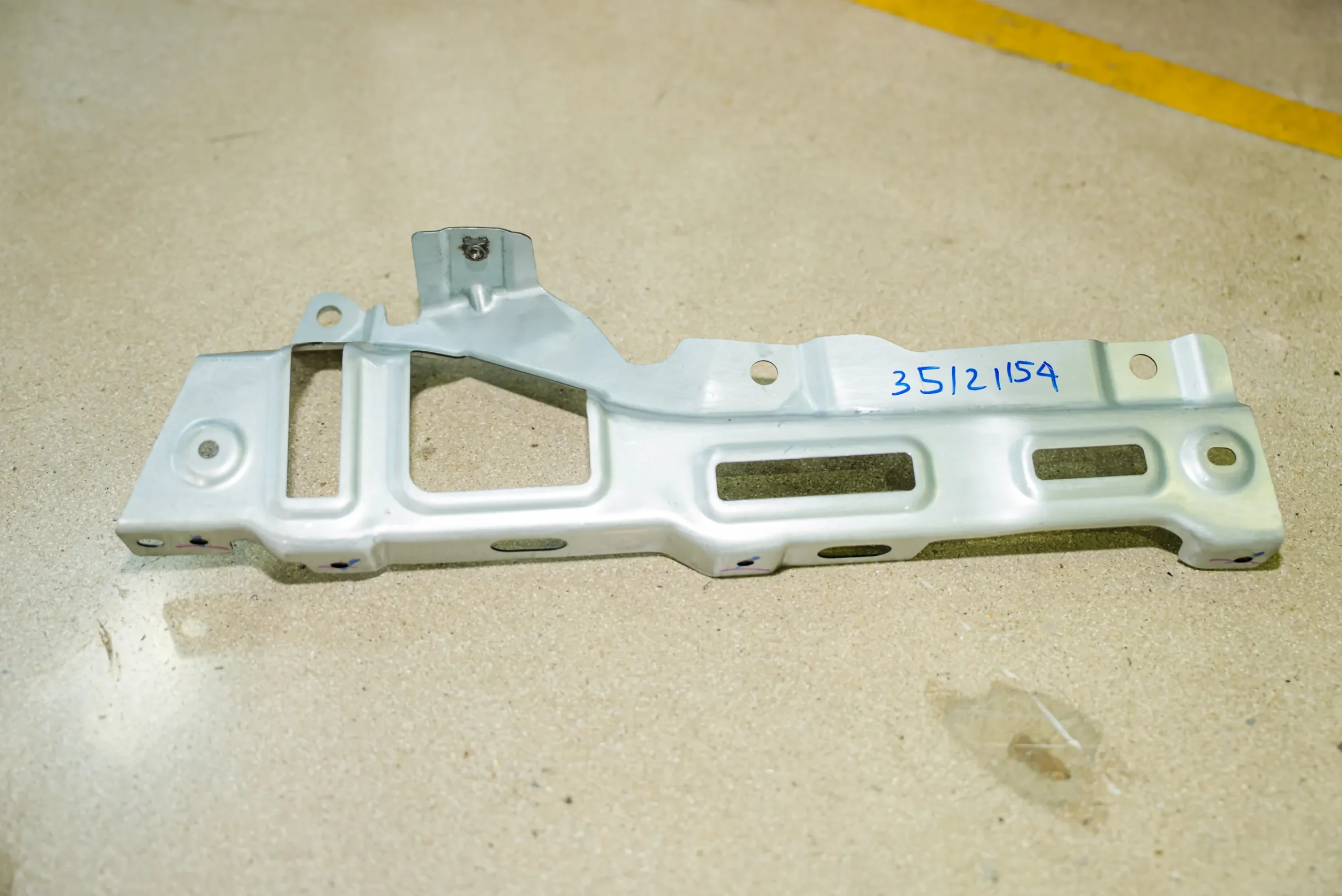
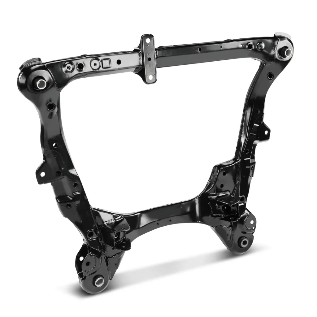
Stamped Automotive Structural Component with Integrated Weld Nut
3.2 B-Pillar and Vehicle Safety
3.2.1 Role in side-impact structural performance
In side collisions, the intruder vehicle or pole directly impacts the side structure. The B-pillar must resist excessive intrusion into the passenger cabin, providing room for side airbags to deploy effectively.
3.2.2 Relationship with occupant protection systems
- Anchors the front three-point seatbelt D-ring and retractor mechanism.
- Houses side-curtain airbag channels and side-impact sensors (accelerometers/pressure sensors).
3.2.3 Crashworthiness and structural load management
Modern B-pillars feature tailored properties (tailor-welded or tailor-heated blanks), where the upper section is extremely hard (1500MPa) to resist intrusion, while the lower section exhibits higher ductility to absorb energy through controlled bending.
3.3 B-Pillar and Body Rigidity
3.3.1 Connection with rocker panels
The broad lower flange connects to the heavy-gauge rocker panel, creating a wide joint node that resists bending forces.
3.3.2 Connection with roof rails
The upper flange interfaces with the roof rail outer and inner reinforcements, locking the upper ring frame.
3.3.3 Connection with door frames and structural reinforcements
Integrated stiffeners within the B-pillar frame reinforce the door hinge and latch mounting areas, preventing door latch detachment during dynamic impacts.
3.4 B-Pillar Load Paths
3.4.1 Vertical load paths
Channels vertical crushing forces directly down to the rocker panel during rollover events (conforming to IIHS Roof Crush Standards).
3.4.2 Lateral load paths
Distributes side forces along the Y-axis across the underbody cross members and top roof cross members.
3.4.3 Interaction with cross member structures
Without an underlying floor cross member, lateral forces on the B-pillar would cause the floor pan to buckle inward. The B-pillar and floor cross member act together as a single continuous load frame.
4. B-Pillar Construction and Materials
4.1 B-Pillar Construction
4.1.1 Inner and outer B-pillar structures
A standard automotive B-pillar is a multi-piece stamped assembly comprising:
- B-Pillar Outer: Forms part of the visible exterior side-body panel, requiring high surface quality (Class-A surface stamping).
- B-Pillar Inner: Formed from stamped sheet metal, facing the vehicle interior to provide attachment points for interior trim and wiring harnesses.
4.1.2 Reinforcement components
A thick B-Pillar Reinforcement layer is sandwiched between the inner and outer shells. This part is usually stamped from Ultra High-Strength Steel (UHSS) or Press-Hardened Steel (PHS).
4.1.3 Structural joining and assembly points
The inner, reinforcement, and outer layers are joined along double-flanged edges using Resistance Spot Welding (RSW), laser welding, or structural adhesives.
4.2 Materials Used for Automotive B-Pillars
4.2.1 High-Strength Steel (HSS)
Conventional HSS grades (such as micro-alloyed steels) with yield strengths between 280MPa and 450MPa are used for non-critical inner panels or light-duty vehicles.
4.2.2 Advanced High-Strength Steel (AHSS)
Grades like Dual-Phase (DP780, DP980) and Complex-Phase (CP) steel combine formability with tensile strengths up to 1000MPa, making them suitable for structural inner parts and reinforcements.
4.2.3 Ultra High-Strength Steel (UHSS), Press Hardened Steel (PHS)
Boron steel alloys (22MnB5) subjected to hot stamping reach ultimate tensile strengths of 1500MPa to 2000MPa. PHS is widely used for B-pillar reinforcement structures.
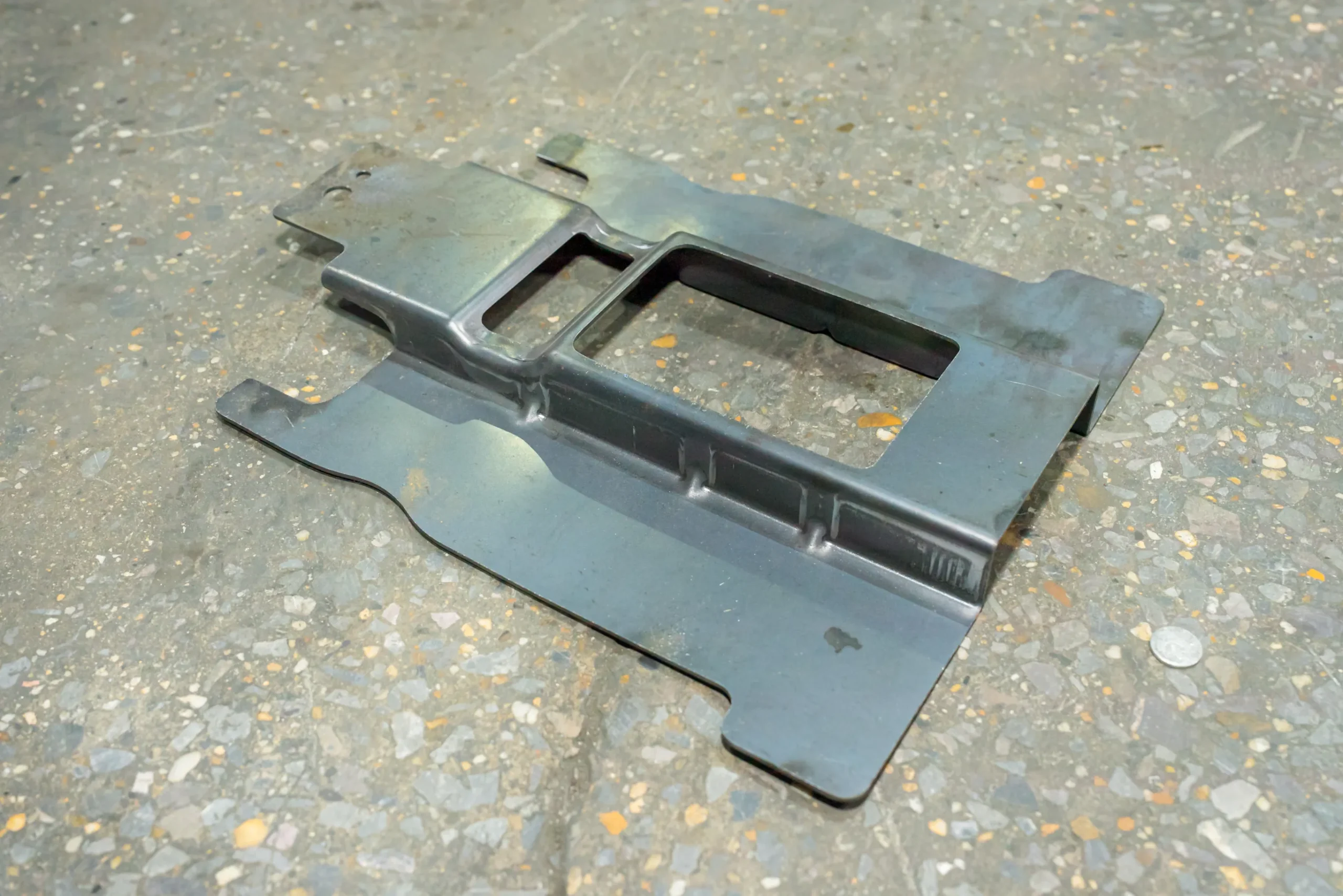
Precision Stamped Metal Component for Vehicle Body Assembly
4.3 Material Selection Criteria
4.3.1 Strength-to-weight ratio
Maximizing tensile yield strength while minimizing sheet gauge thickness (t1.2mm-2.0mm) lowers overall vehicle mass.
4.3.2 Formability
Complex deep-drawn shapes require high elongation during stamping. Cold stamping AHSS can lead to springback challenges, whereas hot stamping PHS eliminates springback completely.
4.3.3 Crashworthiness requirements
Materials are selected based on energy absorption capacity (MJ/m3) and resistance to fracture under high strain rates during collisions.
4.3.4 Corrosion resistance and surface treatment
Steel sheets are coated with Zinc (electro-galvanized or hot-dip galvanized – GI/GA) or Aluminum-Silicon (AlSi coatings on PHS) to prevent rust throughout the vehicle’s lifespan.
4.4 B-Pillar Lightweighting
4.4.1 Reducing structural mass
Replacing conventional steel (1.8mm-2.5mm) with UHSS/PHS (1.2mm-1.6mm) reduces component mass by up to 30% while improving intrusion resistance.
4.4.2 Material optimization
Using Tailored Blanks (Tailor Welded Blanks – TWB, or Tailor Rolled Blanks – TRB) allows engineers to vary material thickness and grade across the length of a single B-pillar.
4.4.3 Lightweighting versus structural stiffness
Engineers use Finite Element Analysis (FEA) and topology optimization to remove excess material without sacrificing torsional stiffness or acoustic performance.
5. How Is an Automotive B-Pillar Manufactured?
5.1 B-Pillar Manufacturing Process Overview
5.1.1 Engineering and material specification
Defining component geometry, material grade, blank thickness, performance requirements, and DFM (Design for Manufacturability) parameters.
5.1.2 Blank preparation
Coiled steel is uncoiled, leveled, and cut into optimized blank shapes. For TWBs, laser welding joins different steel grades or sheet thicknesses into a single flat blank before forming.
5.1.3 Forming and stamping
Blanks are fed into automated tandem press lines or hot stamping lines to shape the B-pillar profile.
5.1.4 Welding and assembly
The inner panel, reinforcement, and mounting brackets are joined using automated robotic welding cells.
5.1.5 Dimensional inspection and quality validation
Components are checked using Coordinate Measuring Machines (CMM), 3D optical scanners, and destructive weld teardown tests.
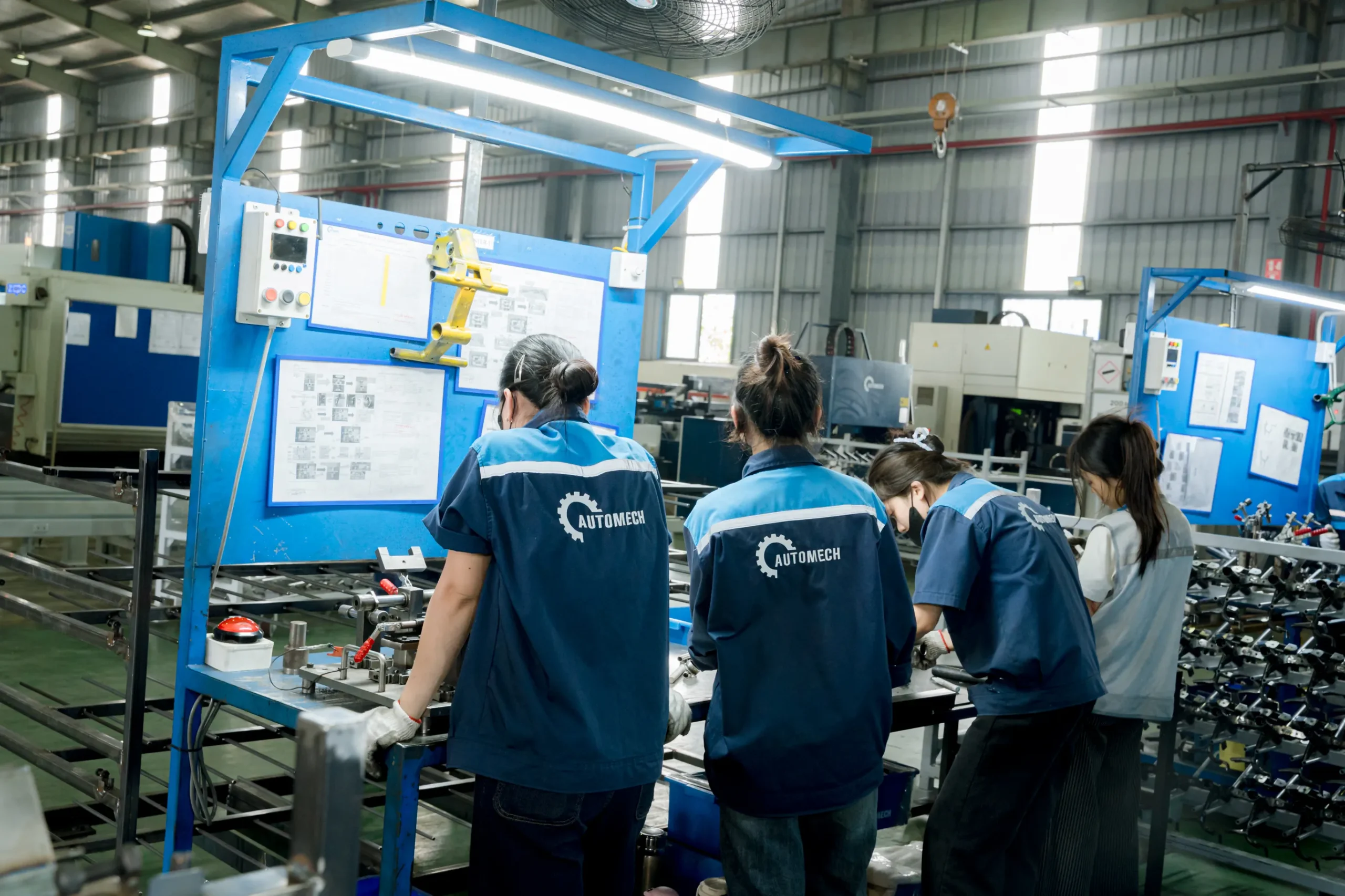
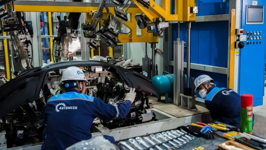
Technicians Conducting Quality Assembly and Inspection of Stamped Components
5.2 B-Pillar Stamping Process
5.2.1 Blanking
Shearing flat metal sheets into targeted geometric blanks to reduce scrap material during forming.
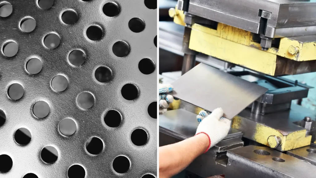
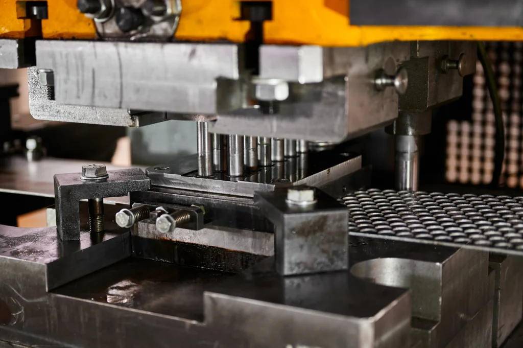
5.2.2 Piercing
Creating mounting holes, datum locator holes, and wiring access points using high-tonnage mechanical or hydraulic presses.
5.2.3 Bending
Forming flanges, edge stiffeners, and profile contours along defined bend axes.
5.2.4 Deep drawing where applicable
Pressing sheet metal deep into die cavities to form the main structural channel of the outer or inner B-pillar shell.
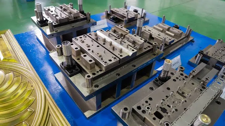
5.2.5 Automotive stamping die requirements
Automotive stamping dies require hardened tool steel inserts (e.g., SKD11, DC53, Cr12MoV), PVD surface coatings, and cast iron press bolsters to withstand continuous high-tonnage production.
5.3 B-Pillar Forming Technologies
5.3.1 Cold stamping
- Performed at ambient temperatures using mechanical or servo presses (800tons-2500tons).
- Best suited for low-to-medium strength steel inner/outer panels (up to DP980).
- Requires multiple die stations (Draw, Trim, Flange, Restrike).
5.3.2 Hot stamping (Press Hardening Technology – PHT)
- Boron steel blanks (22MnB5) are heated in a roller hearth furnace to austenitizing temperatures (~900°C – 950°C).
- The heated blank is quickly transferred by robot into a chilled press die.
- The die closes to form the part and rapidly quenches it at rates exceeding 30°C/sec.
- The microstructural transformation to fully martensitic steel yields tensile strengths between 1500MPa and 2000MPa with virtually zero springback.
5.3.3 Metal forming considerations for AHSS and UHSS
- Cold stamping AHSS requires higher press tonnage and causes increased die wear.
- Hot stamping requires specialized 3D 5-axis laser trimming machines because the hardened material rapidly wears down mechanical trimming dies.
5.4 Stamping Die and Tooling Requirements
5.4.1 Die design and forming simulation
Forming simulation software (e.g., AutoForm, PAM-STAMP) models material thinning, wrinkle formation, and stress distributions before physical steel cutting begins.
5.4.2 Springback control
For cold-stamped AHSS, tooling designers apply springback compensation techniques to the CAD surfaces (e.g., over-bending profiles) to ensure finished parts match specifications.
5.4.3 Tool wear and dimensional consistency
Using premium tool steels, high-lubrication drawing compounds, and automated die maintenance schedules extends tooling life over multi-year production runs.
6. B-Pillar Welding and BIW Assembly
6.1 B-Pillar Welding Processes
6.1.1 Resistance Spot Welding (RSW)
The most common joining method in BIW. High electric current creates localized fusion nuggets joining 2-ply or 3-ply sheet metal layers (Outer + Reinforcement + Inner).
6.1.2 MIG/MAG welding
Gas Metal Arc Welding (GMAW) is used for attaching heavy mounting brackets, thick structural reinforcements, or localized structural joints.
6.1.3 Laser welding and laser brazing
Used to create continuous, narrow-width joints along outer door frames. Reduces flange width, saves material weight, and improves joint stiffness compared to discrete spot welds.
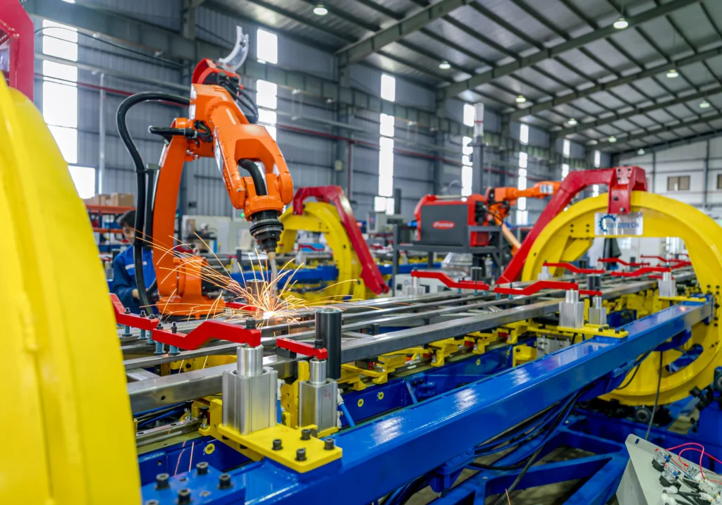
6.1.4 Robotic welding
Fully automated 6-axis industrial robots equipped with servo-driven welding guns ensure consistent spot size, electrode pressure, and cycle times.
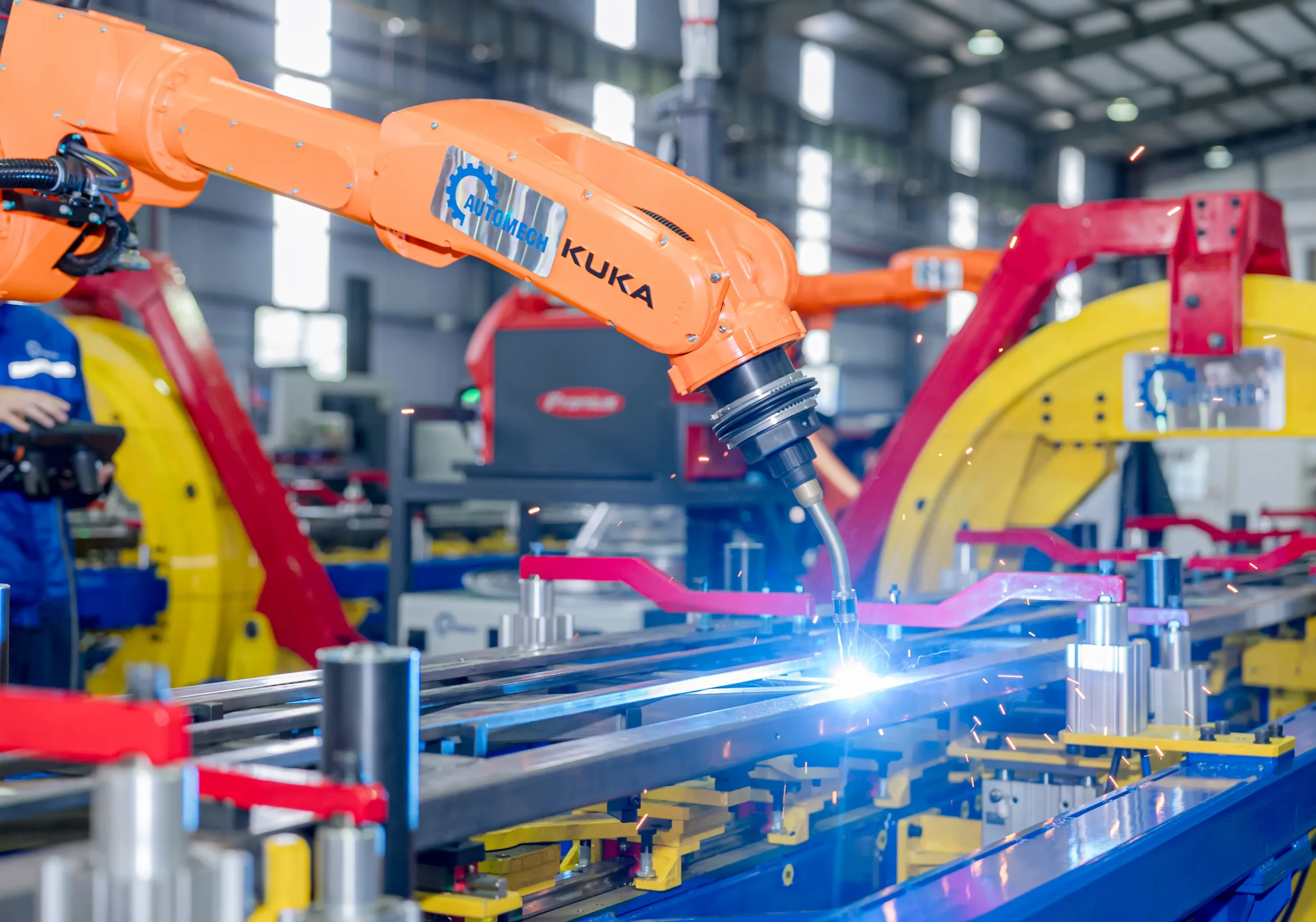
Automated KUKA Robotic Arm Performing Precision Welding on Automotive Assemblies
6.2 B-Pillar Assembly
6.2.1 Joining inner and outer structural components
Inner panels, structural reinforcements, and outer shells are clamped together in precise sequence to maintain geometry.
6.2.2 Installation of reinforcement components
Internal structural plates, seatbelt anchor nuts, and door hinge backing plates are projection-welded to the inner reinforcement before enclosing the assembly.
6.2.3 Welding sequence and distortion control
Optimizing weld sequence paths balances thermal expansion during spot welding, preventing thermal warping and preserving final part geometry.
6.3 Welding Fixtures and Positioning
6.3.1 Automotive welding fixtures
Custom electro-pneumatic assembly fixtures hold loose stamped parts securely during robotic welding cycles.
[ Pneumatic Clamps ] —> Holds Sheet Contours Rigid
[ Hardened Locating Pins ] ——+—–> Engages RPS Datum Holes
[ Copper Backings ] —-> Prevents Weld Arc Flashing
6.3.2 Part positioning and clamping
Fixtures align components using designated Reference Point System (RPS) locator holes and net-shape block pads.
6.3.3 Fixture repeatability and dimensional control
High-precision fixture manufacturing ensures repeatable part placement within tight tolerances (0.2mm to 0.5mm).
6.4 B-Pillar in Body-in-White Manufacturing
6.4.1 BIW welding assembly
The B-pillar sub-assembly transfers from the sub-line into the main BIW side-frame framing line.
6.4.2 Integration into the vehicle side body
Framing robots position the left and right side-outer sub-assemblies against the floor pan and roof structure, spot-welding them into a rigid 3D cage.
6.4.3 Automated BIW production lines
Modern automotive assembly lines use vision-guided positioning, automated guided vehicles (AGVs), and multi-robot framing cells to achieve cycle times below 60 seconds per chassis.
7. B-Pillar Connections With Cross Members and Body Structures
7.1 B-Pillar and Cross Member Frame
7.1.1 What is a cross member on a car?
A cross member is a transverse structural beam spanning the vehicle chassis (left-to-right). It reinforces the floor pan, frame rails, or roof frame against lateral structural loads.
7.1.2 Crossmember of a car and structural load transfer
Floor cross members form lower structural bridges across the vehicle interior. During a side collision, the cross member acts in compression, preventing the side impact force on the B-pillar from crushing the cabin.
7.1.3 Relationship between B-pillar and cross member frame
The base of the B-pillar welds into the rocker panel directly opposite a major floor cross member node, creating a continuous, unyielding lateral load path.
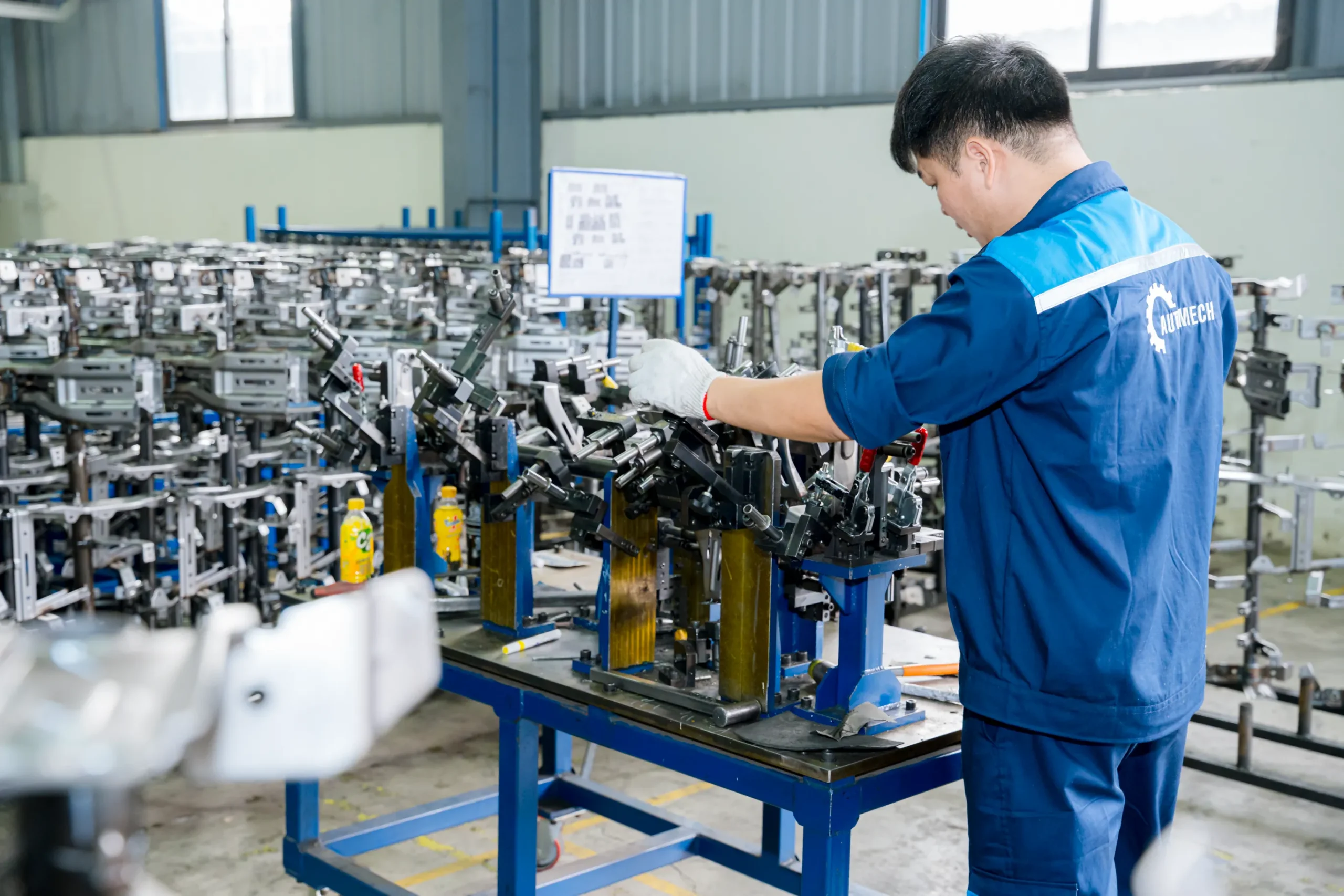
Engineer Adjusting Welding Fixtures for Automotive Component Fabrication
7.2 B-Pillar and Cross Car Beam
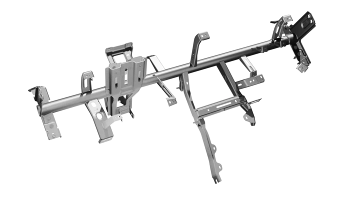
7.2.1 What is a Cross Car Beam?
A Cross Car Beam (CCB) is a major structural assembly located beneath the instrument panel (dashboard). It supports the steering column, HVAC unit, airbags, and passenger glove box while providing lateral structural stiffness between the front A/B-pillar node zones.
7.2.2 Cross Car Beam versus other automotive cross members
- Floor Cross Members: Welded directly to the underbody floor pan to handle chassis and side-impact loads.
- Roof Cross Members: Span upper roof rails to support roof sheet metal and absorb rollover loads.
- Cross Car Beam: A multi-functional structural module located inside the dashboard area, constructed from steel tubing, stamped aluminum, or magnesium die-castings.
7.2.3 Structural relationship between B-pillar and cross car beam systems
While the CCB sits primarily between the A-pillars, it routes side-impact loads along the front cowl zone, distributing torsional loads back into the main floor rails and side-frame B-pillar assemblies.
7.3 B-Pillar and Rocker Panel
7.3.1 Lower B-pillar connection
The wide bottom section of the B-pillar outer and reinforcement wraps over the inner and outer rocker panel channels.
7.3.2 Load transfer through the rocker structure
Impact forces travel downward through the B-pillar into the rocker panel, which distributes the load forward to the front wheel house and rearward to the rear longitudinal frame rails.
7.3.3 Dimensional requirements at the joining interface
The interface gap between the rocker panel and lower B-pillar must remain consistent (0.8mm) to enable reliable automated spot welding and structural adhesive bonding.
7.4 B-Pillar and Roof Structure
7.4.1 Upper B-pillar connection
The top section of the B-pillar flares into a T-shape that interfaces with the longitudinal roof rail profile.
7.4.2 Roof rail integration
Multiple spot welds secure the B-pillar reinforcement to the outer roof rail, creating a rigid upper corner node.
7.4.3 Structural continuity through the side body
This continuous connection creates an unbroken structural loop—from floor cross member to rocker, up through the B-pillar, across the roof rail/cross member, and down the opposite B-pillar.
8. B-Pillar Manufacturing Challenges and Quality Control
8.1 Dimensional Accuracy and Tolerance
8.1.1 Critical dimensions and joining interfaces
Strict tolerances are required for door hinges, door strikers, glass run channels, and surrounding weatherstripping to prevent door sagging, water leaks, and wind noise.
8.1.2 Stamping dimensional variation
Variations in raw material coil thickness, tensile yield strength, and press oil lubrication can alter forming results across production batches.
8.1.3 Springback and deformation control
When stamping high-strength steels, elastic recovery (springback) can cause part walls to flex inward or twist out of tolerance. Corrective measures include springback compensation in die surfaces, restriking steps, or transitioning to hot stamping.
8.2 Welding Quality and Assembly Accuracy
8.2.1 Welding distortion
Excessive heat input during spot welding or MIG welding can warp thin sheet metal panels. Controlled clamp pressure and optimized welding sequences help minimize thermal distortion.
8.2.2 Fixture positioning accuracy
Worn locating pins or contamination inside fixture clamps can shift part alignment, leading to out-of-tolerance BIW sub-assemblies.
8.2.3 Weld consistency and repeatability
Automated welding controllers monitor current, voltage, pressure, and dynamic resistance in real time to prevent cold welds, burn-through, or undersized weld nuggets.
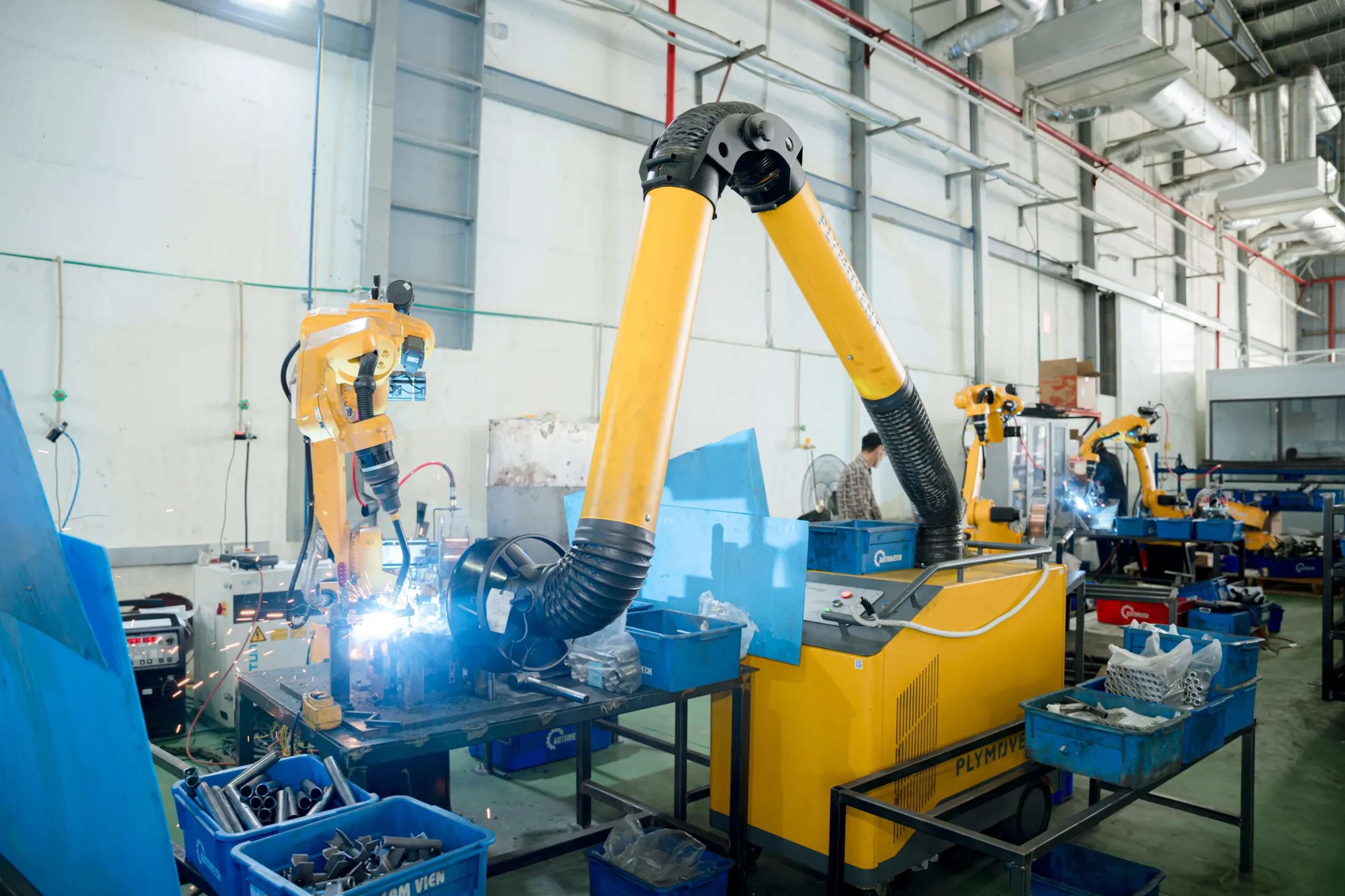
Robotic Welding Station Integrated with Plymovent Industrial Fume Extraction System
8.3 Dimensional Inspection
[ CMM Touch-Probe Measurement ] —-> Inspects Precise Hole Coordinates (± 0.05 mm)
[ 3D Laser Optical Scanning ] ——-> Generates Full Surface Contour Heat-maps
[ Checking Fixtures (Go/No-Go) ] —–> Fast Shop-Floor Line Gauge Verification
8.3.1 CMM inspection
Coordinate Measuring Machines (CMM) use touch probes to verify critical hole locations, surface contours, and datum edges against native CAD models.
8.3.2 Fixture-based inspection
Shop-floor checking fixtures with digital dial indicators and Go/No-Go pin gauges enable rapid line-side verification of stamped parts.
8.3.3 Measurement of critical assembly points
Key feature points—such as seatbelt anchorage holes and door latch mountings—are 100% inspected using automated vision systems on the production line.
8.4 Quality Management
8.4.1 Material traceability
Heat numbers, coil certs, and material lot codes are tracked through every step of blanking, stamping, and assembly.
8.4.2 Process control
Statistical Process Control (SPC) tracks key quality metrics (Cpk1.67) across press shop operations and welding assembly lines.
8.4.3 Corrosion protection and surface treatment
Assembled BIW structures pass through electrocoating (E-Coat / KTL) immersion tanks, where phosphate pre-treatment and electro-deposited epoxy primers protect internal box sections from corrosion.
8.4.4 Prototype-to-production quality consistency
Ensuring seamless transitions from soft-tool prototype validation through pre-series pilot builds to full mass production.
9. B-Pillar Design for Safety, Lightweighting, and EVs
9.1 B-Pillar Crash Performance Considerations
9.1.1 Side-impact load management
Engineers design the B-pillar to maintain structural integrity under severe dynamic impacts, working alongside door impact beams to limit cabin intrusion.
9.1.2 Structural deformation considerations
Using tailored hot-stamped steel allows the B-pillar’s upper section to resist bending (1500MPa), while its base deforms in a controlled manner (600MPa-800MPa) to safely absorb impact energy.
9.1.3 Load transfer through connected body structures
The B-pillar transfers kinetic energy into floor cross members, seat frame supports, and roof cross members, dissipating forces across the entire chassis frame.
9.2 Structural Stiffness Optimization
9.2.1 Reinforcement design
Internal bulkheads, embossed ribbing, and variable-thickness reinforcement plates increase local moment of inertia (I) without unnecessarily increasing total weight.
9.2.2 Material distribution
Placing higher strength grades along the outer flanges maximizes section modulus where bending stresses peak during collisions.
9.2.3 Joint and connection optimization
Replacing point welds with continuous structural adhesive beads along flange joints improves joint stiffness by 15-20% and increases fatigue life.
9.3 B-Pillar Lightweighting Strategies
9.3.1 AHSS and UHSS material selection
Upgrading from conventional HSS to UHSS or hot-stamped Boron steel allows for thinner sheet metal gauges, reducing weight while increasing strength.
9.3.2 Geometry optimization
Optimizing cross-sectional geometry (e.g., deeper drawn profiles with ribbed contours) increases section stiffness while maintaining lightweight design principles.
9.3.3 Manufacturing-driven lightweighting
Using Tailor Welded Blanks (TWB) or Tailor Rolled Blanks (TRB) eliminates double-layer overlap plates, trimming weight from non-critical areas.
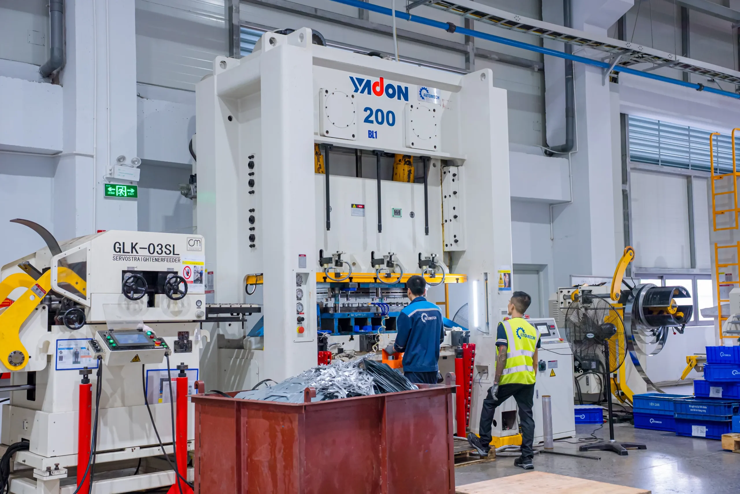
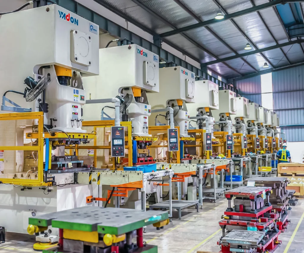
Yadon Heavy-Duty 200-Ton Press Stamping System with Servo Straightener Feeder
9.4 B-Pillar Manufacturing for EVs
9.4.1 Lightweighting requirements for electric vehicles
Electric Vehicles (EVs) carry heavy battery packs (400kg-700kg). Every kilogram saved in the BIW body frame helps extend overall driving range.
9.4.2 Integration with EV body structures
In EVs, the lower B-pillar connects directly to reinforced side sill extrusions that protect the high-voltage battery tray from lateral intrusion during side impacts.
9.4.3 Balancing mass, stiffness, manufacturability, and safety
EV B-pillars balance extreme tensile strength (to protect high-voltage battery modules from thermal runaway) with low mass and efficient high-volume manufacturability.
10. How to Choose an Automotive B-Pillar Manufacturer
10.1 Key Supplier Evaluation Criteria
10.1.1 Automotive stamping and forming capability
Verify that the supplier operates high-tonnage mechanical, hydraulic, or servo press lines (800tons-2500tons) capable of deep drawing complex structural components.
10.1.2 AHSS and UHSS processing capability
Confirm the supplier has proven experience stamping advanced high-strength steels (DP, CP, TRIP) and managing springback, tooling wear, and shear fracture challenges.
10.1.3 Welding and BIW assembly capability
Assess their robotic assembly line capabilities, including Resistance Spot Welding (RSW), MIG/MAG welding, laser seam welding, and structural adhesive dispensing.
10.2 Engineering and Quality Capabilities
10.2.1 DFM and manufacturing feasibility review
The supplier should offer complete Design for Manufacturability (DFM) support, including springback analysis, drawability modeling, and weld access validation.
10.2.2 Dimensional inspection and CMM capability
The factory floor must feature temperature-controlled CMM inspection rooms, 3D laser scanners, and custom checking gauges to guarantee tight manufacturing tolerances.
10.2.3 Tooling, fixture, and process engineering
In-house tooling design, die maintenance, and welding fixture fabrication ensure faster lead times and quick resolution of engineering changes (ECN).
10.2.4 Prototype-to-mass-production support
The supplier should provide soft-tool prototyping, pilot production runs, PPAP (Production Part Approval Process) submissions, and high-volume mass production.
10.3 OEM and Tier Supplier Requirements
10.3.1 Technical drawing and specification management
Complete fluency with GD&T (Geometric Dimensioning and Tolerancing), CAD exchange formats (STEP, IGES, CATIA), and OEM-specific material specifications.
10.3.2 Quality and traceability requirements
Full compliance with IATF 16949 quality management systems, complete material cert tracking, and full process control data logging.
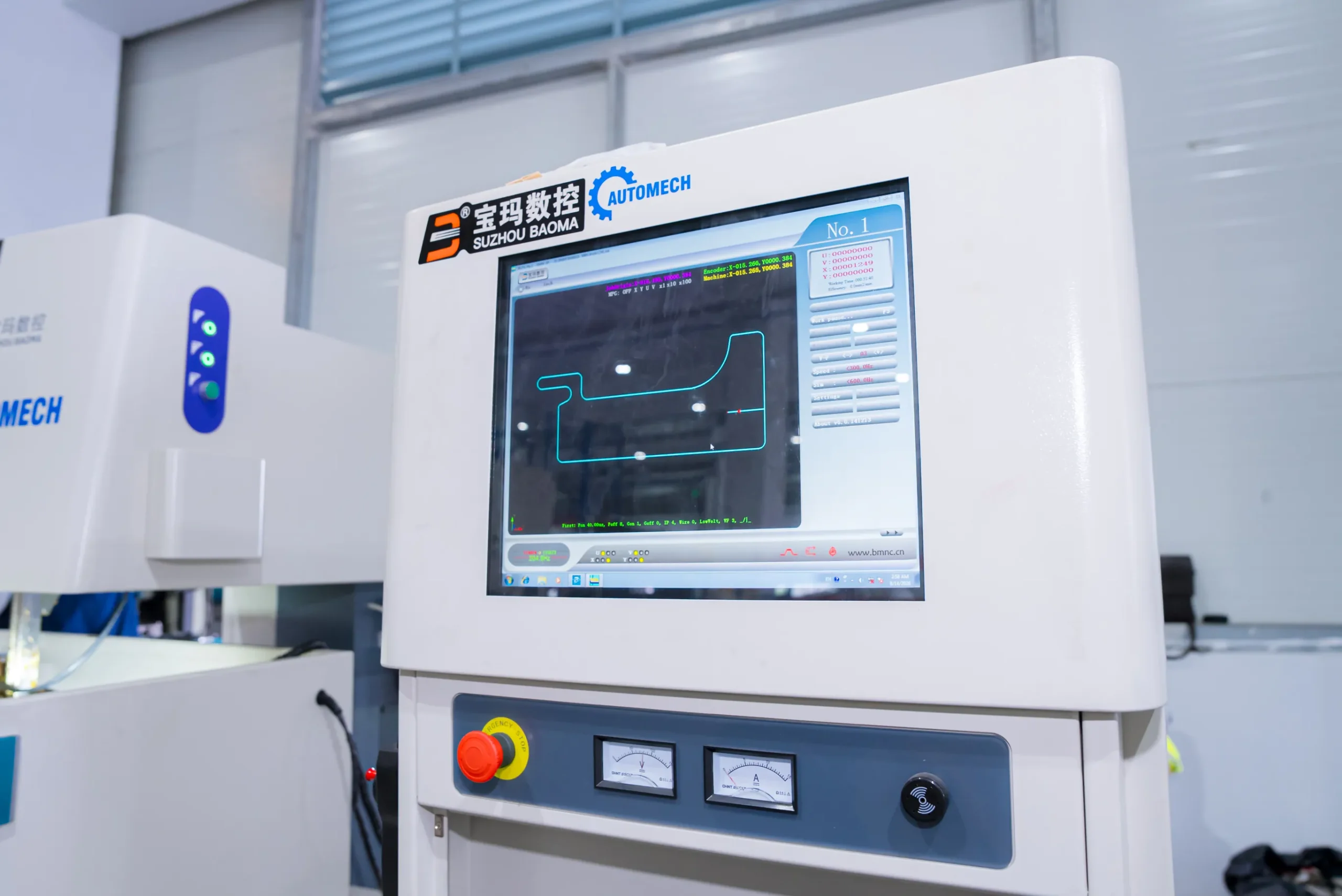
CNC Control Interface for High-Precision Wire EDM Die Processing
10.3.3 Production scalability
Flexible automated assembly cells that can scale production from niche low-volume EV runs to high-volume commercial production schedules.
10.3.4 Export and supply-chain requirements
Proven international logistics capabilities, protective packaging (anti-corrosion VCI paper/bags, custom returnable steel racks), and experience shipping directly to overseas assembly plants.
10.4 Automotive B-Pillar Supplier Due-Diligence Checklist
- IATF 16949 Certification: Valid certification issued by an accredited body.
- Press Capacity: Availability of 800T-2500T stamping press lines.
- Advanced Steel Processing: Demonstrated experience handling AHSS/UHSS materials (>780MPa).
- Robotic Assembly: Fully automated spot welding and structural adhesive application.
- Metrology Equipment: In-house CMM, 3D laser scanners, and dedicated testing fixtures.
- Forming Simulation Software: In-house AutoForm or PAM-STAMP capability.
- International Packaging Standards: Seaworthy, rust-preventative packaging and export logistics experience.
11. Vietnam as an Automotive B-Pillar and BIW Manufacturing Destination
11.1 Vietnam Automotive Manufacturing Ecosystem
11.1.1 Supporting industry development
Vietnam’s industrial manufacturing sector is expanding rapidly, supported by government incentives for automotive manufacturing, precision metal stamping, and high-tech machining.
11.1.2 Automotive parts manufacturing capabilities
Vietnamese manufacturers produce a wide range of automotive structural components, precision metal stampings, welded chassis sub-assemblies, and exterior trim parts for global markets.
11.1.3 OEM and Tier 1/Tier 2 supply opportunities
Major global automakers and Tier 1 suppliers are establishing operations or expanding sourcing partnerships in Vietnam to build resilient, cost-competitive Asian supply chains.
11.2 B-Pillar and Automotive Body Structure Manufacturing in Vietnam
11.2.1 Automotive stamping capabilities
Vietnamese stamping plants feature heavy-tonnage press lines capable of deep drawing, piercing, and blanking structural steel parts to demanding OEM standards.
11.2.2 Welding and assembly capabilities
Modern factories utilize multi-axis industrial robots for Resistance Spot Welding (RSW), MIG/MAG welding, and structural adhesive bonding to deliver complete BIW assemblies.
11.2.3 BIW manufacturing and dimensional inspection
Advanced manufacturing facilities feature climate-controlled CMM inspection labs and automated vision checking systems to maintain strict part dimensional consistency.
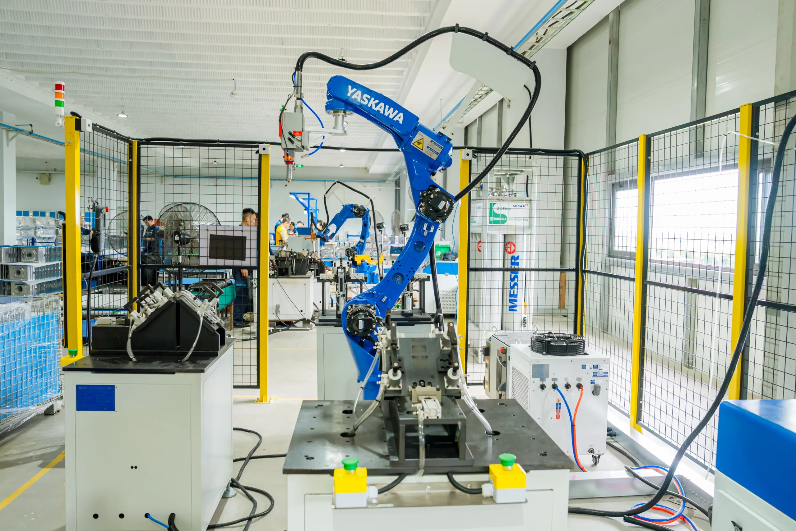
Robotic Welding Workstation Equipped with Yaskawa Industrial Robots for Automotive Manufacturing
11.3 Cross Car Beam and Related Structural Components
11.3.1 Cross Car Beam manufacturing
Vietnamese suppliers manufacture structural tubular and stamped Cross Car Beam assemblies, supporting complex instrument panel structures.
11.3.2 Cross Car Beam stamping
High-precision stamping lines form the structural mounting brackets, steering column supports, and side attachment brackets integrated into Cross Car Beam assemblies.
11.3.3 Cross Car Beam welding assembly
Robotic welding cells perform MIG and spot welding to assemble tubular beams, stamped brackets, and mounting plates into rigid CCB structures.
11.3.4 Cross Car Beam supplier and OEM manufacturing requirements
Suppliers maintain high structural welding standards, tight positional tolerances for steering column mountings, and rigorous anti-vibration performance testing.
11.4 Why Consider a Vietnam Automotive Manufacturing Supplier?
11.4.1 Supply-chain diversification
Sourcing structural stampings and welded BIW assemblies from Vietnam helps global automakers diversify their supply chains and build regional resilience.
11.4.2 Export-oriented manufacturing
Vietnam benefits from extensive international trade agreements (including EVFTA, CPTPP, and RCEP), reducing tariff barriers for exported automotive parts.
11.4.3 Engineering and production scalability
Vietnamese manufacturers offer high-precision engineering, a skilled technical workforce, and scalable production capacities for both niche and high-volume vehicle platforms.
11.4.4 US and European sourcing considerations
Tier 1 and OEM buyers in North America and Europe rely on Vietnamese suppliers for competitive total cost of ownership (TCO), high quality control standards, and reliable international shipping schedules.
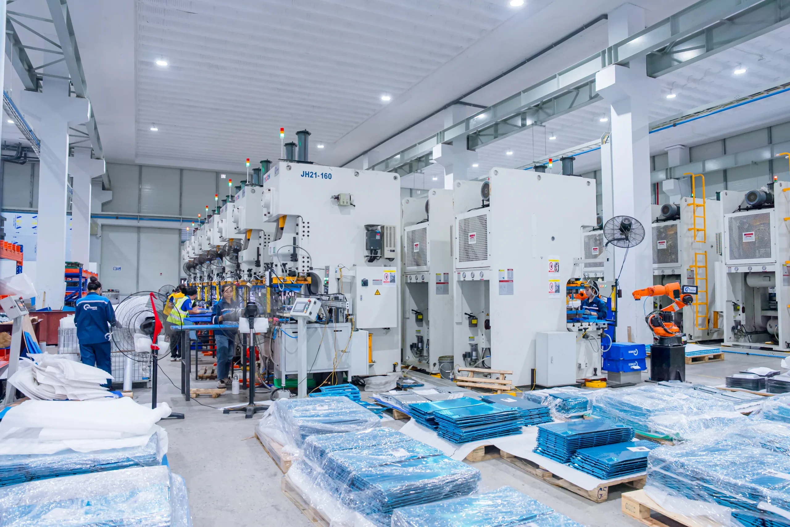
Modern Stamping Workshop with Automated Press Line and Finished Component Inventory
12. Automech Automotive Body Structure Manufacturing & FAQ
12.1 Automotive Body Structure Manufacturing at Automech
Automech is a leading automotive body structure manufacturer in Vietnam, offering end-to-end manufacturing solutions for global OEMs and Tier 1 suppliers.
12.1.1 Automotive stamping and high-strength steel forming
Operating heavy hydraulic and mechanical stamping press lines (500T-2000T) equipped to form High-Strength Steel (HSS), Advanced High-Strength Steel (AHSS), and Ultra High-Strength Steel (UHSS).
12.1.2 B-pillar component manufacturing
Fabricating inner B-pillar stampings, outer structural frames, internal reinforcement plates, and complete welded B-pillar structural sub-assemblies.
12.1.3 Cross Car Beam manufacturing
Manufacturing welded Cross Car Beam assemblies, combining high-precision steel tubing with complex stamped mounting brackets for instrument panel integration.
12.1.4 Robotic, MIG, and spot welding
Utilizing automated 6-axis robotic welding cells for Resistance Spot Welding (RSW), MIG/MAG structural welding, and structural adhesive dispensing.
12.1.5 Automotive welding fixture manufacturing
Engineering and fabricating high-precision welding assembly fixtures, clamping systems, and checking gauges in-house.
12.1.6 BIW welding assembly
Assembling complex Body-in-White (BIW) structural components, side-body assemblies, floor structural modules, and chassis reinforcements.
12.1.7 Precision dimensional and CMM inspection
Quality assurance supported by temperature-controlled CMM inspection labs, 3D laser optical scanners, and destructive weld inspection equipment.
12.1.8 Prototype-to-mass-production support
Full-lifecycle engineering support, from rapid soft-tool prototyping and DFM feedback to PPAP level 3 approval and mass production.
12.1.9 OEM and Tier 1/Tier 2 manufacturing support
Serving as a trusted manufacturing partner for global automotive OEMs, Tier 1 system integrators, and Tier 2 component suppliers.
12.1.10 Export manufacturing for US and European markets
Experienced in international supply-chain logistics, anti-corrosion packaging standards (VCI), and exporting custom structural assemblies to North American and European assembly plants.
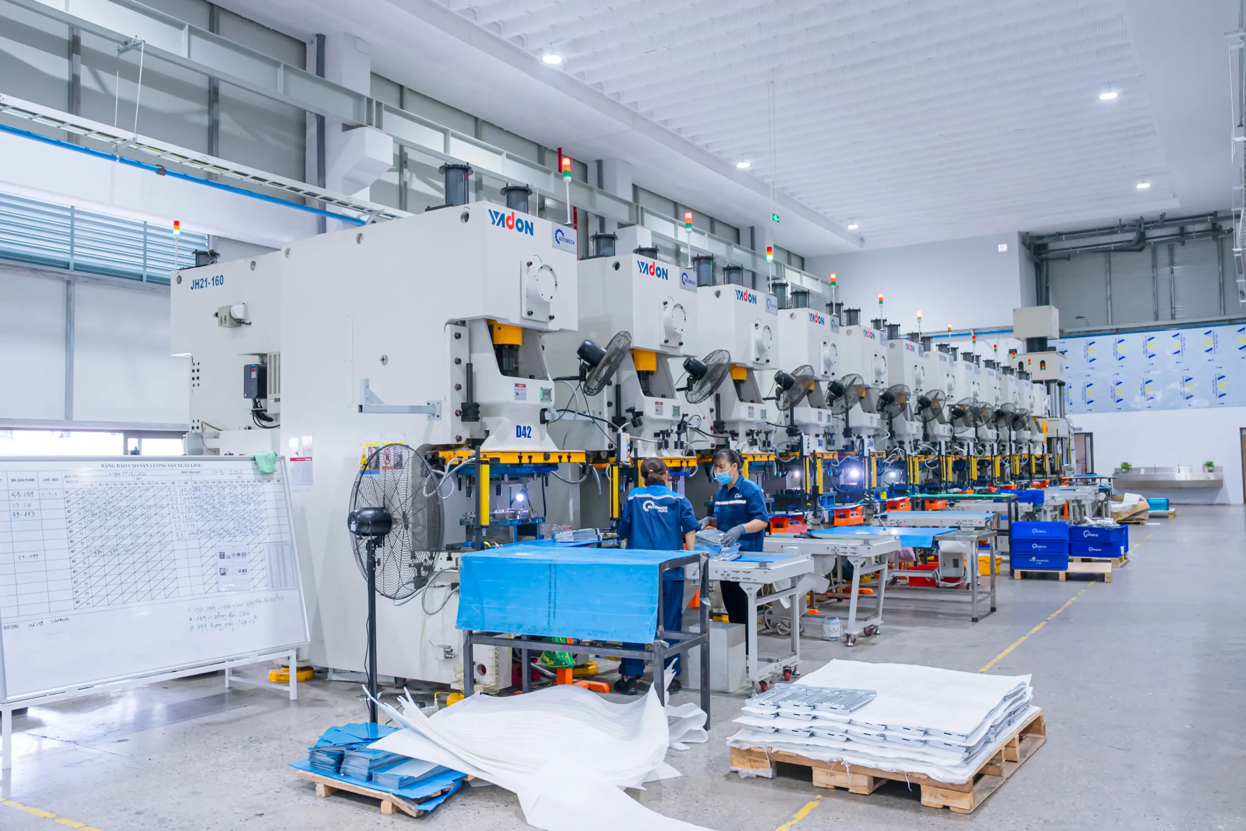
High-Precision Progressive Stamping Line Powered by Yadon Mechanical Presses
12.2 Automotive B-Pillar Manufacturing Inquiry
Looking for a reliable automotive stamping, B-pillar, or Cross Car Beam manufacturer? Send your project specifications directly to the Automech engineering team:
12.2.1 Submit technical drawings and specifications
Share 3D CAD files (STEP, IGES, CATIA) and 2D engineering drawings featuring GD&T callouts and material specifications.
12.2.2 Request manufacturing feasibility review
Our tool design and manufacturing engineers will evaluate your part geometry for stamping drawability, springback risks, and weld joint accessibility.
12.2.3 Request DFM review
Receive detailed Design for Manufacturability (DFM) feedback to optimize part geometry, reduce material scrap, and lower overall tooling costs.
12.2.4 Request automotive component quotation
Get a comprehensive quote covering production tooling, welding assembly fixtures, PPAP documentation, per-piece unit costs, and estimated lead times.
12.3 Frequently Asked Questions About B-Pillars
12.3.1 What is the B-pillar of a car?
The B-pillar of a car is the central vertical roof support post located between a vehicle’s front and rear side door openings. It connects the floor pan and rocker panel assembly to the roof frame structure.
12.3.2 Where is the B-pillar located on a car?
It is positioned along the side profile of the vehicle, directly behind the front door and in front of the rear side door or rear quarter panel.
12.3.3 What does the B-pillar do on a car?
The B-pillar supports the roof, maintains body torsional rigidity, anchors front seatbelts and door latches, and absorbs lateral collision energy to protect passengers during side impacts and rollovers.
12.3.4 What is the difference between the A-pillar, B-pillar, and C-pillar?
- A-Pillar: Located on either side of the front windshield; supports the windshield and front roof frame.
- B-Pillar: Centrally located between front and rear doors; protects the cabin during side impacts and supports the roof frame.
- C-Pillar: Located behind the rear doors; frames the rear window and reinforces the rear roof structure.
12.3.5 What material is used for a B-pillar?
Modern automotive B-pillars are manufactured using Advanced High-Strength Steels (AHSS) such as Dual-Phase (DP) steel, or Ultra High-Strength Steels (UHSS) and Press-Hardened Boron Steel (PHS) achieving tensile strengths up to 1500MPa-2000MPa.
12.3.6 How is an automotive B-pillar manufactured?
B-pillars are produced by cold stamping or hot stamping (press hardening) steel sheets into inner, outer, and reinforcement profiles. These stamped components are then joined using robotic spot welding, MIG welding, laser seam welding, or structural adhesives.
12.3.7 Why is the B-pillar important for vehicle safety?
The B-pillar forms the primary structural shield against side impacts and vehicle rollovers. It resists cabin intrusion during collisions, allowing side airbags and seatbelts to protect occupants effectively.
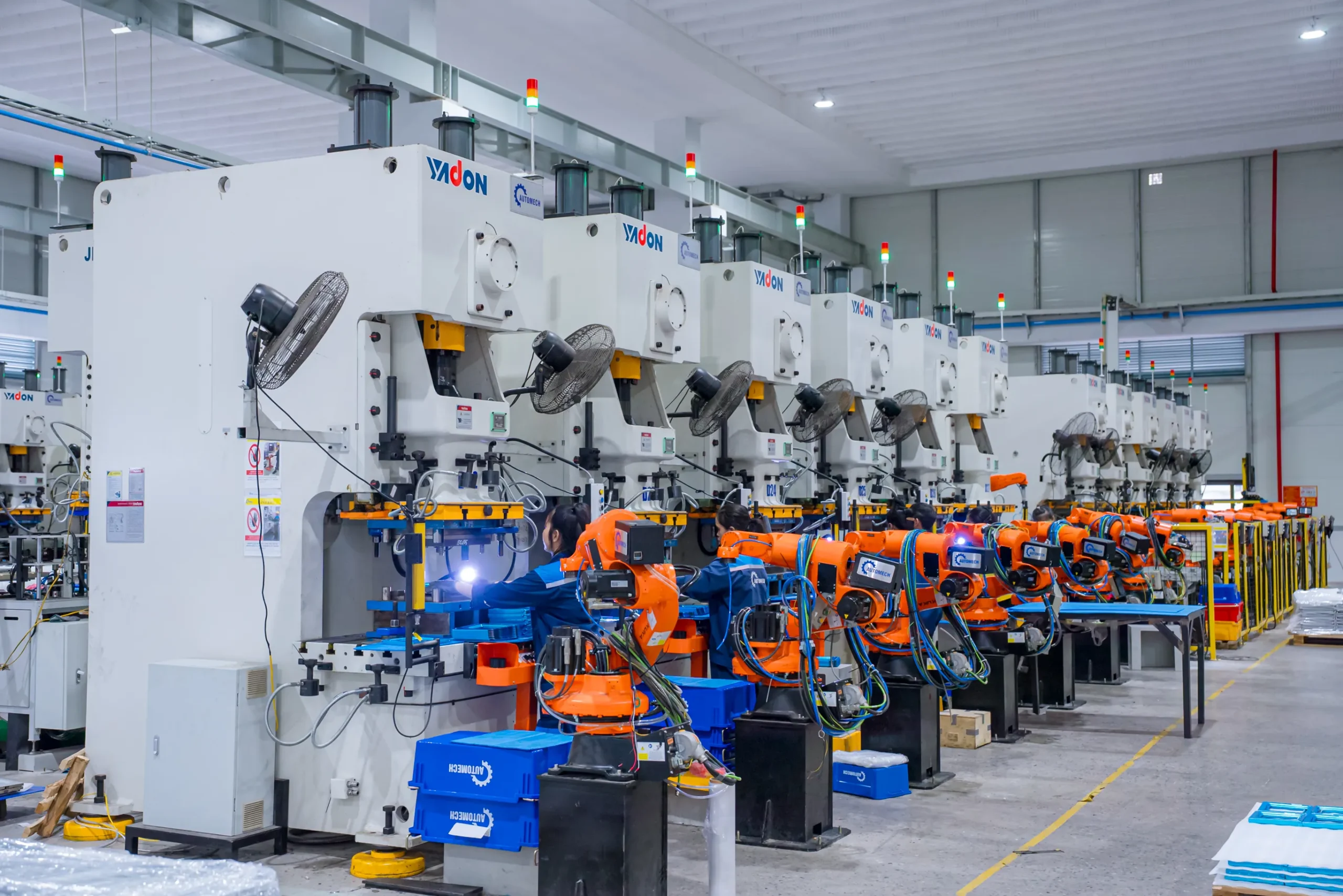
Automated Stamping Line Integrated with Industrial Robotic Loaders
12.4 Related Automotive Body Structure Topics
12.4.1 Cross Car Beam
The structural beam spanning beneath the dashboard to support steering systems, HVAC modules, and instrument panels while stiffening the front cabin against side loads.
12.4.2 Cross Car Beam supplier
Tier 1/Tier 2 manufacturing suppliers that specialize in producing precision tubular and stamped Cross Car Beam assemblies for vehicle OEMs.
12.4.3 Cross Car Beam manufacturer
A certified automotive contract manufacturing facility equipped with tube bending, stamping, and robotic welding infrastructure to produce CCB structures.
12.4.4 Cross Car Beam stamping
Precision metal stamping operations used to form mounting brackets, steering column supports, and attachment interfaces for CCB systems.
12.4.5 Cross Car Beam welding assembly
Automated robotic spot and MIG welding processes that integrate steel tubes, stamped brackets, and mounting plates into complete Cross Car Beam structures.
12.4.6 BIW automotive manufacturer Vietnam
Vietnam-based contract manufacturing factories specializing in Body-in-White (BIW) press stamping, robotic welding, and structural chassis sub-assemblies.
12.4.7 BIW welding assembly supplier
A specialized manufacturing partner providing fully automated robotic spot welding, laser joining, and assembly of complex vehicle body structural frames.
Automech Mechanical Equipment and Solutions Joint Stock Company
Head Office: No. 285 Phuc Loi Street, Phuc Loi Ward, Hanoi City
Da Nang Branch: No. 20 Nguyen Sinh Sac Street, Hoa Khanh Ward, Da Nang City
Ho Chi Minh Branch: No. 84, Street No. 10, Van Phuc Urban Area, Hiep Binh Ward, Ho Chi Minh City
Factory No. 1: Automech Automation Equipment, Mold & Tool Manufacturing Factory – Automech Demo Center: Dinh Tram Industrial Park, Nenh Ward, Bac Ninh City, Vietnam
Factory No. 2: Automech Parts Manufacturing & Component Fabrication Factory: Viet Nhat Industrial Cluster, Xuan Cam Commune, Bac Ninh City, Vietnam
Hotline: 0902 997 331
Website: https://automechmfg.com/
Fanpage: https://www.facebook.com/automech.mfg/
YouTube: https://www.youtube.com/@Automechmfg