In modern automotive structural architecture, the cross member frame serves as a vital load-bearing bridge within the vehicle body-in-white (BIW) and chassis assembly. Engineered to absorb high impact loads, resist severe torsional twisting, and maintain precise vehicle geometry under harsh operating conditions, high-quality cross member assemblies are paramount to passenger safety and dynamic performance. This detailed engineering guide provides a comprehensive analysis of cross member frame design, advanced metal stamping and robotic welding manufacturing, high-strength material selection, rigid quality control standards, and strategic OEM sourcing advantages from Vietnam.
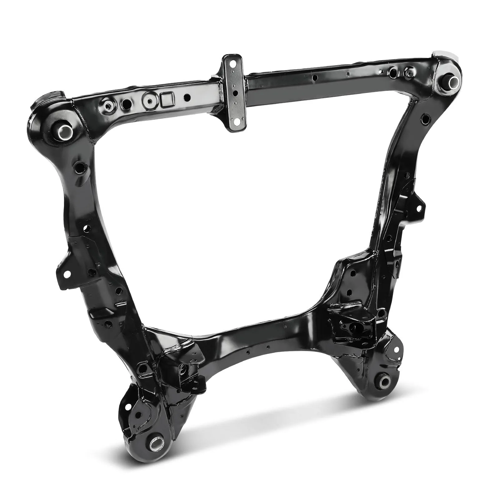
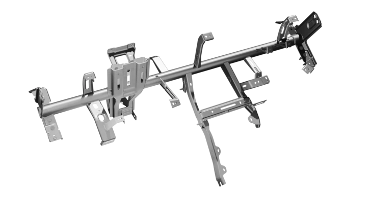
Precision-manufactured automotive subframe with a durable black e-coating, featuring complex stamping geometries and mounting points.
1. Cross Member Frame: Precision Automotive Chassis Components for OEM Manufacturing
1.1 What Is a Cross Member Frame?
1.1.1 Definition of a Cross Member Frame
A cross member frame is a key structural steel or aluminum component that runs transversely (side-to-side) across a vehicle’s chassis or unibody structure. It connects and reinforces parallel longitudinal frame rails, providing critical lateral strength, structural stiffness, and secure mounting points for essential powertrain, suspension, and body sub-assemblies.
1.1.2 Functions of a Cross Member in Automotive Chassis
The primary structural function of a cross member is to act as a rigid structural brace. It secures the vehicle chassis against lateral forces, supports heavy powerplants and transmission systems, anchors front and rear suspension control arms, and distributes dynamic road loads evenly across the vehicle frame.
1.1.3 Why Cross Members Are Critical for Vehicle Structural Integrity
Without properly engineered cross members, a chassis would suffer from excessive torsional flexing and parallelogramming under cornering and rough terrain forces. Cross members preserve cabin structural geometry, maintain wheel alignment, isolate noise and vibration, and absorb crash impact energy to safeguard occupant safety zones.
1.1.4 Cross Member vs Cross Car Beam vs Frame Rail
While often confused, these structural parts serve distinct roles:
- Cross Member Frame: Transverse chassis/underbody structural component supporting engine, suspension, battery pack, and driveline.
- Cross Car Beam (CCB): Interior structural beam mounted behind the dashboard (IP assembly) supporting steering column, airbags, and HVAC system.
- Frame Rail: Longitudinal structural members running lengthwise (front-to-back) along the vehicle underbody.
1.1.5 Common Applications Across Passenger Cars, Commercial Vehicles and EV Platforms
Cross members are universally integrated across automotive platforms: from unibody sedans and crossovers (where subframes carry suspension loads) to body-on-frame pickup trucks and heavy commercial vehicles, as well as specialized structural trays for Electric Vehicle (EV) battery packs.
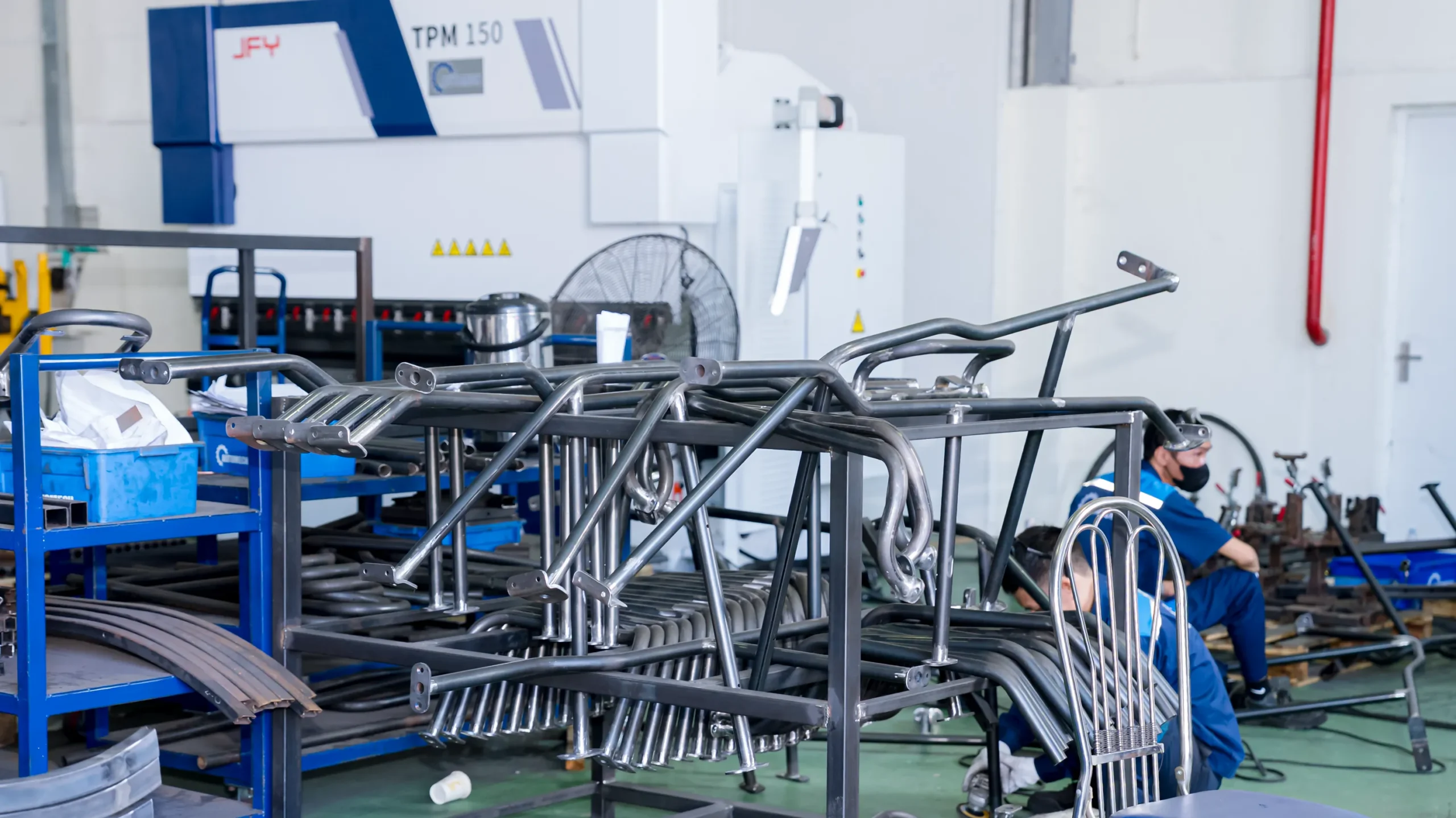
Stacked raw steel tubular subframes in the workshop prior to final surface treatment.
1.2 Types of Automotive Cross Member Frames
1.2.1 Front Cross Member
Positioned at the forward-most section of the chassis, the front cross member ties the front frame rails together, supports the radiator module, front bumper reinforcement, and provides vital front crash protection.
1.2.2 Rear Cross Member
Located at the vehicle rear, this structural component reinforces the rear axle or suspension subframe, anchors fuel tanks or rear drive units, and absorbs rear impact energy.
1.2.3 Suspension Cross Member
Also known as a subframe, this high-precision structural unit provides rigid mounting hardpoints for upper/lower control arms, steering racks, and sway bars, directly influencing vehicle handling dynamics.
1.2.4 Engine Cross Member
Specifically engineered to support the engine and transmission weight via elastomeric or hydraulic engine mounts, dampening power unit vibrations before they transfer into the passenger cabin.
1.2.5 Battery Pack Cross Members for Electric Vehicles
Integrated within EV skateboard chassis designs, these structural cross members protect delicate battery cells against lateral impact intrusion, provide structural rigidity to the battery tray, and assist in thermal management.
1.2.6 Body-in-White (BIW) Structural Cross Members
Welded into the floor pan and body-in-white structure, floor cross members prevent side-impact intrusion and reinforce seat mounting structures.
2. Cross Member Frame Manufacturing Process
2.1 Engineering & Product Development
2.1.1 OEM Drawing Review
The production process begins with a meticulous review of OEM 2D and 3D CAD models, checking technical specifications, material designations, and functional requirements.
2.1.2 CAD/CAM Engineering
Engineering teams utilize advanced CAD/CAM software (Unigraphics NX, CATIA) to model tooling geometries, blank layouts, and robotic stamping/welding sequences.
2.1.3 DFM (Design for Manufacturability)
DFM analyses optimize corner radii, draw depths, and hole distributions to avoid material tearing, thinning, or excessive wrinkling during heavy stamping operations.
2.1.4 GD&T Requirements
Establishing strict Geometric Dimensioning and Tolerancing (GD&T) ensures precise positioning of critical mounting points, hole patterns, and weld surfaces.
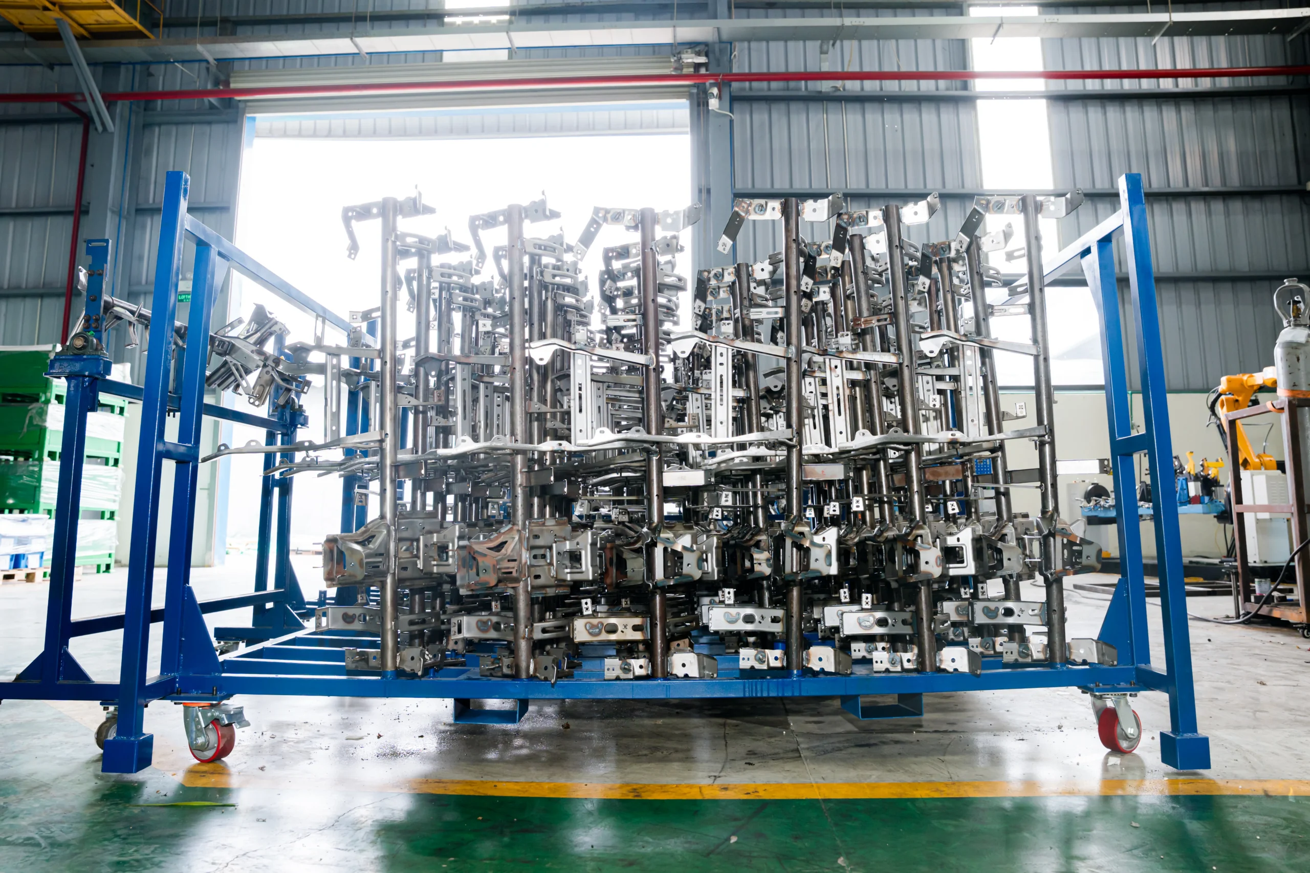
Stacked welded metal subframe components on a mobile rack ready for post-processing.
2.2 Material Selection
2.2.1 High Strength Steel (HSS)
Offers excellent yield strength and formability, ideal for standard structural chassis components requiring durable load capacity.
2.2.2 Advanced High Strength Steel (AHSS)
Grades such as Dual Phase (DP780, DP980) and Complex Phase (CP) steel provide extreme yield strengths, allowing for thinner wall gauges without sacrificing structural crashworthiness.
2.2.3 Structural Aluminum Alloys
6xxx and 7xxx series aluminum pressings and extrusions offer lightweighting benefits, essential for EV range optimization and high-end passenger vehicle subframes.
2.2.4 Material Thickness Selection
Ranging typically from 1.5mm up to 6.0mm depending on heavy-duty commercial vs. light passenger car load requirements.
2.3 Cross Member Stamping Process
2.3.1 Coil Feeding
Automated uncoiling, leveling, and servo-roll feeding systems deliver high-tensile steel strip into heavy-tonnage press lines.
2.3.2 Progressive Die Stamping
Ideal for high-volume, medium-sized cross member reinforcement bracketry and structural gussets through continuous multi-station forming.
2.3.3 Transfer Die Stamping
Utilized for deep-drawn, complex, large-format main cross member channels where mechanical transfer arms move blanks between discrete press stations.
2.3.4 Forming, Piercing and Trimming
Precision hydraulic and mechanical presses execute multi-stage deep drawing, flange bending, edge trimming, and high-accuracy hole punching.
2.3.5 Springback Compensation
Finite Element Analysis (FEA) stamping simulations (AutoForm) guide die geometry modifications to counteract elastic springback inherent in AHSS materials.
2.4 Cross Member Welding Assembly
2.4.1 Robotic Spot Welding
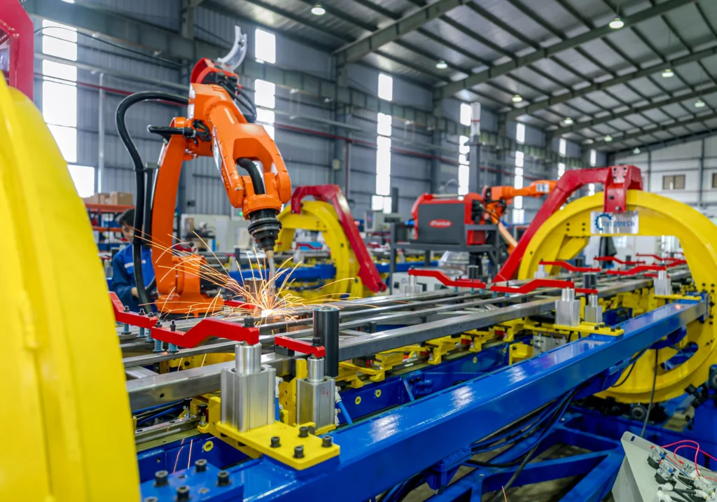
High-precision multi-axis industrial robots perform Resistance Spot Welding (RSW) to join stamped inner and outer cross member pressings with consistent heat input and joint strength.
2.4.2 MIG Welding
GMAW/MIG pulse arc welding is utilized for heavy structural seam welds on thick-gauge commercial chassis cross members and structural brackets.
2.4.3 Welding Fixtures
Custom pneumatic and hydraulic clamping fixtures securely hold stamped parts in exact alignment to prevent thermal distortion during automated welding cycles.
2.4.4 Assembly Fixtures
Poka-yoke equipped checking fixtures ensure sensor detection of all nut plates, studs, and internal sleeves prior to final assembly release.
2.4.5 Automated Assembly Lines
Fully automated robot cells integrate stamping transfer, welding, nut-clinching, and visual inspection for high repeatability and short cycle times.
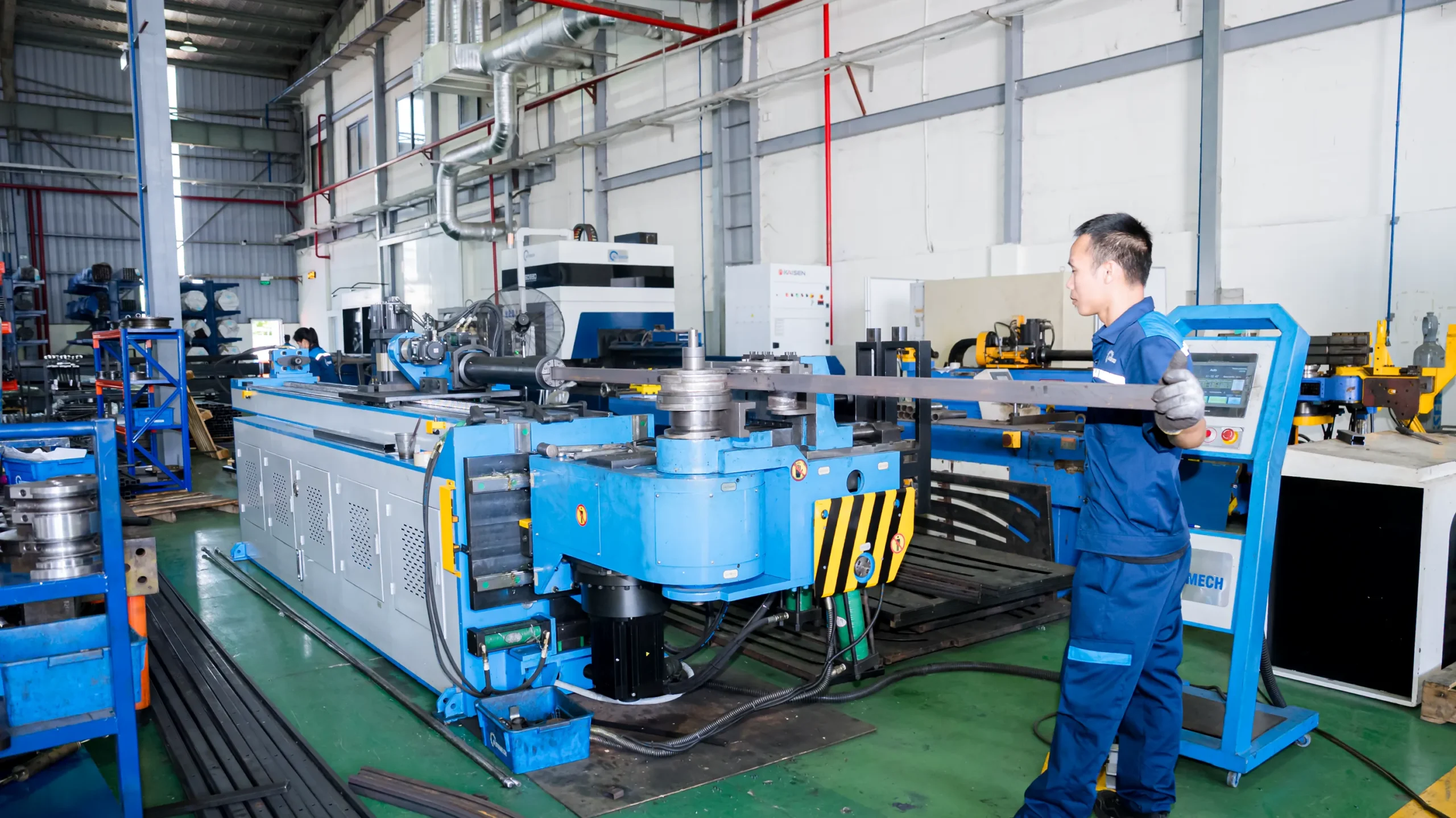
CNC tube bending machine forming a steel square tube under operator supervision.
2.5 Surface Treatment
2.5.1 Deburring
Vibratory finishing or automated robotic brush deburring removes sharp metal burrs and flash from blank edges.
2.5.2 Cleaning
Multi-stage alkaline degreasing and zinc phosphate pretreatment clean oil and contaminants to prepare metal surfaces for coating adhesion.
2.5.3 E-Coating
Cathodic Electrodeposition (CED/E-coating) delivers uniform, 15-25 micron corrosion protection over complex internal cavities and weld seams, surpassing 1,000-hour salt spray resistance tests.
2.5.4 Powder Coating
Electrostatic powder application provides additional topcoat protection against impact chipping, harsh chemicals, and environmental exposure.
2.5.5 Corrosion Protection
Wax injection and corrosion-inhibiting sealers are applied inside enclosed tubular or boxed cross member profiles for long-term underbody endurance.
3. Engineering Requirements for Automotive Cross Member Frames
3.1 Structural Performance
3.1.1 Load Distribution
Efficient load paths ensure static vehicle weight and dynamic road impacts are distributed across the primary frame network without localized stress concentrations.
3.1.2 Chassis Rigidity
High torsional and bending stiffness improves dynamic vehicle handling, steering precision, and suspension tuning fidelity.
3.1.3 Crash Energy Management
Controlled deformation zones and high energy absorption capabilities prevent engine and chassis component intrusion into the cabin during frontal or lateral collisions.
3.1.4 Fatigue Resistance
Cross member assemblies undergo multi-million cycle dynamic endurance testing to guarantee zero fatigue cracking over vehicle operational lifespans exceeding 300,000 km.
3.2 NVH Performance
3.2.1 Noise Reduction
Structural damping and tuned cross member mass distribution mitigate engine combustion rumble and road rolling noise transmission.
3.2.2 Vibration Control
Isolates driveline high-frequency harmonics through strategically tuned engine and transmission mounting bush brackets.
3.2.3 Structural Resonance Optimization
Modal analysis ensures natural cross member resonant frequencies sit far outside primary suspension and powertrain operating frequency ranges.
3.3 Dimensional Accuracy Requirements
3.3.1 Tight Dimensional Tolerances
Critical mounting point distances are held within ±0.2mm to ensure flawless alignment with mating chassis frame rails and suspension arms.
3.3.2 Hole Position Accuracy
True position hole tolerances within 0.15mm are maintained via high-precision CNC laser cutting or dedicated piercing dies.
3.3.3 Flatness Control
Mating mounting surfaces must maintain strict flatness limits to prevent clamping stress or joint loosening under heavy vibration.
3.3.4 GD&T Compliance
Full compliance with ASME Y14.5 / ISO GD&T standards ensures interchangeability across global assembly plants.
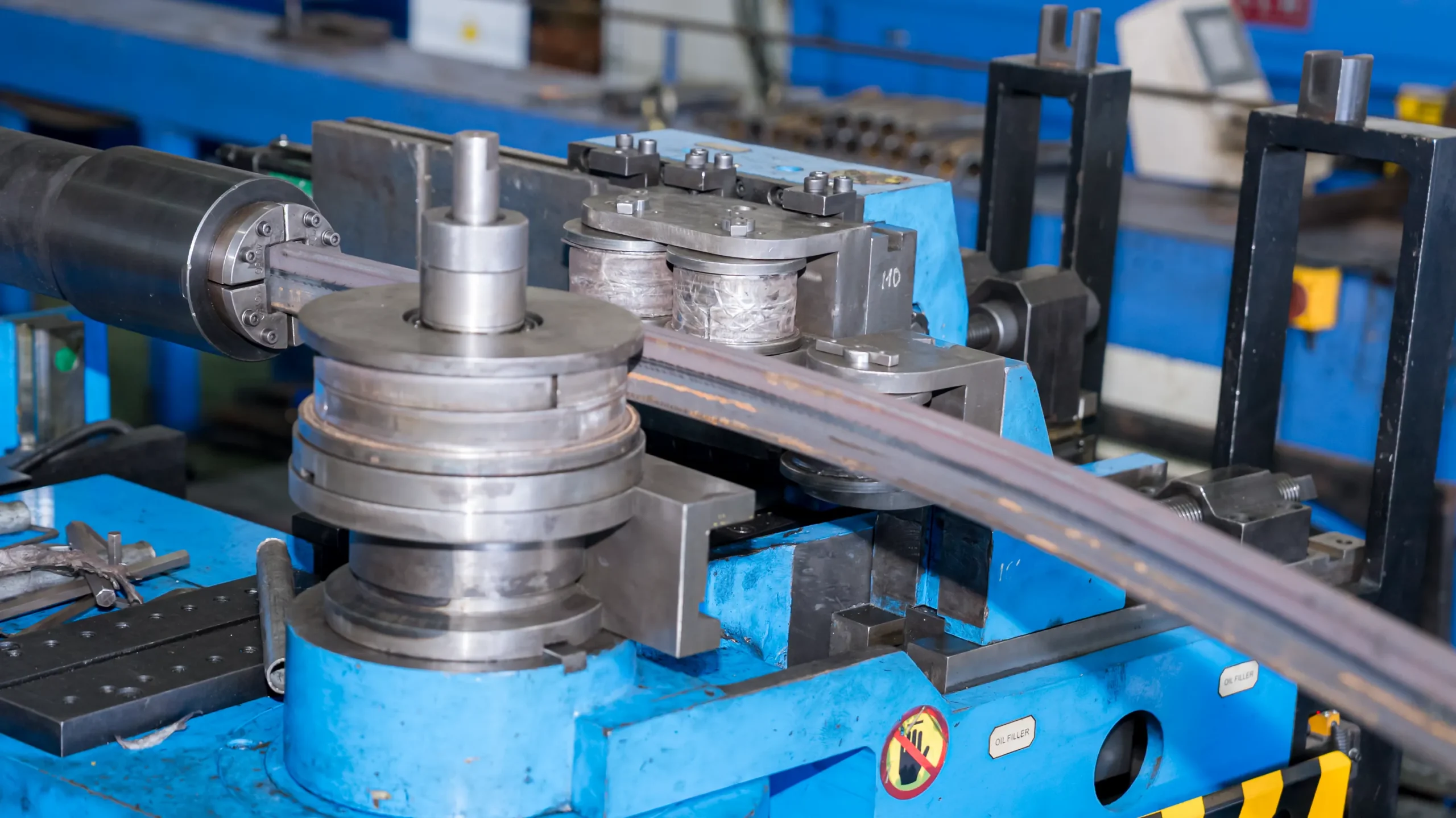
Close-up of the CNC bending dies and rollers actively shaping the metal profile.
4. Quality Control & Automotive Certifications
4.1 Inspection Systems
4.1.1 CMM Inspection
High-precision Coordinate Measuring Machines (CMM) conduct full dimensional verification against master CAD models for first-piece and periodic quality audits.
4.1.2 Laser Measurement
3D non-contact laser scanning equipment creates comprehensive surface point clouds to verify complex stampings and weldment geometries.
4.1.3 Vision Inspection
In-line optical vision systems automatically inspect every assembly for missing weld nuts, washers, or misaligned brackets.
4.1.4 First Article Inspection (FAI)
Rigorous FAI validation verifies all dimensional, metallurgical, and structural characteristics prior to production run approval.
4.2 Process Quality Control
4.2.1 In-Process SPC
Statistical Process Control tracks key product characteristics (KPCs) such as hole diameters, draw depth, and weld size in real-time.
4.2.2 Control Plan
A comprehensive Control Plan defines inspection frequencies, gauges, sampling sizes, and reaction plans at each stage of manufacturing.
4.2.3 MSA
Measurement System Analysis (Gage R&R studies) ensures all measurement devices yield repeatable and reproducible data.
4.2.4 FMEA
Failure Mode and Effects Analysis (Design & Process FMEA) proactively identifies potential failure modes to build preventative controls into tooling and assembly lines.
4.3 Automotive Quality Standards
4.3.1 ISO 9001
Foundational quality management system certification ensuring standardized business processes and operational control.
4.3.2 IATF 16949
The global automotive industry standard governing defect prevention, supply chain consistency, and continuous quality improvement.
4.3.3 PPAP
Production Part Approval Process Level 1 to 5 documentation ensures suppliers meet all OEM engineering design and specification requirements.
4.3.4 APQP
Advanced Product Quality Planning frameworks structure new program launches from concept through mass production seamlessly.
4.3.5 Full Production Traceability
Laser-etched QR codes or serial stamping provide complete traceability back to raw coil mill test reports, press operator, and robotic welding logs.
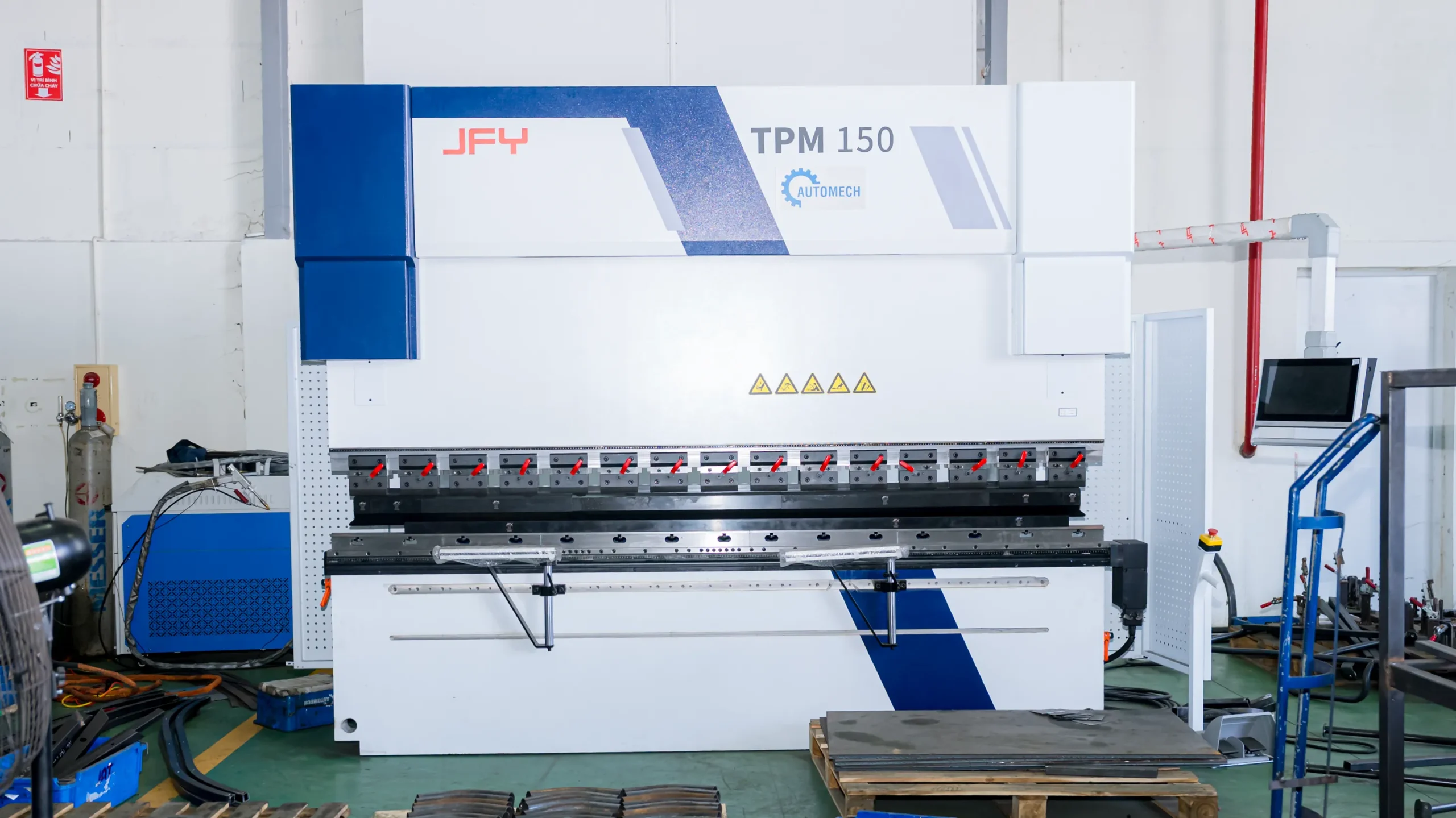
Large JFY (TPM 150) press brake machine for high-precision bending of chassis sheet metal parts.
5. Cross Member Frame Applications
5.1 Passenger Vehicles
5.1.1 Sedan Platforms
Lightweight stamped subframes supporting transverse engines and double-wishbone or MacPherson strut suspension configurations.
5.1.2 SUV Platforms
Reinforced floor and suspension cross members designed to handle higher gross vehicle weight (GVW) and off-road torsional stress.
5.1.3 Pickup Trucks
Heavy-gauge ladder-frame tubular or C-channel steel cross members offering high payload capacity and towing rigidity.
5.2 Electric Vehicles
5.2.1 Battery Pack Support Structures
High-strength floor cross members engineered to frame and protect high-voltage lithium battery enclosures during side-impact events.
5.2.2 Lightweight Chassis Components
Integrated aluminum die-cast or stamped AHSS cross members engineered to offset EV battery weight penalties.
5.2.3 Crash Safety Structures
Specially designed shear-apron and front crash subframes that absorb impact energy without compromising the passenger cell or battery pack integrity.
5.3 Commercial Vehicles
5.3.1 Truck Frames
Heavy-duty, high-tensile steel cross members riveted or bolted across main longitudinal chassis channels.
5.3.2 Bus Chassis
Full-width floor subframe structures providing torsional stability and passenger floor support across extended wheelbases.
5.3.3 Heavy-Duty Structural Components
Cast iron or extra-thick stamped steel cross members designed for extreme axle load ratings and vocational truck applications.
6. Cross Member Frame vs Other Structural Components
6.1 Cross Member vs Cross Car Beam
6.1.1 Structural Functions
Cross members handle major chassis load-bearing, suspension, and vehicle structural integrity, whereas Cross Car Beams support dash components, steering column torque, and HVAC units.
6.1.2 Installation Location
Cross members are located underbody/chassis-level; Cross Car Beams are positioned inside the upper passenger compartment behind the instrument panel.
6.1.3 Manufacturing Differences
Cross members rely on heavy stamping, high-strength welding, and cathodic E-coating; Cross Car Beams utilize hybrid steel-plastic overmolding, magnesium casting, or aluminum extrusion assemblies.
6.2 Steel vs Aluminum Cross Members
Choosing between High-Strength Steel (AHSS) and Structural Aluminum Alloys depends on the structural role, mass targets, and budget constraints of the vehicle platform.
6.2.1 Weight Comparison
Structural aluminum alloys offer a 30% to 45% weight reduction compared to traditional steel configurations. While High-Strength Steel (AHSS) allows engineers to down-gauge wall thickness to reduce weight, aluminum remains the premier choice for aggressive mass-reduction targets in high-end passenger cars and long-range Electric Vehicles.
6.2.2 Strength Comparison
Advanced High-Strength Steels (AHSS like DP780 and DP980) achieve exceptional yield strengths up to 1000+ MPa, providing superior load-bearing capacity in compact cross-sections. Structural aluminum alloys offer high tensile strength (350-450 MPa) but require larger geometric profiles to match the ultimate structural rigidity of ultra-high-strength steel.
6.2.3 Cost Comparison
Steel cross members remain highly cost-efficient due to abundant raw material availability, established stamping infrastructure, and standard robotic spot welding processes. Aluminum cross members incur higher initial material costs and require specialized joining techniques such as pulse MIG welding, self-piercing riveting (SPR), or structural bonding.
6.2.4 Typical Automotive Applications
Steel cross members are heavily utilized in mass-market passenger cars, heavy-duty pickup trucks, commercial vehicles, and load-bearing chassis frames. Aluminum cross members are predominantly used in premium vehicles, luxury performance models, and specialized structural enclosures such as EV battery pack support trays.
| Parameter | High-Strength Steel (AHSS) | Structural Aluminum Alloys |
| Weight Comparison | Baseline (Higher mass, optimized by thinner wall gauges) | 30% – 45% Lighter than conventional steel |
| Strength Comparison | Very High (Yield strengths up to 1000+ MPa) | Moderate to High (Yield strengths up to 350-450 MPa) |
| Cost Comparison | Cost-efficient material and tooling investment | Higher raw material cost and specialized welding setups |
| Typical Applications | Mass-market passenger cars, trucks, commercial vehicles | Premium vehicles, EV battery enclosures, lightweight subframes |
6.3 Progressive Die vs Transfer Die Manufacturing
Selecting the optimal stamping die configuration directly impacts tooling ROI, production line speed, and part geometry flexibility.
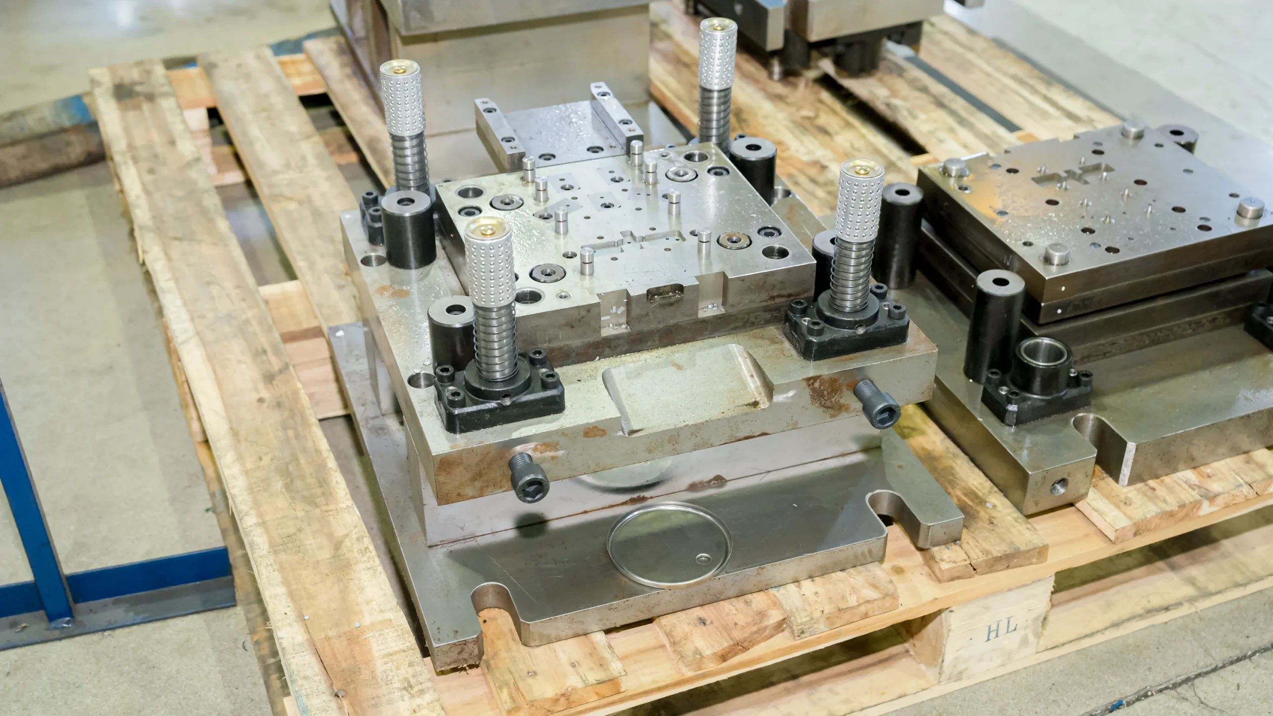
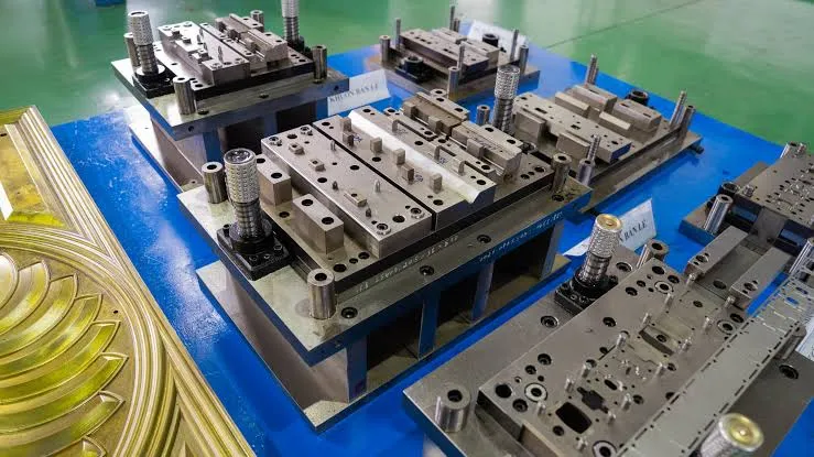
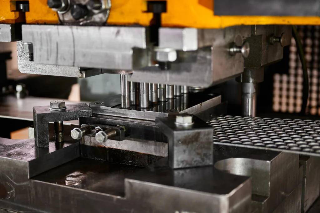
Precision metal stamping die set with complex tooling, guide pins, and springs for OEM part forming.
6.3.1 Production Volume
Progressive die stamping is designed for continuous, ultra-high-volume production (>100,000 parts/year) operating at rapid press stroke rates. Transfer die stamping is ideal for medium-to-high annual production volumes (50,000 to 150,000 parts/year) where individual blanks are physically transferred between separate press stations.
6.3.2 Tooling Investment
Progressive dies combine all forming, punching, and trimming steps into a single integrated die set, resulting in lower total tooling setup costs and footprint. Transfer die stamping requires multiple discrete dies and mechanical transfer automation arms, leading to higher initial tooling capital expenditure.
6.3.3 Component Complexity
Progressive dies excel at small-to-medium structural brackets, gussets, and reinforcement plates attached to the coil strip during forming. Transfer dies are necessary for large, deep-drawn, 3D complex main cross member channels that require full separation from the coil strip to execute severe draw steps and multi-axis flange bends.
| Factor | Progressive Die Stamping | Transfer Die Stamping |
| Production Volume | Very High (>100,000 parts/year) | Medium to High (50,000 – 150,000 parts/year) |
| Tooling Investment | Moderate to High (Single integrated die) | Higher initial tooling investment (Multiple discrete stations) |
| Component Complexity | Small-to-medium parts, moderate draw depths | Large, complex deep-drawn chassis cross members |
7. Why Global OEMs Source Cross Member Frames from Vietnam
7.1 Competitive Manufacturing Advantages
7.1.1 Cost Efficiency
Vietnam offers globally competitive manufacturing labor rates and operating overhead, delivering significant cost savings on complex metal stamping and robotic assembly programs.
7.1.2 Skilled Automotive Workforce
A rapidly growing base of highly qualified mechanical engineers, tool & die makers, and certified welding technicians ensures world-class manufacturing execution.
7.1.3 Stable Export Supply Chain
Strategically located deep-sea ports (Seaport hubs in HCMC, Hai Phong) enable efficient container shipping directly to North America, Europe, and Asia-Pacific OEM assembly facilities.
7.2 Vietnam’s Automotive Manufacturing Ecosystem
7.2.1 Automotive Stamping Suppliers
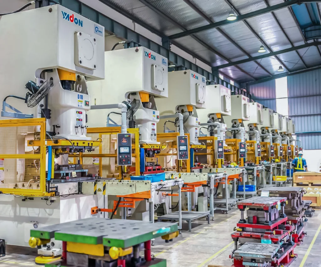
Industrial hubs in Vietnam feature modern metal stamping facilities equipped with high-tonnage mechanical and hydraulic press lines.
7.2.2 BIW Manufacturing Capabilities
Established capabilities in body-in-white sub-assembly, robotic welding, and automated metal joining processes.
7.2.3 Welding Assembly Expertise
Widespread implementation of robotic MIG and spot welding automation ensures repeatable weld quality compliant with international standards.
7.2.4 OEM Export Experience
Vietnamese suppliers possess proven track records delivering high-precision automotive components directly to top-tier international OEMs.
7.3 China+1 Sourcing Strategy
7.3.1 Supply Chain Diversification
Global automakers are actively expanding supply chain footprints into Southeast Asia to mitigate single-region concentration risks.
7.3.2 Reduced Procurement Risk
Vietnam offers a politically stable environment and favorable international trade agreements (CPTPP, EVFTA) with reduced tariff barriers.
7.3.3 Long-Term Manufacturing Partnership
Strong government support for high-tech automotive manufacturing positions Vietnam as an ideal long-term manufacturing hub for global tier-1 suppliers.
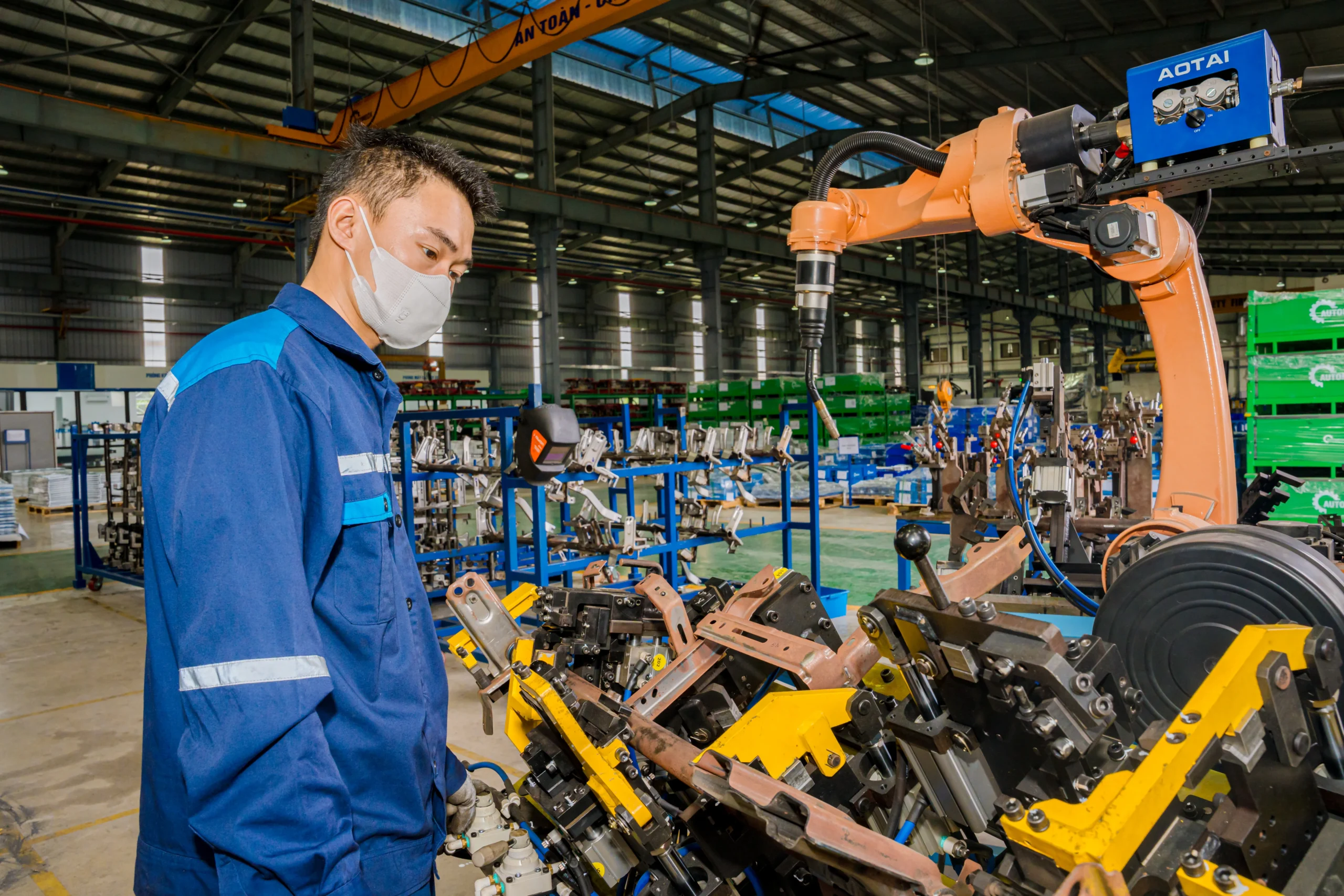
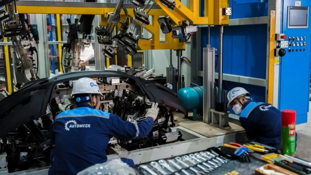
A technician monitoring an automated robotic welding cell assembling chassis subcomponents.
8. How to Choose a Cross Member Frame Supplier
8.1 Manufacturing Capabilities
8.1.1 Stamping Capacity
Verify that the supplier operates press lines up to 1000T – 2500T capable of blanking, drawing, and forming high-strength automotive steel.
8.1.2 Welding Automation
Confirm the presence of robotic spot and MIG welding cells with automated parameter monitoring to ensure weld integrity.
8.1.3 Tooling Development
Ensure in-house die design, simulation (AutoForm), machining (5-axis CNC), and tool maintenance capabilities.
8.1.4 Engineering Support
Look for robust DFM engineering teams capable of working directly with OEM CAD data to optimize tooling and production costs.
8.2 Quality Evaluation
8.2.1 Automotive Certifications
Mandatory IATF 16949 and ISO 9001 certifications demonstrating strict adherence to automotive quality management standards.
8.2.2 Inspection Equipment
In-house CMM, 3D optical laser scanners, weld destructive/non-destructive testing equipment, and salt spray corrosion test chambers.
8.2.3 Traceability System
End-to-end material and production process traceability via ERP and automated barcode systems.
8.2.4 OEM Project Experience
A proven portfolio of successfully launched automotive stamping and chassis assembly programs for Tier-1/OEM clients.
8.3 RFQ Preparation
8.3.1 Technical Drawings
Provide complete 2D drawings with GD&T specs and 3D CAD models (STEP/IGES/CATIA formats).
8.3.2 Material Specifications
Clearly define material grade standards (e.g., EN, JIS, ASTM, OEM-specific steel specifications) and thickness tolerances.
8.3.3 Annual Volume Forecast
Include annual production volume estimates, batch sizes, and overall program life cycle duration.
8.3.4 Quality Requirements
Detail all specific testing mandates (e.g., weld penetration, coating thickness, dynamic fatigue performance).
8.3.5 Packaging & Delivery Requirements
Specify returnable rack designs, anti-corrosion VCI packaging, and shipping logistics terms (FOB, CIF, DDP).
9. Why Choose Automech as Your Cross Member Frame Manufacturer in Vietnam
9.1 Automotive Manufacturing Capabilities
9.1.1 Automotive Metal Stamping
Automech operates modern metal stamping facilities equipped with heavy-tonnage presses suitable for precision automotive chassis stamping.
9.1.2 Cross Member Manufacturing
Dedicated expertise in engineering, deep-drawing, and assembling complex cross member frames for light vehicles, EVs, and commercial trucks.
9.1.3 Robotic Welding Assembly
Fully integrated multi-axis industrial robotic spot and MIG welding cells ensure uniform weld quality and high volume throughput.
9.1.4 Automotive Tooling Design
In-house tool & die engineering team delivering custom progressive and transfer dies optimized through advanced FEA stamping simulation.
9.1.5 BIW Manufacturing Support
Extensive capabilities across body-in-white stampings, floor pan sub-assemblies, and structural reinforcement components.
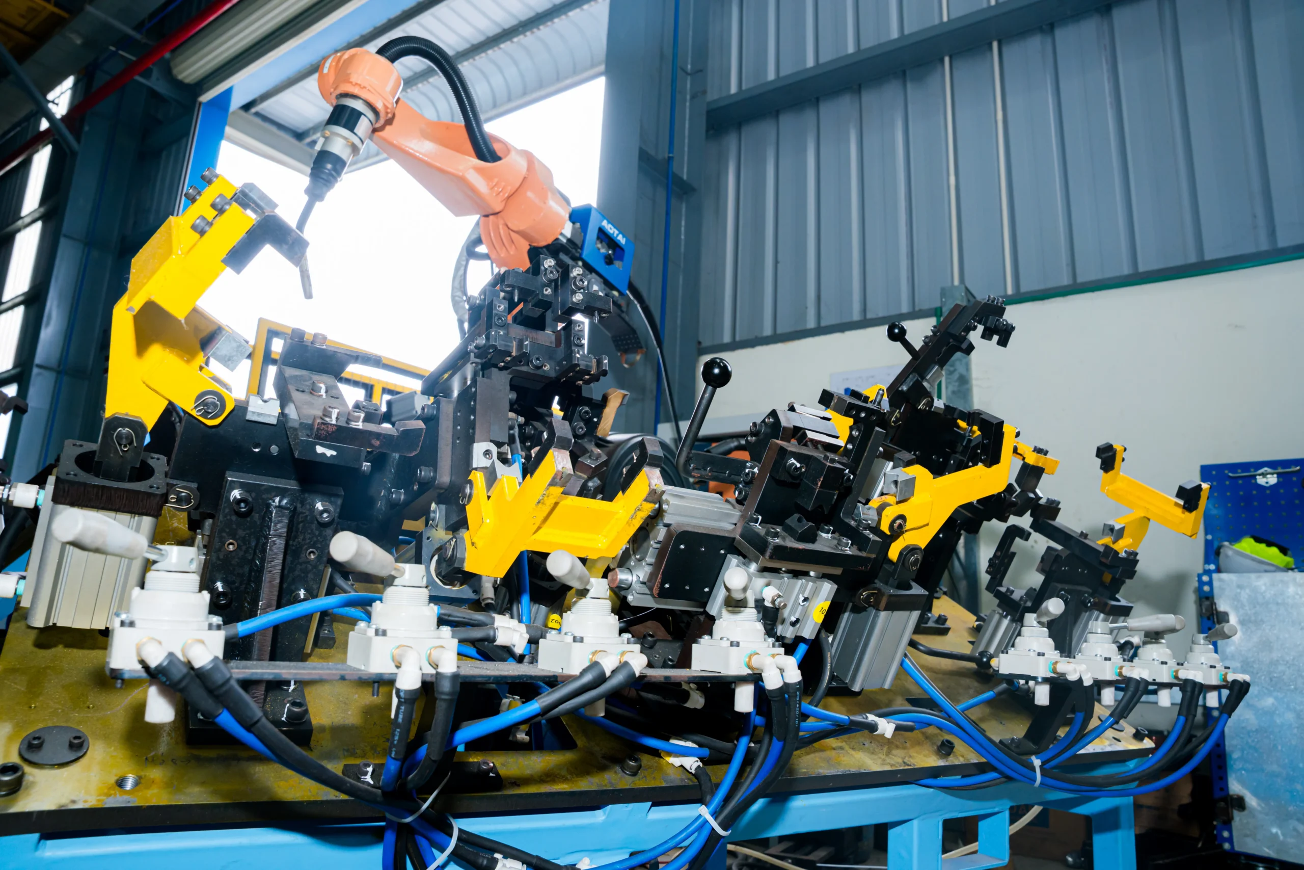
Close-up of automated pneumatic clamping fixtures with welding robot arm overhead.
9.2 Engineering & Quality
9.2.1 DFM Engineering Review
Proactive DFM analysis provided during early quote stages to optimize component design, reduce material scrap, and cut tooling lead times.
9.2.2 Prototype to Mass Production
Comprehensive support across prototype soft tooling, pre-series pilot production runs, and full-scale mass manufacturing.
9.2.3 High-Strength Steel Processing
Advanced experience working with High-Strength Steel (HSS) and Advanced High-Strength Steel (AHSS) up to DP980 grades.
9.2.4 Advanced Inspection Systems
State-of-the-art CMM room, 3D laser measurement scanning, and dedicated metallographic weld analysis labs.
9.2.5 OEM Quality Management
Full compliance with IATF 16949 standards, delivering comprehensive PPAP documentation packages (Level 1 to 5).
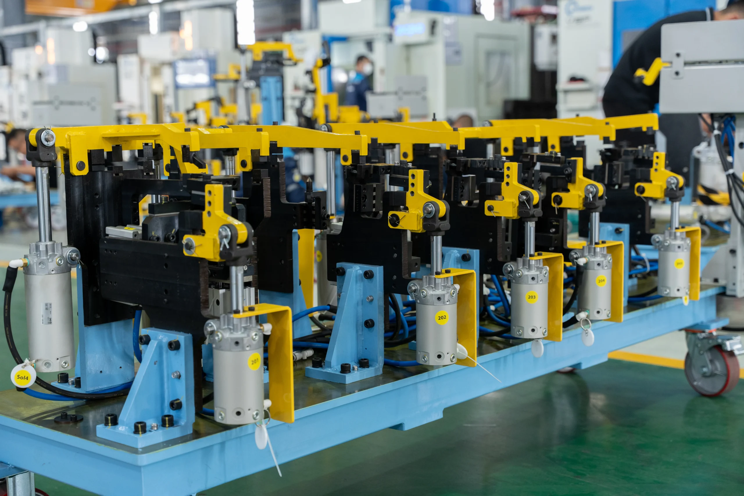
Precision pneumatic clamping fixture designed for exact alignment of parts during welding.
9.3 Global Export Support
9.3.1 Export to US & Europe
Established international export logistics experience delivering automotive components to tier-1 customers in North America, Europe, and Asia.
9.3.2 Technical Documentation
Complete engineering documentation in fluent English, including IMDS filings, material certs, and full dimensional inspection reports.
9.3.3 Dedicated Engineering Team
English-speaking project management and technical teams serving as a direct point of contact throughout program lifecycles.
9.3.4 Responsive RFQ Support
Rapid engineering review and competitive quotation turnarounds within 3 business days from receiving technical packages.
10. Featured Snippet Opportunities
10.1 Definition Snippet
10.1.1 What Is a Cross Member Frame?
A cross member frame is a key structural chassis component installed transversely across a vehicle frame. It connects longitudinal frame rails to reinforce structural stiffness, support engine, transmission, and suspension components, and absorb impact loads during collisions.
10.2 List Snippet
10.2.1 Main Functions of a Cross Member Frame
- Connects left and right longitudinal frame rails for structural integrity.
- Resists chassis torsional twisting and bending under dynamic road forces.
- Provides rigid mounting points for engine, transmission, and suspension control arms.
- Absorbs and dissipates impact energy during vehicle crashes.
- Reduces noise, vibration, and harshness (NVH) in the passenger cabin.
10.2.2 Cross Member Manufacturing Process
- Engineering & DFM Review: Tooling design and FEA stamping simulation.
- Material Blanking & Stamping: Deep drawing, piercing, and trimming via progressive or transfer dies.
- Robotic Welding Assembly: Joining sub-components via automated spot and MIG welding.
- Surface Finishing: E-coating (CED) and powder coating for 1,000+ hour corrosion protection.
- Quality Inspection: CMM measurement, weld testing, and PPAP approval.
10.2.3 Benefits of High-Strength Steel Cross Members
- High Strength-to-Weight Ratio: Enables weight reduction without compromising structural safety.
- Superior Crash Performance: Absorbs high impact energy during collisions.
- Cost-Effective Manufacturing: Highly economical for mass production compared to exotic light alloys.
- Excellent Fatigue Endurance: Withstands long-term dynamic loading without structural failure.
10.3 Comparison Table
10.3.1 Steel vs Aluminum Cross Members
Steel cross members offer maximum strength and cost efficiency for high-volume production, while aluminum alloys provide 30%-45% weight savings for EV platforms and luxury vehicles.
10.3.2 Cross Member vs Cross Car Beam
Cross members are underbody load-bearing chassis frames, whereas Cross Car Beams are interior structural beams located behind the dashboard supporting IP assemblies.
10.3.3 Progressive Die vs Transfer Die Stamping
Progressive dies are designed for continuous high-speed stamping of small-to-medium parts, whereas transfer dies handle large, deep-drawn main cross member components.
10.4 Checklist Snippet
10.4.1 How to Choose a Cross Member Frame Supplier
- Holds active IATF 16949 and ISO 9001 quality certifications.
- Equipped with 1000T+ stamping press capacity for automotive gauges.
- Features robotic spot and MIG welding automation capabilities.
- Has in-house CMM, 3D laser scanning, and weld analysis equipment.
- Provides complete PPAP (Level 1-5) and IMDS documentation.
- Demonstrates proven experience exporting to global OEM/Tier-1 markets.
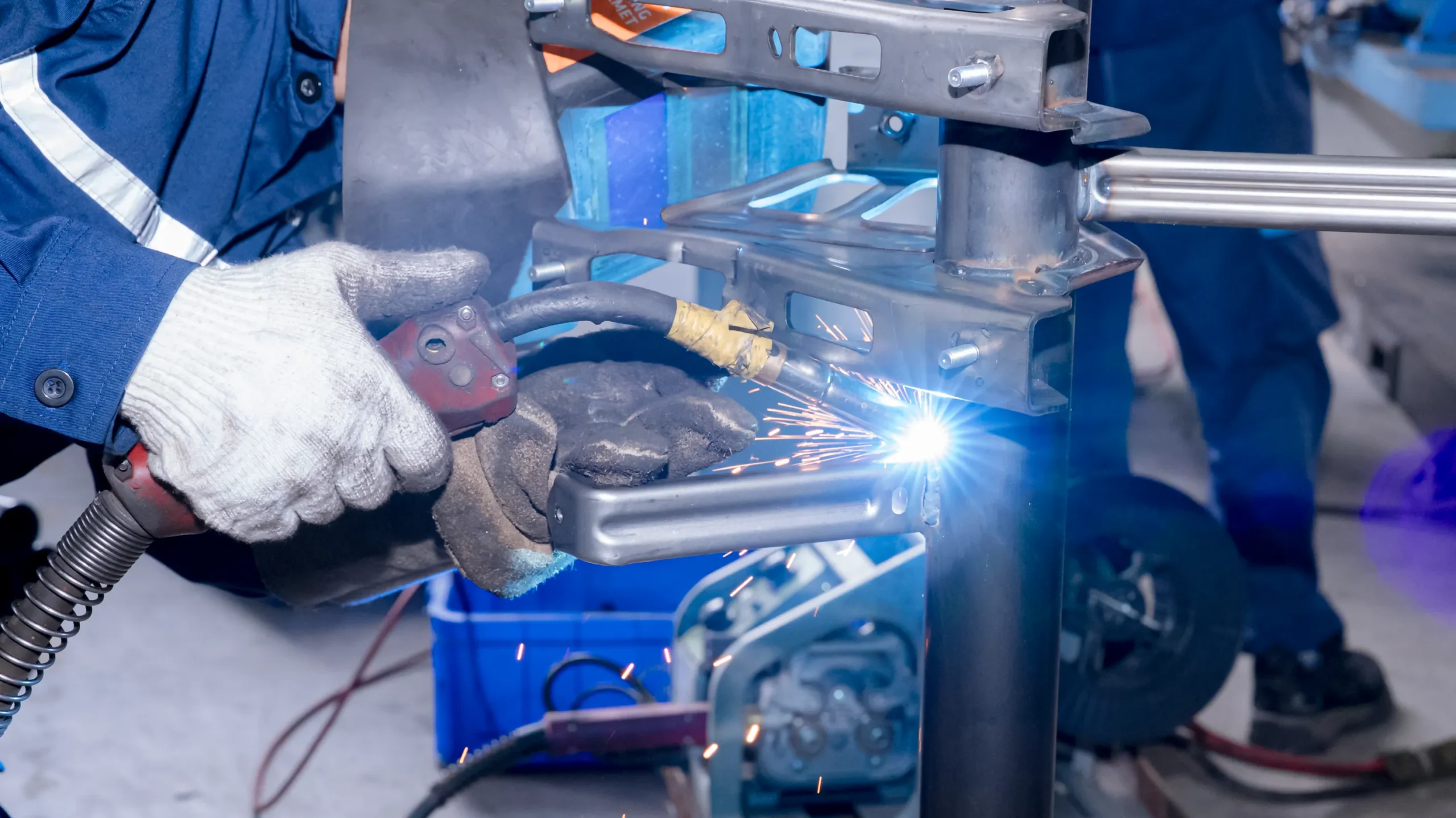
Welder executing precise MIG/GMAW welding on structural steel cross member joint.
11. People Also Ask (PAA)
11.1 What is a cross member frame in automotive engineering?
A cross member frame is a transverse structural steel or aluminum beam that spans across a vehicle chassis. It connects the main frame rails, provides essential mounting points for the powertrain and suspension, and increases overall chassis torsional rigidity.
11.2 What does a cross member do in a vehicle chassis?
A cross member supports critical vehicle sub-assemblies (engine, transmission, suspension), maintains frame alignment, absorbs road shock and vibration, and distributes crash impact loads safely across the chassis structure.
11.3 What materials are commonly used for cross member frames?
Cross members are typically manufactured from High-Strength Steel (HSS), Advanced High-Strength Steel (AHSS like DP780/DP980), and structural aluminum alloys (6xxx/7xxx series) for weight-sensitive applications such as Electric Vehicles.
11.4 How are automotive cross member frames manufactured?
They are produced through multi-stage manufacturing: coil feeding, progressive or transfer die metal stamping, automated robotic spot/MIG welding, cathodic electrodeposition (E-coating) for anti-corrosion, and 100% quality inspection using CMM and laser scanning.
11.5 Why are high-strength steel cross members preferred?
High-strength steel offers an exceptional balance of mechanical strength, crash energy absorption, fatigue resistance, and mass production cost-efficiency compared to conventional mild steels or expensive lightweight composites.
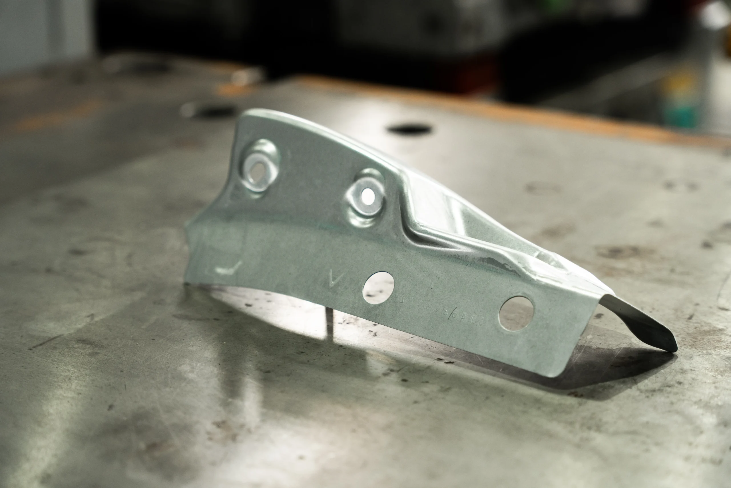
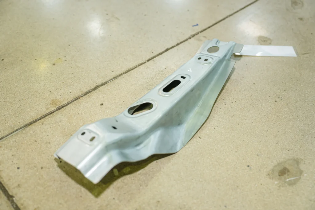
Stamped and formed high-strength steel reinforcement bracket with mounting holes.
11.6 How do I choose a reliable cross member frame supplier?
Select a supplier with IATF 16949 certification, heavy-tonnage stamping presses, robotic welding automation, in-house CMM quality verification, full PPAP capabilities, and proven automotive export experience.
11.7 Why should OEMs source cross member frames from Vietnam?
Sourcing from Vietnam provides significant cost advantages, a skilled engineering workforce, strategic sea port connectivity, and strong supply chain diversification benefits under a ‘China+1’ strategy.
12. Frequently Asked Questions (FAQ)
12.1 Can you manufacture cross member frames based on OEM drawings?
Yes. Automech manufactures cross member frames strictly according to customer 2D technical drawings, 3D CAD models, and material specifications, providing complete DFM feedback prior to tooling build.
12.2 What production volumes can Automech support?
We support prototype sampling, low-volume pre-series runs, and full mass production scaled up to 500,000+ units annually.
12.3 Which materials can be processed?
We process low-carbon steel, High-Strength Steel (HSS), Advanced High-Strength Steel (AHSS – DP600, DP780, DP980), stainless steel, and structural aluminum alloys.
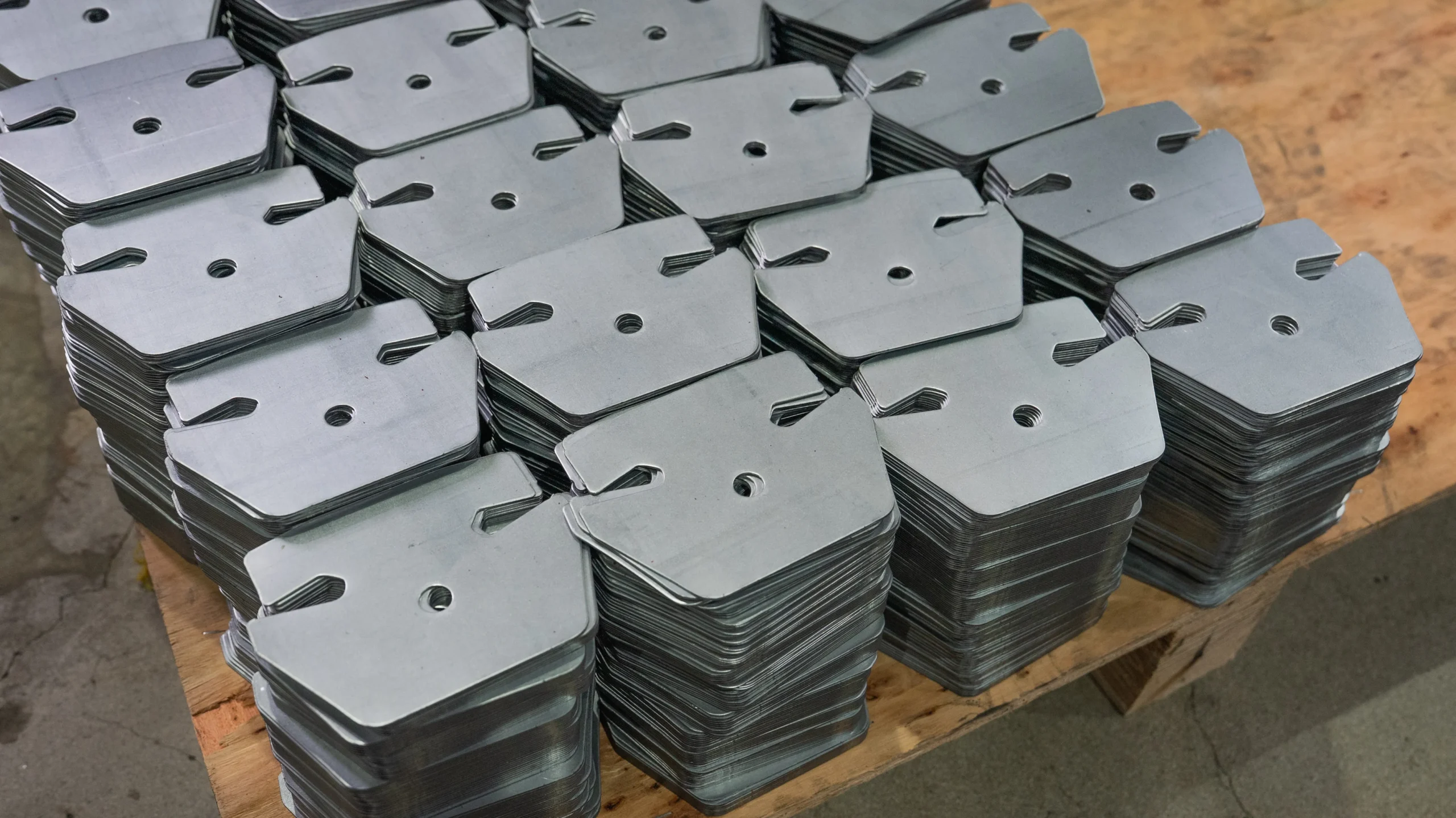
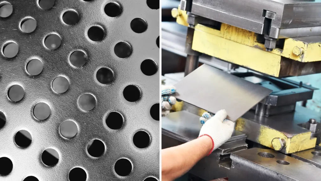
Neat stacks of stamped metal sheet blanks with pierced holes, ready for forming.
12.4 Do you provide tooling design and manufacturing?
Yes. Automech provides end-to-end tooling design, FEA stamping simulation, CNC tooling manufacture, and life-of-program die maintenance.
12.5 What automotive quality standards do you follow?
Our manufacturing processes operate in strict compliance with IATF 16949 and ISO 9001 standards, providing full PPAP documentation and traceability.
12.6 Can you support the prototype, pilot, and mass production?
Yes, we provide seamless project lifecycle support from initial prototype soft tooling and pilot line testing to full automated mass production.
12.7 How can I request a quotation for cross member frame manufacturing?
You can submit your RFQ package (3D CAD, 2D drawings with GD&T, material specs, and annual volumes) directly through our website contact portal or engineering email.
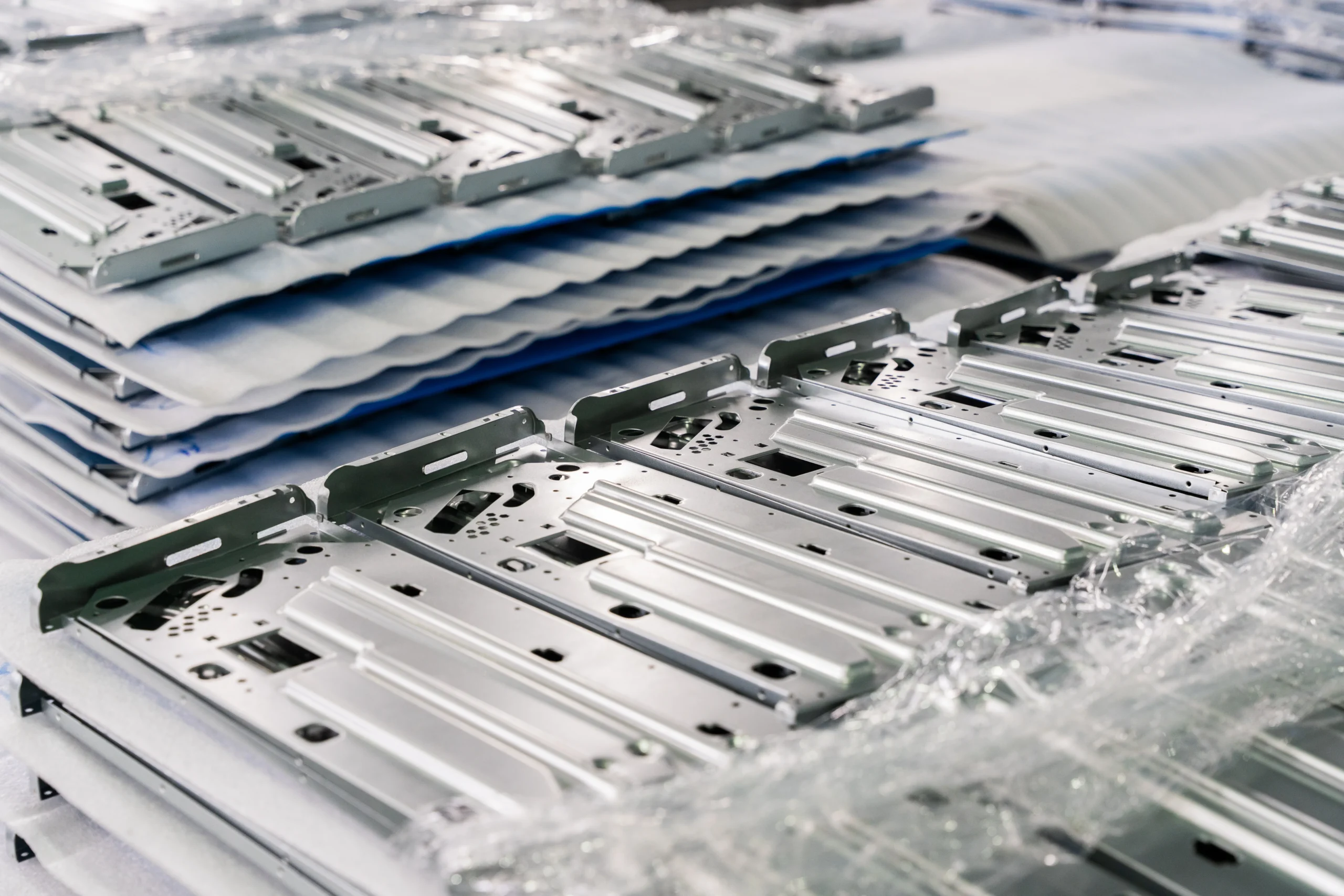
Stamped sheet metal structural parts neatly stacked and protected with VCI wrap for shipping.
13. Call to Action
Partner with Automech for OEM Cross Member Frame Manufacturing in Vietnam. Looking for a certified automotive stamping and robotic assembly partner to optimize your chassis supply chain? Contact our engineering team today.
13.1 Request a Cross Member Frame RFQ
Get a detailed cost proposal tailored to your annual volume forecasts, tooling budget, and delivery schedules. Our commercial engineering team provides rapid quote turnarounds.
13.2 Upload CAD Drawings & Technical Specifications
Securely submit your 3D CAD models (STEP/IGES/CATIA) and 2D GD&T technical drawings through our encrypted client portal for immediate technical evaluation.
13.3 Request DFM & Manufacturing Feasibility Review
Receive complimentary Design for Manufacturability (DFM) feedback from our senior tooling engineers to optimize part geometry, minimize material scrap, and lower stamping costs.
13.4 Contact Automech Automotive Engineering Team
Speak directly with our English-speaking project managers and chassis engineering specialists to discuss technical requirements, material specifications, and quality standards.
13.5 Get a Competitive Quote for OEM Cross Member Frame Manufacturing
Receive a comprehensive, highly competitive manufacturing quotation within 3 business days, fully backed by complete PPAP commitment and IATF 16949 quality compliance.
Automech Mechanical Equipment and Solutions Joint Stock Company
Head Office: No. 285 Phuc Loi Street, Phuc Loi Ward, Hanoi City
Da Nang Branch: No. 20 Nguyen Sinh Sac Street, Hoa Khanh Ward, Da Nang City
Ho Chi Minh Branch: No. 84, Street No. 10, Van Phuc Urban Area, Hiep Binh Ward, Ho Chi Minh City
Factory No. 1: Automech Automation Equipment, Mold & Tool Manufacturing Factory – Automech Demo Center: Dinh Tram Industrial Park, Nenh Ward, Bac Ninh City, Vietnam
Factory No. 2: Automech Parts Manufacturing & Component Fabrication Factory: Viet Nhat Industrial Cluster, Xuan Cam Commune, Bac Ninh City, Vietnam
Hotline: 0902 997 331
Website: https://automechmfg.com/
Fanpage: https://www.facebook.com/automech.mfg/
YouTube: https://www.youtube.com/@Automechmfg