In modern automotive engineering, structural car beams play a pivotal role in defining chassis torsional rigidity, crash energy dissipation, and passenger safety cell integrity. This technical guide provides a comprehensive analysis of car beam design, cross car beam (CCB) cockpit integration, metal stamping and robotic welding assembly, Advanced High-Strength Steel (AHSS) selection, IATF 16949 quality compliance, and global OEM sourcing opportunities with Automech in Vietnam.
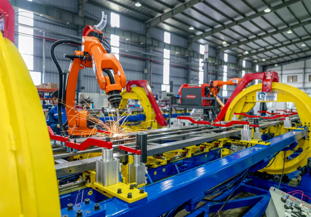
A technician operating a teach pendant to control a multi-axis robotic welding cell.
1. Car Beam: Comprehensive Guide to Automotive Structural Beams, Manufacturing Processes & OEM Sourcing
1.1 What Is a Car Beam?
1.1.1 Definition of a Car Beam in Automotive Engineering
In automotive engineering, a car beam is a load-bearing, structural metallic component engineered to provide mechanical strength, torsional rigidity, and impact energy absorption across various sections of a vehicle’s body architecture.
1.1.2 Primary Functions in Vehicle Body Structure
- Supports localized dynamic and static mechanical loads during operation.
• Acts as an anchor frame for major subsystems, including steering columns, HVAC units, dashboards, and exterior panels.
• Forms defined deformation zones that control force dissipation during collision events.
1.1.3 Importance in Crashworthiness, Rigidity, and Passenger Safety
Car beams form the core structural protection cage for occupants. High rigidity prevents structural intrusion into the cabin during impacts, while controlled crashworthiness allows the beams to absorb and disperse kinetic energy predictably, maintaining safety cell integrity under extreme stress.
1.2 Role of Car Beams in Vehicle Body Structure
1.2.1 Structural Load Distribution
Beams distribute static loads (vehicle curb weight, payload) and dynamic loads (cornering forces, braking torque, road shocks) evenly across the chassis, preventing localized stress concentrations and fatigue fractures.
1.2.2 Crash Energy Management
During frontal, side, or rear impacts, structural car beams function as primary energy absorbers. They deform in predetermined plastic deformation modes to channel impact energy away from the passenger compartment.
1.2.3 Occupant Protection
By forming a rigid structural boundary around the cabin—specifically via door intrusion beams, cross-car beams, and roof rails—they preserve survival space during rollover and collision scenarios.
1.2.4 NVH (Noise, Vibration, Harshness) Performance
High-stiffness structural beams raise the natural frequency of the vehicle chassis, mitigating sympathetic vibrations, cabin boom, and mechanical road noise transmitted into the passenger area.
1.2.5 Integration Within Body in White (BIW)
Car beams form the skeleton of the Body in White (BIW) assembly. They are joined directly to floor pans, A/B/C pillars, side frames, and engine cradles using automated joining technologies.
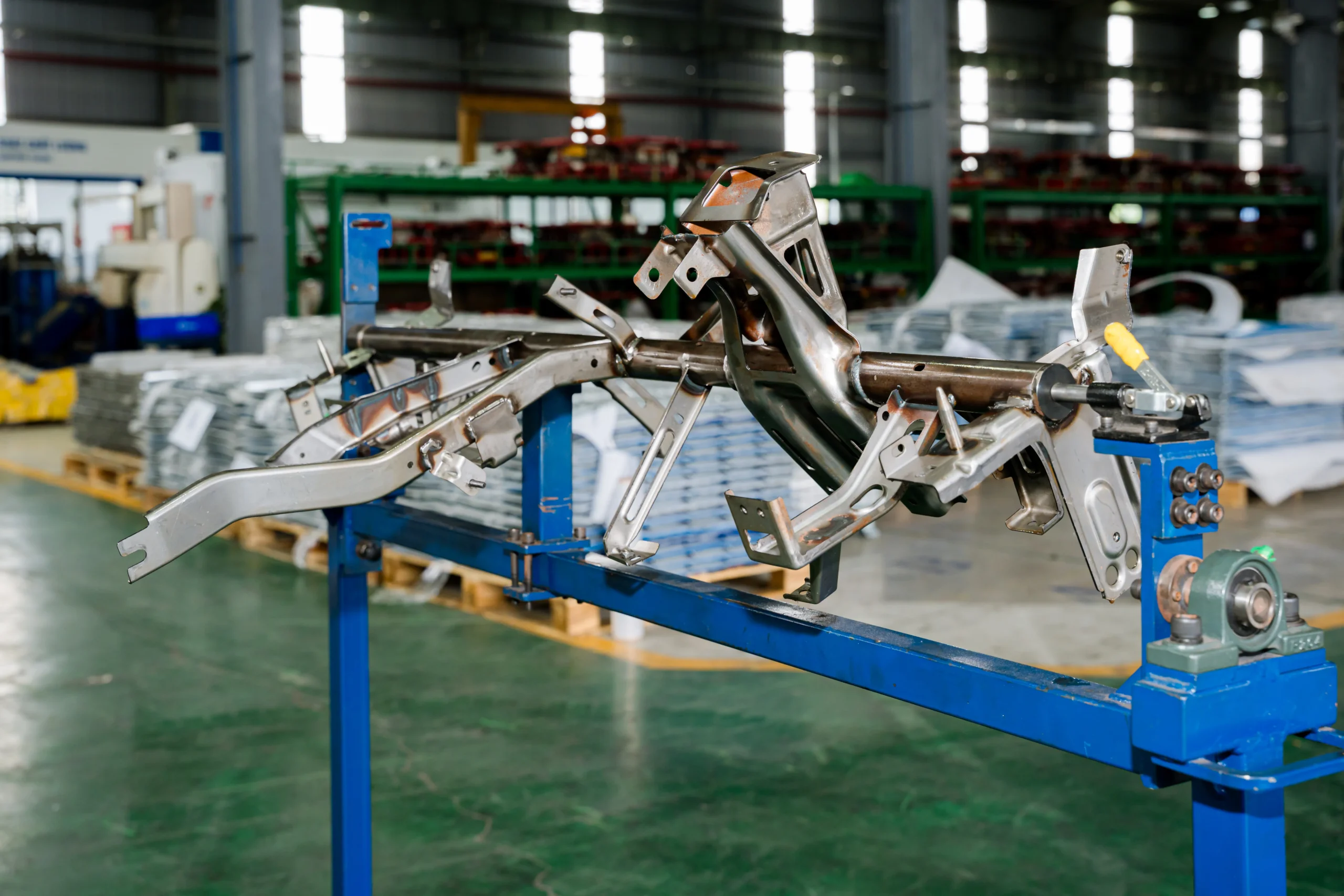
Fully assembled and welded structural chassis beam resting on a checking fixture in the factory.
2. Types of Automotive Car Beams
2.1 Cross Car Beam
2.1.1 Structure and Design
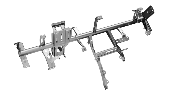
A transverse structural member extending from the left A-pillar to the right A-pillar behind the instrument panel. It usually features tubular steel, hydroformed, or die-cast aluminum configurations with complex mounting brackets.
2.1.2 Dashboard and Instrument Panel Support
Provides rigid mounting points for the steering column, passenger/driver airbag modules, infotainment system, HVAC unit, and glovebox assembly, eliminating steering wheel oscillation during idle and driving.
2.1.3 Typical Manufacturing Process
Formed via high-precision tube bending, hydroforming, or stamping, followed by robotic MIG or laser bracket welding and final CMM check.
2.2 Front Car Beam
2.2.1 Front-End Structural Reinforcement
Positioned directly behind the front bumper fascia, this beam links the left and right front longitudinal rails, reinforcing the vehicle’s front structural box.
2.2.2 Crash Load Management
Acts as the first line of defense in frontal collisions, transferring impact forces to crash boxes and longitudinal rails to absorb maximum kinetic energy before it reaches the cabin.
2.3 Rear Car Beam
2.3.1 Rear Structure Reinforcement
Mounted at the tail section of the vehicle framework, connecting the rear longitudinal members to reinforce the trunk floor and rear bumper area.
2.3.2 Safety Performance
Protects the fuel tank, high-voltage EV battery pack, and rear occupants against high-speed rear-end impact intrusions, complying with global rear-crash regulations.
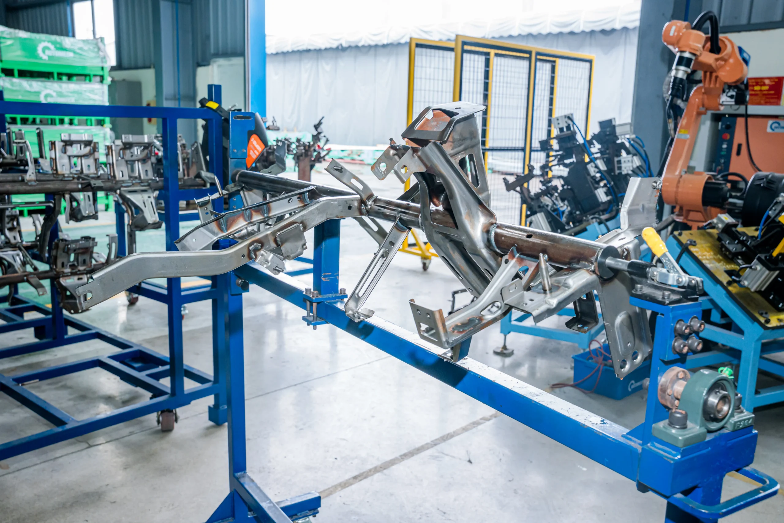
Welded Cross Car Beam subassembly mounted on a rotating fixture for multi-angle assembly and inspection.
2.4 Instrument Panel Beam
2.4.1 Cockpit Structural Support
Serves as the structural skeleton for the entire cockpit architecture, transferring side-impact loads across the vehicle width to mitigate cabin intrusion.
2.4.2 Interior Module Integration
Integrated with wire harness channels, ductwork channels, and structural brackets to enable modular ‘cockpit sub-assembly’ insertion on the main OEM assembly line.
2.5 Structural Reinforcement Beams
2.5.1 Side Reinforcement
Door intrusion beams made of Ultra-High-Strength Steel (UHSS) or press-hardened boron steel that prevent lateral intrusion during T-bone side-impact collisions.
2.5.2 Roof Reinforcement
Transverse and longitudinal roof bows linking the side roof rails to support roof crush resistance testing (e.g., IIHS roof strength standards) and protect occupants during rollovers.
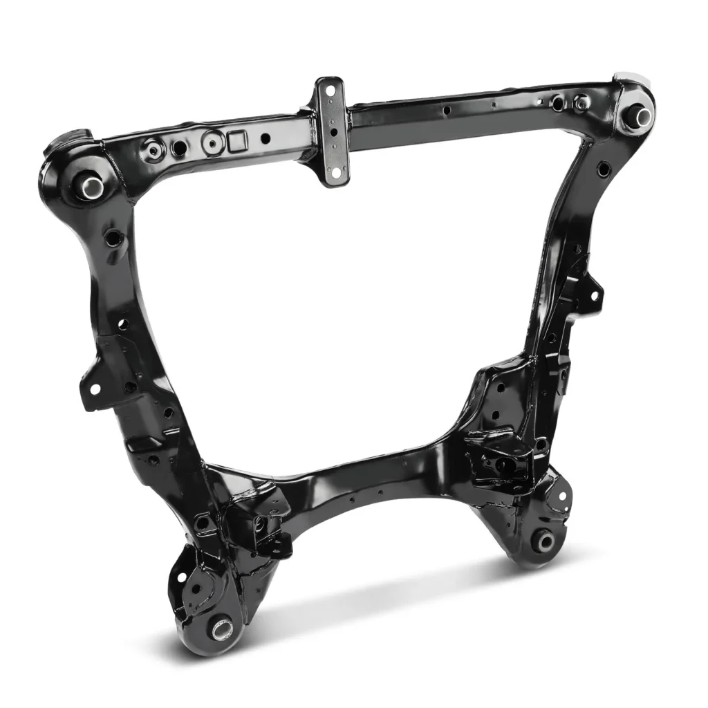
2.5.3 Chassis Structural Members
Underbody cross-members and subframe beams that carry suspension load control points, engine/drivetrain mounts, and battery tray supports for electric vehicles.
3. Car Beam Manufacturing Process
3.1 Engineering Design & DFM
3.1.1 CAD/CAE Design
3D parametric modeling (CATIA, Siemens NX) to define geometry, interface packaging, and spatial constraints within the BIW environment.
3.1.2 Structural Simulation
Finite Element Analysis (FEA) evaluating static stiffness, modal frequencies, occupant safety crashes (LS-DYNA), and fatigue life under cyclic loads.
3.1.3 Manufacturing Feasibility Review
Design for Manufacturability (DFM) checks to evaluate material stretch limits, springback effects, deep-draw feasibility, and weld torch access.
3.2 Metal Stamping Process
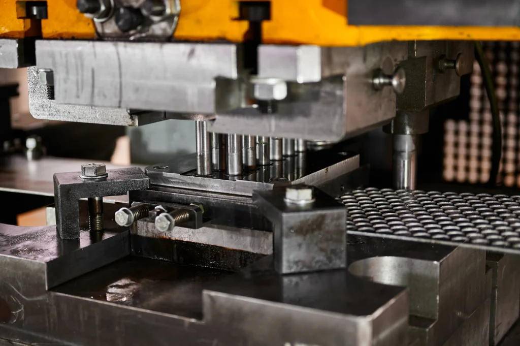
3.2.1 Progressive Die Stamping
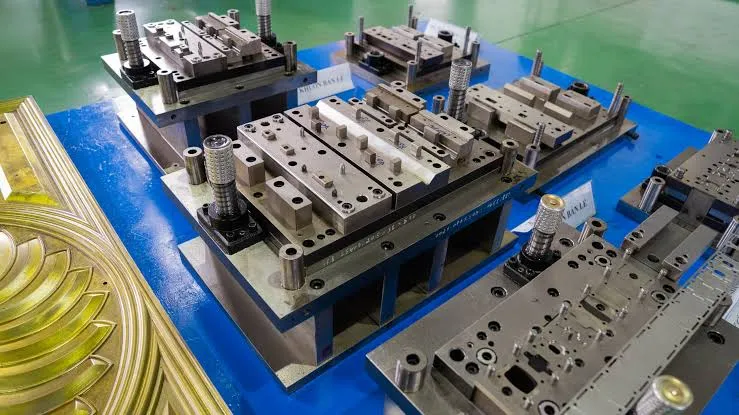
A single continuous strip feed passing through multiple sequential stations (cutting, punching, bending, forming) for high-speed, high-volume production of smaller brackets and beam components.
3.2.2 Transfer Stamping
Mechanical transfer arms shift individual sheet metal blanks between discrete stamping dies in a press line; ideal for large, complex structural beam sections.
3.2.3 High-Precision Forming
Utilizes tight-clearance die sets and hydraulic/servo press systems to maintain extremely tight tolerances on high-strength metals while controlling material thinning.
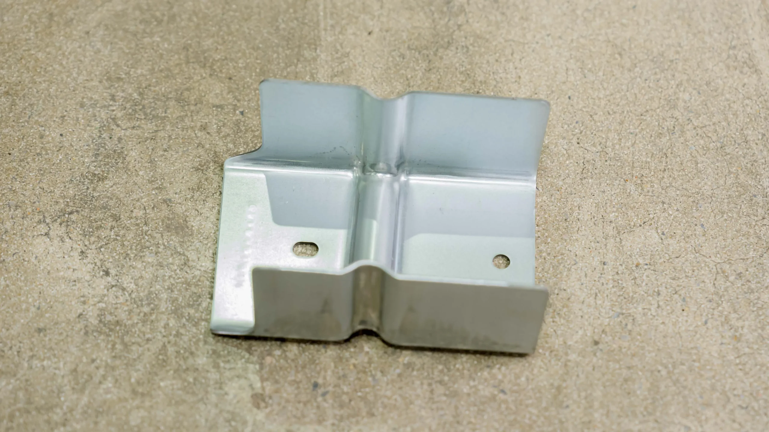
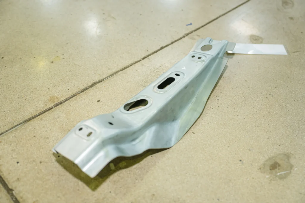
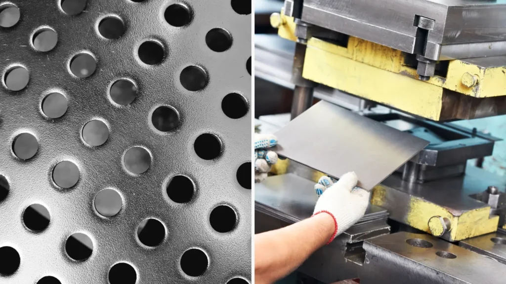
Stamped sheet metal U-channel bracket with mounting holes for structural support.
3.3 Welding Assembly
3.3.1 Robotic Spot Welding
Automated Resistance Spot Welding (RSW) using multi-axis robots to join multi-layer sheet metal assemblies with repeatable current, force, and timing controls.
3.3.2 MIG Welding
Metal Inert Gas (GMAW) welding used for continuous structural seam joints on heavy-gauge cross-car beam tubes, brackets, and aluminum structures.
3.3.3 Laser Welding
High-energy density laser joining offering narrow weld seams, high processing speeds, minimal Heat Affected Zones (HAZ), and low thermal distortion.
3.3.4 Weld Quality Verification
Nondestructive ultrasonic testing, optical seam tracking, and destructive teardown/chisel testing to ensure nugget size, penetration depth, and mechanical strength.
3.4 BIW Integration
3.4.1 Fixture Positioning
Zero-point pneumatic and mechanical clamping fixtures position individual beam stampings and tubes within precise spatial coordinates.
3.4.2 Dimensional Validation
In-line laser scanning and optical photogrammetry verify critical geometric points before sub-assemblies leave the welding cell.
3.4.3 Assembly Line Integration
Final delivery of checked structural sub-assemblies directly to the main OEM body line via automated guided vehicles (AGVs) using Just-in-Time (JIT) scheduling.
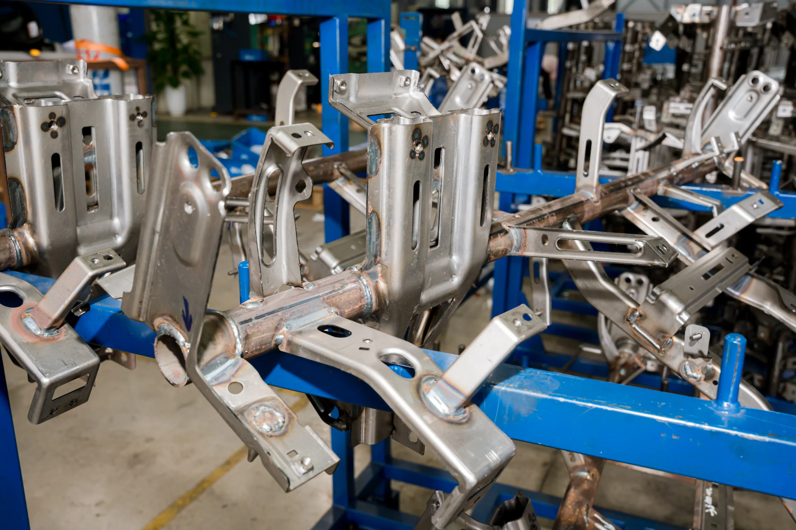
Tubular Cross Car Beam (CCB) structure with welded mounting brackets, stored on a transport rack.
4. Materials Used in Car Beam Manufacturing
4.1 High-Strength Steel (HSS)
4.1.1 Mechanical Properties
Yield strengths ranging from 210 MPa to 550 MPa, offering superior yield performance over standard mild steel without sacrificing formability.
4.1.2 Automotive Applications
Used in non-critical exterior crash zones, underbody cross-members, and mounting bracketry requiring moderate load-bearing capacity.
4.2 Advanced High Strength Steel (AHSS)
4.2.1 Weight Reduction Benefits
Tensile strengths from 500 MPa to over 1500 MPa (Dual Phase, TRIP, and Martensitic/Boron Press Hardened Steels), allowing thinner material gauges while maintaining yield limits.
4.2.2 Crash Performance
Provides high energy absorption rates in crash zones combined with ultra-high yield limits to construct non-yielding safety cage zones (B-pillars, door intrusion beams).
4.3 Aluminum Structural Beams
4.3.1 Lightweight Vehicle Design
Extruded (6xxx/7xxx series) or cast aluminum alloy beams deliver up to a 40–50% weight reduction compared to conventional steel configurations.
4.3.2 EV Applications
Crucial in Electric Vehicles (EVs) to offset heavy battery pack weight, extend driving range, and construct specialized battery enclosure protective side-beams.
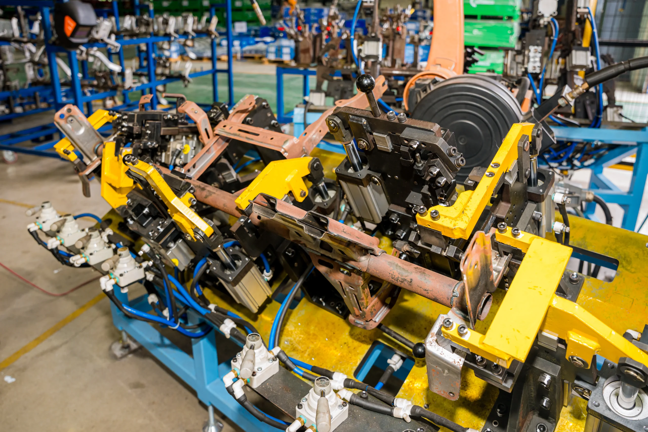
High-angle view of a complex pneumatic clamping fixture designed for robotic welding of structural chassis members.
5. Engineering Design Considerations
5.1 Structural Strength Requirements
5.1.1 Static Load Performance
Resistance to structural yield under continuous maximum static loads, including full vehicle payload, engine/battery weight, and towed loads.
5.1.2 Dynamic Load Resistance
Durability against fatigue failure caused by cyclic road inputs, high-g acceleration, sudden braking, and severe chassis twisting forces over vehicle service life.
5.2 Crash Safety Requirements
5.2.1 Impact Energy Absorption
Engineering controlled collapse mechanisms (folding modes, axial crumpling) into beam cross-sections to absorb maximum kinetic energy per unit mass.
5.2.2 Occupant Protection Standards
Compliance with global crash regulations, including FMVSS (USA), ECE (Europe), and C-NCAP/Euro NCAP crash safety protocols.
5.3 NVH Optimization
5.3.1 Vibration Control
Designing cross-sectional geometry to shift global structural resonance frequencies away from engine idle speeds and tire rotation frequency spectrums.
5.3.2 Noise Reduction
Preventing hollow acoustic resonance channels within tubular beams by adding structural foam inserts or localized damping baffles.
5.4 Dimensional Accuracy
5.4.1 GD&T Requirements
Applying strict Geometric Dimensioning & Tolerancing (GD&T) to hole patterns, surface profiles, and interface points to ensure repeatable fitments.
5.4.2 Assembly Fitment
Maintaining tolerance stack-ups within strict ranges across multi-component welded beam sub-assemblies.
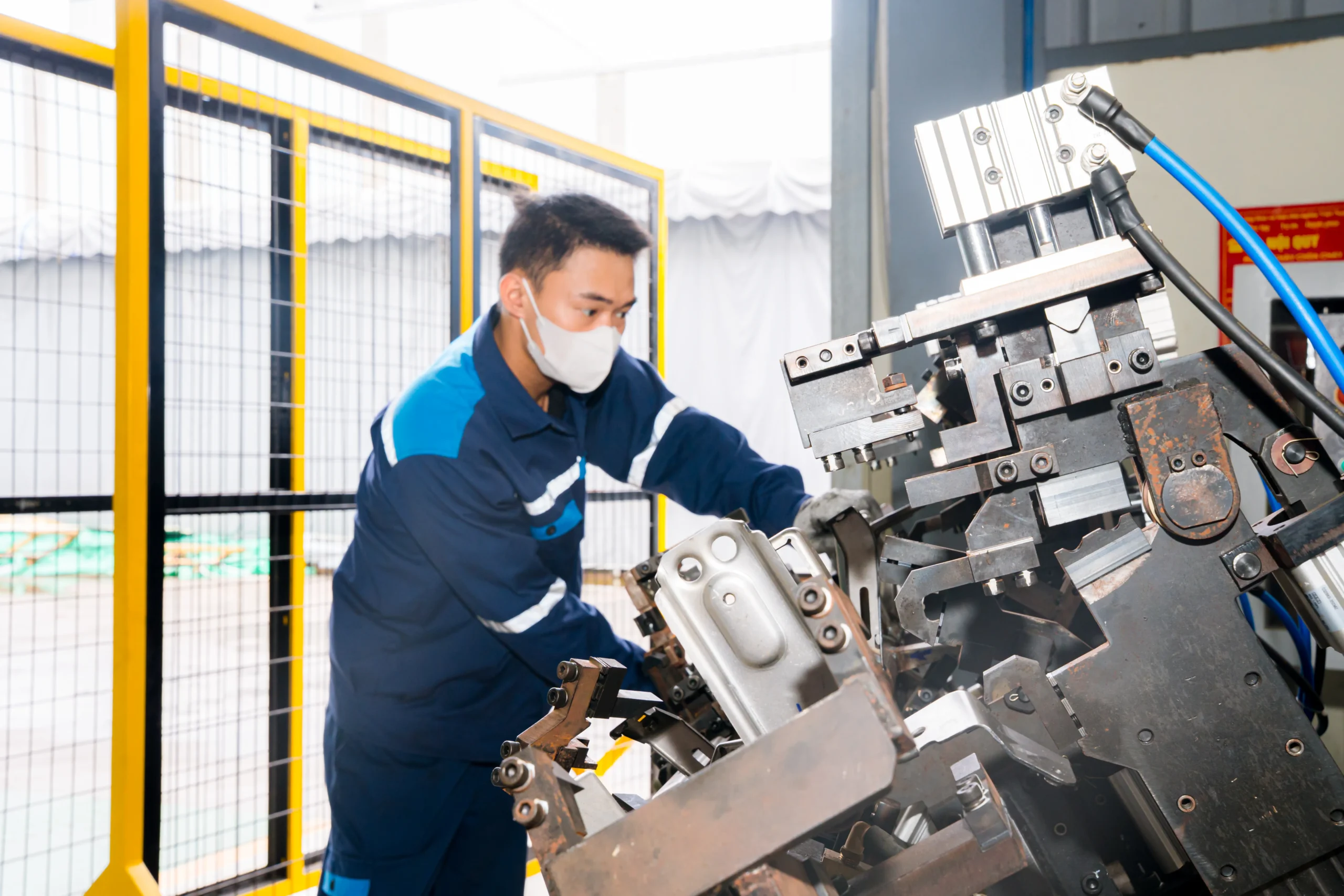
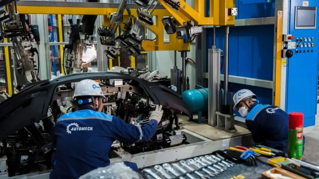
Technician adjusting component positioning on a pneumatic welding fixture within a robotic cell.
6. Automotive Quality & Manufacturing Standards
6.1 Quality Management Systems
6.1.1 ISO 9001
Base quality management standard establishing general organizational consistency, process documentation, continuous improvement, and leadership accountability.
6.1.2 IATF 16949
The mandatory automotive-specific quality standard governing defect prevention, supply chain variability reduction, and waste elimination across all tier levels.
6.2 Automotive Core Tools
6.2.1 APQP
Advanced Product Quality Planning: A structured framework covering concept development, process design, product validation, and volume ramp-up.
6.2.2 PPAP
Production Part Approval Process: Standardized documentation proving that manufacturing lines can consistently produce parts meeting all OEM specifications at target production speeds.
6.2.3 FMEA
Failure Mode and Effects Analysis: Proactive evaluation of potential design (DFMEA) and process (PFMEA) failure modes to mitigate risks before production setup.
6.2.4 Control Plan
A detailed operational document listing all process control parameters, inspection frequencies, sample sizes, and reaction plans for every step of beam production.
6.2.5 MSA
Measurement System Analysis: Statistical studies (e.g., Gauge R&R) evaluating the precision, bias, stability, and repeatability of checking tools and CMM systems.
6.2.6 SPC
Statistical Process Control: Real-time monitoring of critical product characteristics using control charts to catch process drift before defect creation.
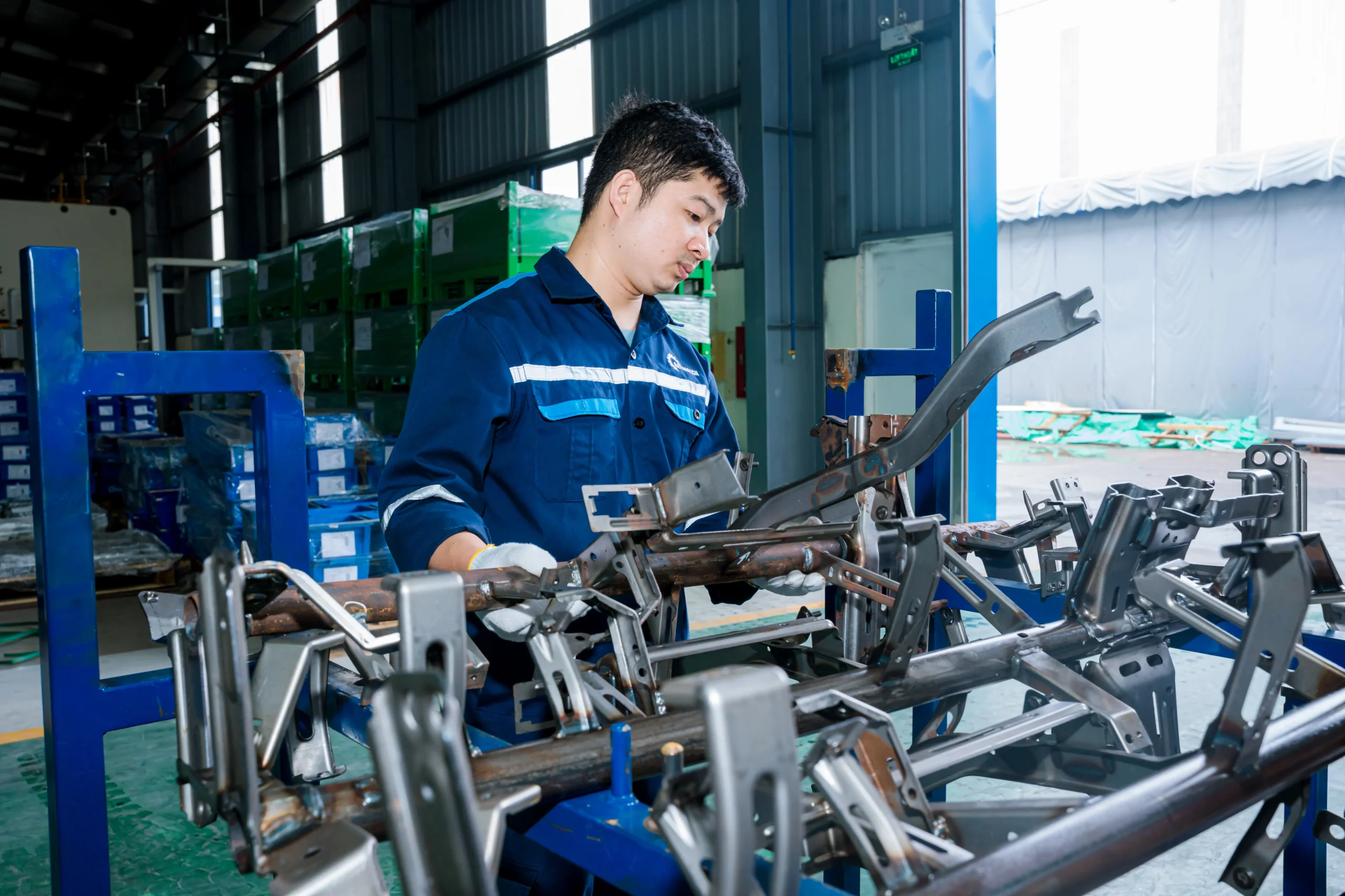
Technician inspecting dimensional alignment and weld quality on a tubular chassis assembly.
6.3 Inspection & Validation
6.3.1 CMM Inspection
Coordinate Measuring Machines (CMM) verifying complex 3D geometry against CAD models to fractional millimeter accuracy.
6.3.2 Fixture Validation
Routine verification of custom go/no-go checking fixtures using master models and CMM calibration to avoid false measurement readings.
6.3.3 Weld Inspection
Destructive cut-and-etch macro-examination alongside non-destructive ultrasonic scanning to evaluate weld nugget penetration and porosity limits.
6.3.4 First Article Inspection (FAI)
Complete measurement, material test certification, and dimensional validation of the initial parts produced from new tooling setups.
6.3.5 Full Traceability System
Laser-etched QR codes or serial stamping tracking batch raw material heat numbers, press line parameters, robot welding logs, and inspection records per part.
7. OEM Manufacturing & Sourcing Requirements
7.1 OEM Supplier Qualification
7.1.1 Engineering Capability
In-house structural engineering teams capable of co-design, CAD modification, CAE simulation, and DFM optimization alongside OEM engineers.
7.1.2 Manufacturing Capacity
Adequate press force tonnage, automated welding cells, footprint expansion space, and secondary processing capabilities to match OEM production run volumes.
7.1.3 Quality Assurance
Proven track record of zero-defect quality metrics (low PPM performance), robust core tools deployment, and IATF 16949 certification.
7.1.4 Export Compliance
Fulfillment of international shipping, logistics packaging, tariff compliance, Customs-Trade Partnership Against Terrorism (C-TPAT), and trade regulations.
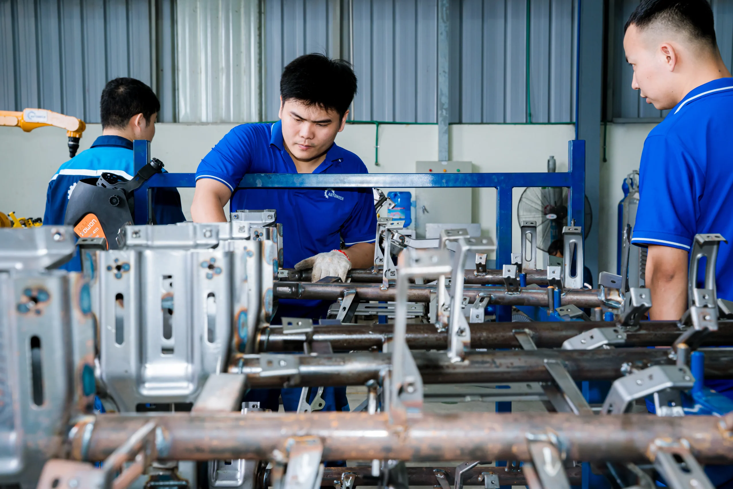
QC technicians performing manual alignment and dimensional verification on welded chassis assemblies.
7.2 Prototype to Mass Production
7.2.1 Prototype Manufacturing
Low-volume, soft-tooled (or laser-cut/hand-formed) prototype beam builds used for OEM vehicle testing, fit-up checks, and early crash testing.
7.2.2 Pilot Production
Pre-production runs (Off-Tool/Off-Process) using mass-production tooling to validate cycle times, process control, tooling ergonomics, and PPAP submission requirements.
7.2.3 Mass Production
Fully ramped continuous production under strict SPC controls with automated JIT line feeding and real-time inventory management.
8. Car Beam Cost & Pricing Factors
8.1 Material Selection
8.1.1 Steel Grade
Base material costs increase progressively from standard Low Carbon Steels to HSS, AHSS, and Ultra-High-Strength Press-Hardened Steels.
8.1.2 Aluminum Grade
Aluminum alloys carry a higher raw material premium per kilogram compared to steel, though offset partially by light-weighting benefits and processing efficiency.
8.2 Manufacturing Complexity
8.2.1 Tooling Cost
Capital expenditures for multi-stage progressive dies, transfer dies, hydroforming tooling, and hot-stamping press dies impact unit pricing amortization.
8.2.2 Welding Complexity
The count, type, and density of welds (spot, MIG, laser) alongside custom assembly fixture needs directly determine cycle times and labor/robotics overhead.
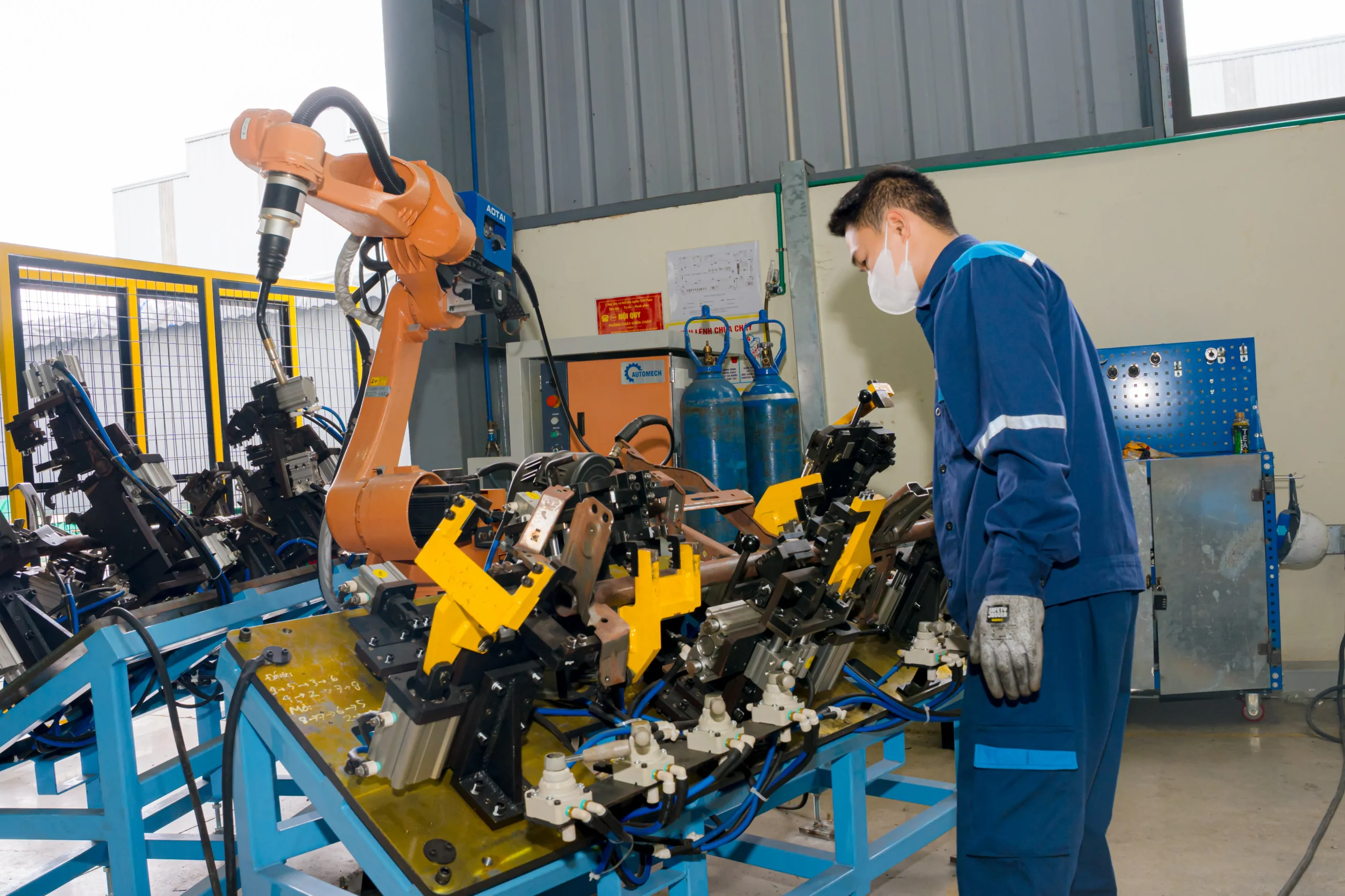
Operator reviewing part alignment on pneumatic fixtures before automated robotic welding cycles.
8.3 Production Volume
8.3.1 Low Volume
Niche or luxury vehicle programs amortize high fixed tooling and engineering setup costs across fewer total production units, yielding higher per-part prices.
8.3.2 High Volume
Mass-market vehicle programs achieve high economies of scale, significantly reducing piece prices through automated cell utilization and raw material bulk purchasing.
8.4 Quality & Inspection Requirements
Stringent 100% automated inline optical scanning, destructive testing frequencies, specialized coatings, and individual traceability serialization add incremental unit costs.
9. How to Choose a Car Beam Manufacturer
9.1 Engineering Capability
9.1.1 BIW Experience
Proven historical track record in delivering structural Body-in-White components that meet global automotive safety and assembly fit standards.
9.1.2 Structural Engineering Expertise
Demonstrated ability to run FEA analysis, propose weight-saving material substitutions, and optimize beam designs for manufacturing efficiency.
9.2 Manufacturing Capability
9.2.1 Stamping Equipment
Availability of high-tonnage mechanical, hydraulic, and servo presses capable of processing thick-gauge, high-strength metals cleanly.
9.2.2 Welding Automation
Deployment of robotic multi-axis welding cells that guarantee consistent weld placement, correct nugget size, and repeatable strength.
9.2.3 Tooling Development
In-house or closely partnered die design, machining, maintenance, and modification capabilities to ensure rapid repairs and process adjustments.
9.3 Quality Systems
9.3.1 Automotive Certifications
Mandatory active IATF 16949 certification verified by accredited third-party auditing bodies.
9.3.2 Inspection Equipment
Availability of calibrated, modern quality control hardware including CMMs, optical scanners, ultrasonic weld testers, and tensile test equipment.
9.4 Export Experience
9.4.1 US Market
Familiarity with US automotive standards (FMVSS, SAE), logistics management to North American ports, and tier-level inventory buffer requirements.
9.4.2 European Market
Proven compliance with European OEM standards (VDA quality framework, REACH, RoHS environmental directives) and European shipping logistics.
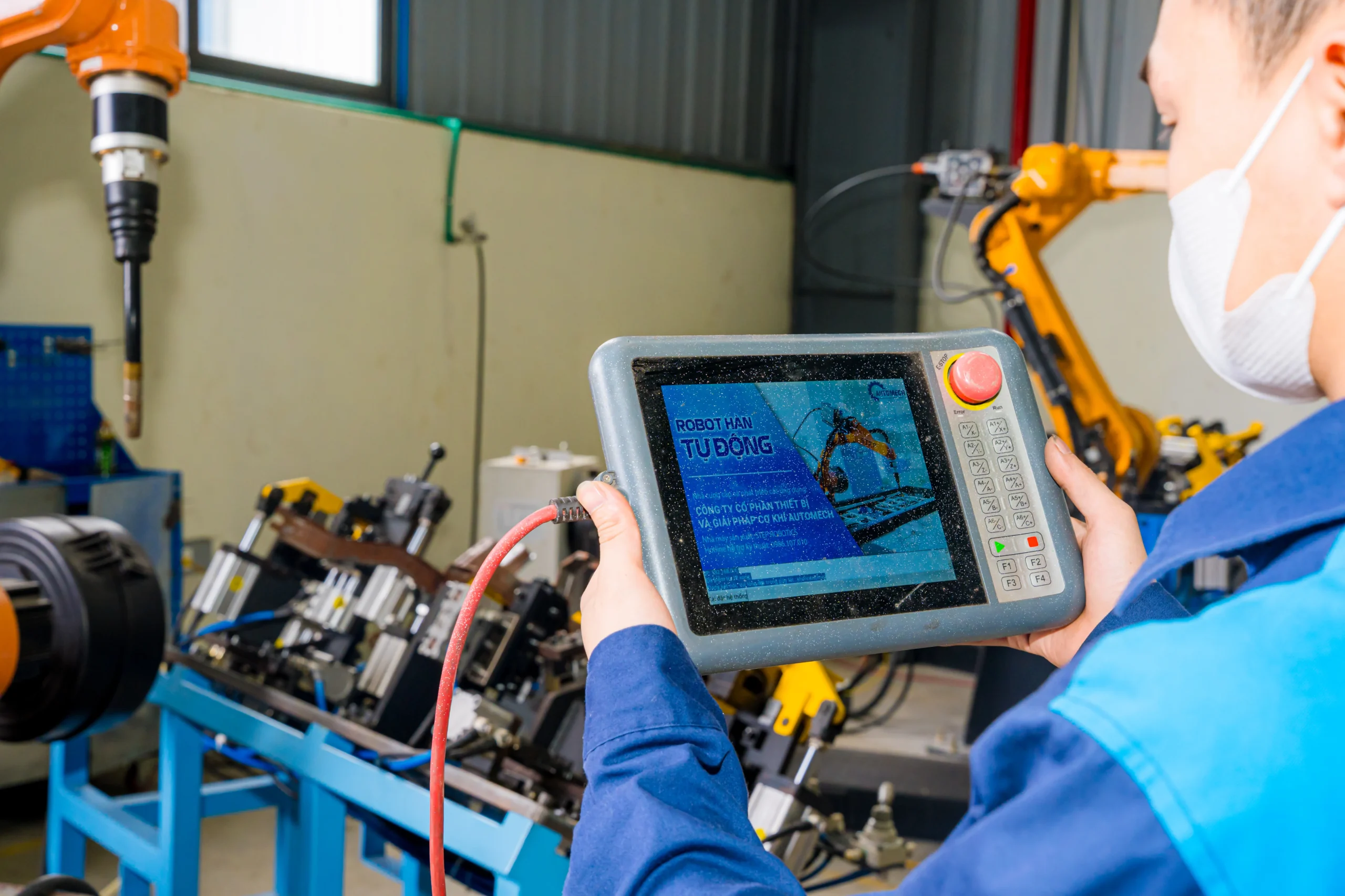
Close-up of an operator using a handheld teach pendant displaying AUTOMECH control software for robot programming.
10. RFQ Process for Automotive Car Beams
10.1 Required Technical Documents
10.1.1 CAD Drawings
Native 3D CAD models (STEP, IGES, CATIA files) defining full spatial geometry, surface interfaces, and mounting points.
10.1.2 GD&T Requirements
2D technical engineering drawings explicitly marking critical-to-quality dimensions, datum schemes, surface profiles, and tolerance bands.
10.1.3 Material Specifications
Clear callouts of material grades, standards (e.g., EN, ASTM, JIS, OEM specific specs), sheet thickness, surface treatments, and plating requirements.
10.2 Engineering Review
10.2.1 DFM Analysis
Reviewing part geometry to identify risk points like tight bend radii, potential draw wrinkling, springback tendencies, or poor weld accessibility.
10.2.2 Tooling Feasibility
Evaluating required press tonnage, draw station counts, die materials, and structural fixture layouts to confirm manufacturing viability.
10.3 Quotation & Project Planning
10.3.1 Cost Breakdown
Itemized quotations detailing raw material piece cost, manufacturing conversion cost, surface treatment, packaging, tooling capital expense, and fixture fees.
10.3.2 Lead Time
Detailed scheduling covering die design, tooling build, trial press runs, prototype delivery, sample validation, and full production launch dates.
10.3.3 PPAP Timeline
A structured roadmap identifying key milestones for APQP deliverables, FMEA creation, tool tryouts, gauge construction, and final PPAP submission levels.
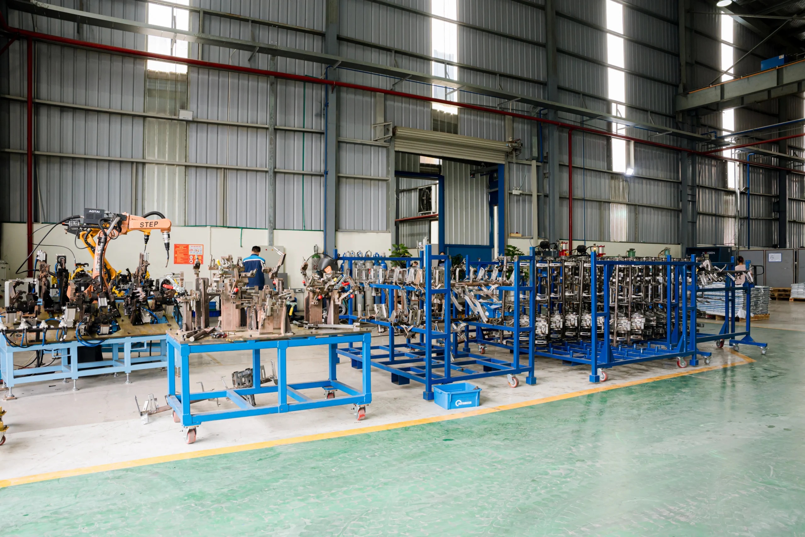
Panoramic view of the fabrication shop featuring robotic cells and organized assembly fixture stations.
11. Why Global OEMs Source Car Beams from Vietnam
11.1 Competitive Manufacturing Costs
11.1.1 China+1 Supply Chain Strategy
Global OEMs and Tier 1 suppliers actively diversify their manufacturing footprints outside of China into Vietnam to minimize geopolitical and supply chain disruption risks.
11.1.2 Cost Efficiency
Favorable labor rates paired with highly competitive factory overheads allow high-precision, labor-assisted automated manufacturing at lower total cost.
11.2 Advanced Manufacturing Capability
11.2.1 Precision Metal Stamping
Continuous capital investment in modern servo-driven press lines, multi-station progressive stamping, and heavy tonnage forming capacity.
11.2.2 Robotic Welding Assembly
Widespread deployment of Japanese and European robotic welding automation ensuring high repeatability and OEM-grade structural weld integrity.
11.3 Export Manufacturing Experience
11.3.1 US Automotive Market
Vietnam-based manufacturers maintain strong export channels delivering stamped and welded automotive components directly into US assembly ecosystems.
11.3.2 European Automotive Market
Fulfillment of strict European environmental, quality, and traceability standards with direct sea freight connectivity to major European trade ports.
11.4 Stable Supply Chain
11.4.1 Quality Consistency
Broad adoption of international automotive quality management frameworks (IATF 16949) ensuring predictable low-PPM output across high production runs.
11.4.2 Flexible Production Capacity
Agile manufacturing operations structured to scale rapidly from mid-volume specialized platforms to high-volume global vehicle programs.
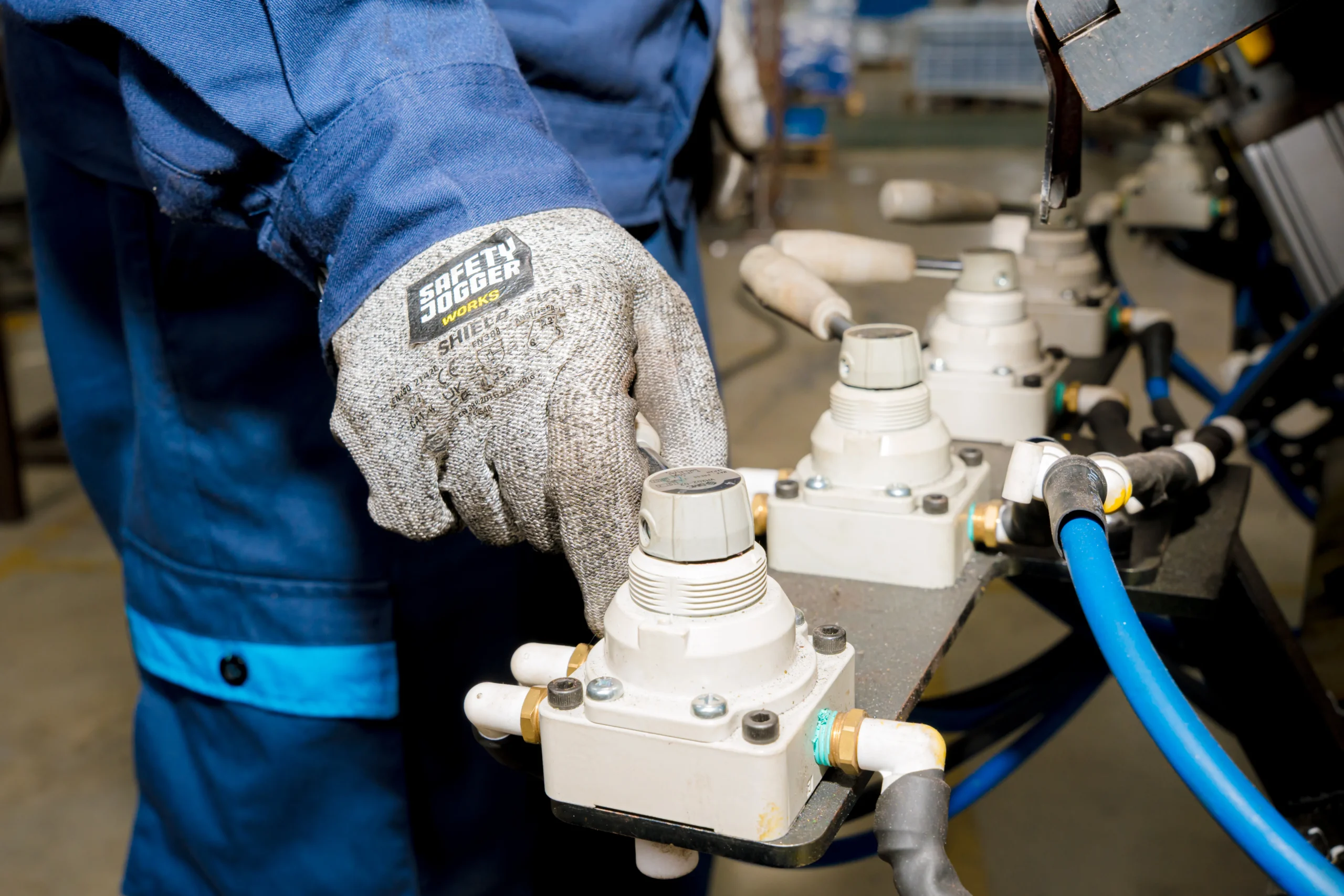
Operator activating pneumatic pressure valves to securely lock parts into position on the welding fixture.
12. Why Choose Automech as Your Car Beam Manufacturer in Vietnam
12.1 Automotive Metal Stamping Capability
12.1.1 Progressive Die Stamping
High-speed, multi-station progressive die presses optimized for producing structural brackets, mounting plates, and structural beam sub-components with maximum efficiency.
12.1.2 Structural Component Manufacturing
Large-tonnage press lines engineered to form heavy-gauge High-Strength Steel and Advanced High-Strength Steel structural members.
12.2 Automotive Welding Assembly Systems
12.2.1 Robotic Welding
Fully integrated multi-axis robotic spot and MIG welding cells producing consistent, high-integrity welds on complex cross-car and structural beam assemblies.
12.2.2 Fixture-Controlled Assembly
Custom pneumatic welding fixtures holding spatial dimensional tolerances tightly during joining processes to prevent thermal distortion.
12.3 BIW Manufacturing Expertise
12.3.1 Structural Beam Production
Specialized production lines geared specifically toward cross-car beams, front bumper beams, side intrusion bars, and underbody structural chassis members.
12.3.2 OEM Vehicle Programs
Direct experience acting as a reliable Tier 1 and Tier 2 manufacturing partner for commercial and passenger vehicle programs globally.
12.4 Automotive Tooling & Fixture Capability
12.4.1 Stamping Dies
Comprehensive engineering and maintenance support for progressive, transfer, and single-stage stamping dies built for high durability and tight tolerances.
12.4.2 Welding Fixtures
In-house design and fabrication of heavy-duty, high-precision assembly welding fixtures equipped with sensors and mechanical clamps.
12.4.3 Checking Fixtures
Custom CMM-verified checking fixtures and Go/No-Go gauges built specifically for offline operator quality checks and line validation.
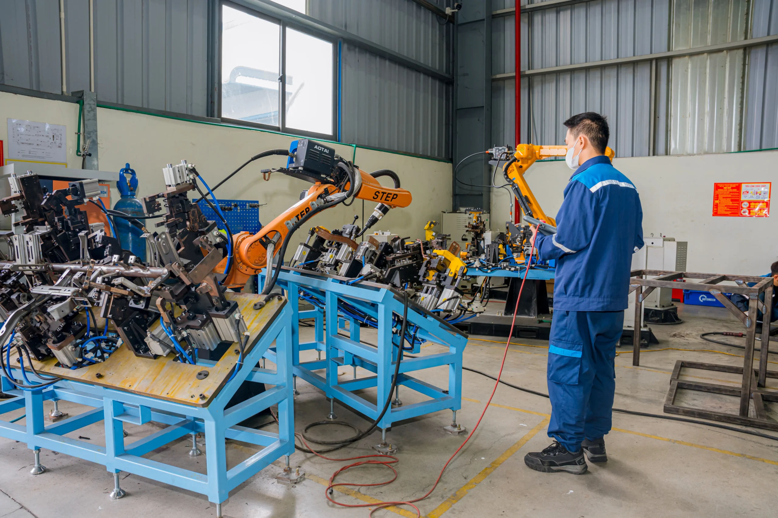
A technician operating a teach pendant to control a multi-axis robotic welding cell.
12.5 Quality Assurance
12.5.1 CMM Inspection
Fully equipped Metrology labs utilizing automatic CMM systems to run comprehensive dimensional checks against client CAD models.
12.5.2 Full Traceability
Complete raw material-to-finished-goods serialization system, guaranteeing complete visibility over material heats, welding logs, and inspection checks.
12.5.3 Automotive Core Tools
Routine internal deployment of APQP, PPAP, FMEA, Control Plans, MSA, and real-time SPC metrics to ensure continuous quality control.
12.6 Engineering Support
12.6.1 DFM Review
Dedicated engineering review evaluating your technical drawings to suggest material, geometry, and process optimizations before tooling cuts.
12.6.2 Manufacturing Feasibility Analysis
In-depth feasibility studies analyzing press tonnage requirements, springback behavior, and weld accessibility to guarantee successful production.
12.6.3 Prototype to Mass Production
End-to-end project execution, supporting your program smoothly from initial low-volume prototype builds through PPAP sign-off and continuous mass production.
12.7 CTA
12.7.1 Request an RFQ
Send your structural car beam specifications and volume targets to our engineering team to receive a competitive manufacturing quotation.
12.7.2 Upload CAD Drawings
Upload your 3D CAD models (STEP/IGES) and 2D GD&T prints directly through our secure engineering portal for a quick feasibility analysis.
12.7.3 Contact the Automotive Engineering Team
Speak directly with our senior automotive structural engineers to discuss technical material requirements, weld specifications, and program timelines.
12.7.4 Request a Manufacturing Feasibility Review
Submit your current part design for a complete, complimentary Design for Manufacturability (DFM) and tooling feasibility report.
12.7.5 Download Company Capability Profile
Download our full manufacturing capability overview to explore our equipment lists, press capacities, robotic welding setups, and ISO/IATF certifications.
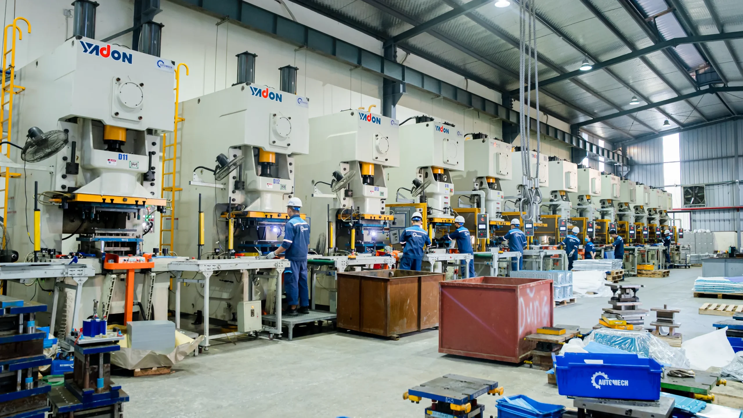
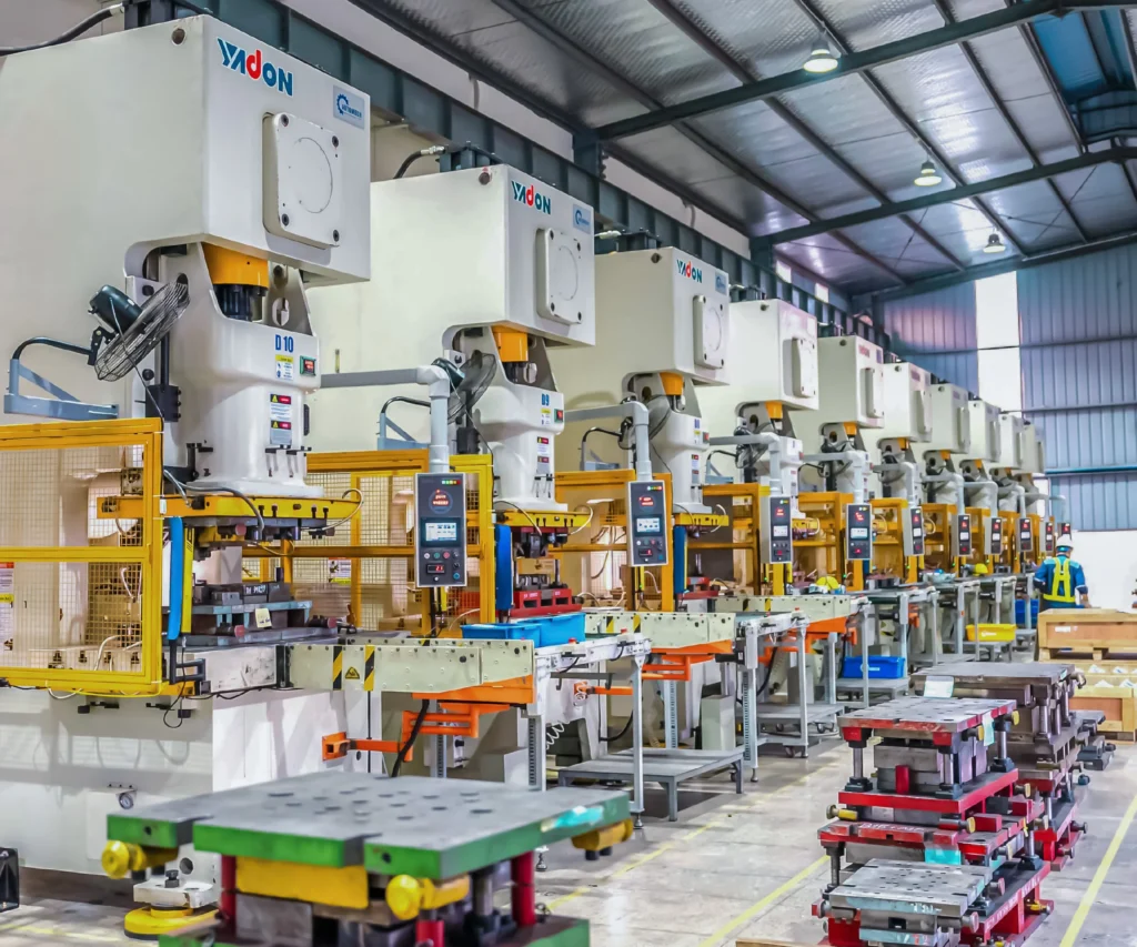
Modern stamping shop with a line of heavy-tonnage YADON mechanical presses operated by workers.
13. Featured Snippet Opportunities
13.1 Definition Snippet
13.1.1 What Is a Car Beam?
A car beam is a load-bearing structural component in a vehicle’s body-in-white (BIW) frame designed to distribute mechanical loads, absorb crash impact energy, and increase overall chassis rigidity. Examples include cross-car beams, front/rear bumper beams, and door intrusion beams, typically made from High-Strength Steel (HSS), Advanced High-Strength Steel (AHSS), or extruded aluminum.
13.2 List Snippet
13.2.1 Types of Automotive Car Beams
- Cross Car Beam (CCB): Spans between A-pillars behind the dashboard to support steering columns, HVAC, and instrument panels.
- Front Car Beam: Located behind the front bumper to absorb frontal impact energy and reinforce front frame rails.
- Rear Car Beam: Protects the vehicle tail section, rear passengers, fuel tanks, and EV batteries from rear-end collisions.
- Instrument Panel (IP) Beam: Serves as the structural skeleton inside the cockpit for module integration and side-impact protection.
- Side Reinforcement Beams: Door intrusion beams designed to prevent cabin penetration during side-impact crashes.
- Roof Reinforcement Beams: Roof bows connecting side rails to ensure roof crush resistance during rollovers.
13.3 Process Snippet
13.3.1 Car Beam Manufacturing Process
- Engineering Design & DFM: 3D CAD modeling, CAE crash simulation, and DFM feasibility analysis.
- Metal Stamping: Forming structural parts via progressive die or transfer press stamping.
- Robotic Welding Assembly: Joining stampings and tubes using automated spot, MIG, or laser welding cells.
- Quality Inspection: Verifying dimensions via CMM, checking fixtures, and destructive/non-destructive weld testing.
- BIW Integration: Final alignment checks and delivery to the vehicle body assembly line.
13.4 Comparison Table
13.4.1 Cross Car Beam vs Front Car Beam
| Feature | Cross Car Beam (CCB) | Front Car Beam |
| Primary Location | Cockpit area (between A-pillars behind dashboard) | Front end (behind front bumper system) |
| Main Function | Cockpit module support & side-impact load transfer | Frontal crash energy absorption & rail tie |
| Supported Components | Steering column, HVAC, airbags, instrument panel | Bumper fascia, crash boxes, radiator supports |
| Dominant Stress Types | Torsional stiffness, vibration damping, lateral loads | High kinetic impact force compression |
| Common Materials | Tubular steel, hydroformed steel, die-cast aluminum | High-Strength Steel (HSS), Press-Hardened Steel |
13.5 Comparison Table
13.5.1 Steel vs Aluminum Car Beams
| Metric / Parameter | Steel Car Beams (HSS / AHSS) | Aluminum Car Beams (Extruded / Cast) |
| Material Weight | Heavier baseline weight | 40% – 50% lighter than conventional steel |
| Tensile Strength | Extremely high (up to 1500+ MPa for AHSS/Boron) | Moderate to High (typically 250 – 400 MPa) |
| Raw Material Cost | Lower material cost | Higher material cost per kilogram |
| Forming Process | Stamping, roll forming, hot pressing | Extrusion, die casting, hydroforming |
| Primary Application | High-crash load areas, mass-market platforms | Electric Vehicles (EVs), premium light-weighting |
13.6 Checklist Snippet
13.6.1 How to Choose a Car Beam Supplier
[✓] Automotive Certification: Verify active IATF 16949 quality certification.
[✓] In-House Engineering: Confirm DFM, CAE simulation, and CAD capability (CATIA/NX).
[✓] Stamping Capacity: Check press tonnage and availability of progressive/transfer die lines.
[✓] Welding Automation: Ensure multi-axis robotic MIG/Spot/Laser welding setups.
[✓] Metrology Equipment: Verify in-house CMM, laser scanning, and weld testing labs.
[✓] Core Tools Mastery: Ensure full execution of APQP, PPAP, FMEA, MSA, and SPC protocols.
[✓] Export Logistics: Check proven track record shipping to North American or European automotive markets.
Stamped sheet metal mounting bracket featuring embossed reinforcement and pre-punched positioning holes.
14. People Also Ask (PAA)
14.1 What is a car beam in automotive manufacturing?
A car beam is a primary structural component engineered to absorb impact forces, distribute dynamic loads, and strengthen a vehicle’s chassis frame (BIW). Located across areas like the dashboard, front bumper, rear tail, and doors, these beams protect occupants and support internal subsystems.
14.2 What is the function of a cross car beam?
A cross car beam (CCB) spans across the front cabin between the A-pillars behind the dashboard. It supports the steering column, driver/passenger airbags, HVAC unit, and instrument cluster while providing vital transverse rigidity that absorbs side-impact forces during collisions.
14.3 What materials are used for automotive car beams?
Automotive car beams are mainly produced from High-Strength Steel (HSS), Advanced High-Strength Steel (AHSS) such as Dual Phase or Boron press-hardened steel, and high-strength extruded or die-cast Aluminum alloys chosen to reduce overall vehicle weight.
14.4 How are car beams manufactured?
Car beams are manufactured by precision metal stamping (progressive or transfer dies), tube bending, or hydroforming. The individual stamped components and structural brackets are then joined using robotic spot, MIG, or laser welding before undergoing CMM dimensional verification.
14.5 What is BIW manufacturing?
Body in White (BIW) manufacturing refers to the assembly stage in automotive production where a vehicle’s sheet metal structural frame—including beams, pillars, roof rails, and floor pans—is welded together before the integration of the drivetrain, powertrain, or interior trim.
14.6 How do I choose a reliable car beam supplier?
Select a supplier with active IATF 16949 certification, robust heavy-tonnage stamping presses, multi-axis automated robotic welding systems, in-house CMM metrology capabilities, full APQP/PPAP engineering support, and proven automotive export experience.
14.7 Why do OEMs source automotive structural components from Vietnam?
Global OEMs source structural components from Vietnam due to competitive production costs, advanced technical investments in precision stamping and robotic welding, robust automotive quality systems, and effective supply chain diversification strategies (China+1).
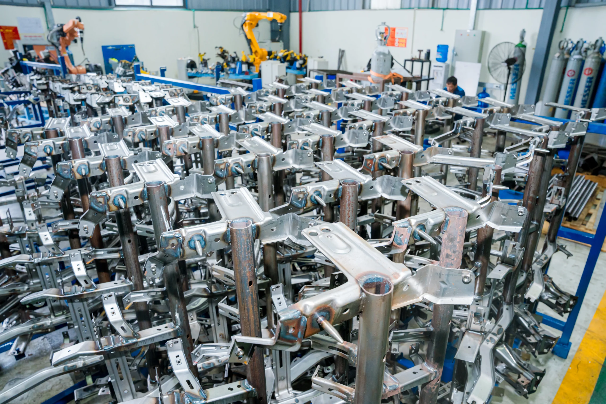
High-density storage rack holding completed tubular steel chassis subassemblies prior to coating.
15. FAQ
15.1 What is the difference between a cross car beam and a front car beam?
A cross car beam is mounted inside the vehicle cockpit behind the instrument panel to support steering systems and absorb lateral side-impact forces. A front car beam is located behind the front bumper fascia, engineered primarily to crumple predictably and absorb kinetic energy during frontal collisions.
15.2 Which materials provide the best strength-to-weight ratio for car beams?
Advanced High-Strength Steels (AHSS) like hot-stamped Boron steel offer unmatched absolute strength-to-weight ratios for safety cage components. However, extruded aluminum alloys provide superior total weight reduction for electric vehicle applications where mass reduction is critical.
15.3 Can aluminum replace steel in automotive structural beams?
Yes, aluminum can replace steel in many structural beam applications, offering up to a 50% weight savings. However, aluminum requires different structural cross-section designs, specialized joining techniques (such as self-piercing rivets, MIG, or laser welding), and carries higher raw material costs.
15.4 What automotive quality certifications should a supplier have?
At a minimum, an automotive structural beam supplier must hold IATF 16949 certification for automotive quality management and ISO 9001. Environmental certifications like ISO 14001 and occupational health standards like ISO 45001 are also standard requirements for Tier 1 suppliers.
15.5 What information is required to request a car beam RFQ?
To issue a comprehensive Request for Quotation (RFQ), you need to provide 3D CAD files (STEP/IGES), 2D drawings with GD&T callouts, material grade specifications, annual production volumes, surface finishing requirements, target delivery dates, and required PPAP submission levels.
15.6 How long does prototype-to-production typically take?
The prototype-to-mass-production lifecycle generally ranges from 24 to 36 weeks. This timeline includes DFM analysis, soft prototype tool creation (4–6 weeks), hard mass-production die and welding fixture manufacturing (12–16 weeks), trial press runs, and full PPAP Level 3 approval before mass production launch.
15.7 Why choose a Vietnamese car beam manufacturer over other sourcing destinations?
Vietnamese manufacturers like Automech offer a compelling balance of modern automated press/welding technology, full compliance with international IATF 16949 quality core tools, lower labor overheads, direct export shipping routes to major markets, and a stable supply chain environment ideal for China+1 diversification strategies.
Automech Mechanical Equipment and Solutions Joint Stock Company
Head Office: No. 285 Phuc Loi Street, Phuc Loi Ward, Hanoi City
Da Nang Branch: No. 20 Nguyen Sinh Sac Street, Hoa Khanh Ward, Da Nang City
Ho Chi Minh Branch: No. 84, Street No. 10, Van Phuc Urban Area, Hiep Binh Ward, Ho Chi Minh City
Factory No. 1: Automech Automation Equipment, Mold & Tool Manufacturing Factory – Automech Demo Center: Dinh Tram Industrial Park, Nenh Ward, Bac Ninh City, Vietnam
Factory No. 2: Automech Parts Manufacturing & Component Fabrication Factory: Viet Nhat Industrial Cluster, Xuan Cam Commune, Bac Ninh City, Vietnam
Hotline: 0902 997 331
Website: https://automechmfg.com/
Fanpage: https://www.facebook.com/automech.mfg/
YouTube: https://www.youtube.com/@Automechmfg