In automotive structural engineering, terms like “car cross“, “cross member”, and “cross car beam” (CCB) are fundamental to vehicle safety, torsional rigidity, and crash energy management. However, overlapping terminology often creates confusion for buyers, sourcing engineers, and OEMs. This comprehensive article provides an in-depth technical guide breaking down the structural differences between chassis cross members, dashboard cross car beams, and vertical B-pillars. Additionally, we explore advanced automotive stamping, robotic welding assembly, stringent GD&T inspection, and OEM supplier qualification standards.
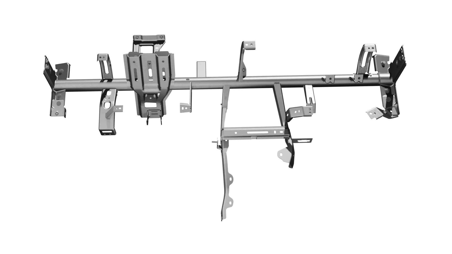
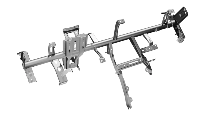
Cross Car Beam (CCB) Assembly – Precision Structural Component for Automotive Dashboards
1. What Does “Car Cross” Mean?
1.1 Understanding the Search Term “Car Cross”
1.1.1 “Car Cross” as a possible typo or incomplete automotive query
When searching for “car cross”, users are almost always entering an incomplete phrase or typographical variation of critical automotive structural components. In search query intent analysis, “car cross” correlates directly with primary structural members such as a car cross, chassis crossmember, or cross car beam (CCB). Engineers, automotive buyers, and technical procurement specialists using this search term are typically looking for detailed technical specifications regarding transverse load-bearing structural elements within the vehicle chassis or Body-in-White (BIW) assembly.
1.1.2 Common automotive terms related to “car cross”
To address the broad search intent behind this query, automotive structural terminology can be categorized into three distinct mechanical components:
- Car Cross / Cross Member: Transverse structural steel beams or cradles mounted across the underbody or chassis frame to tie longitudinal side rails together.
- Cross Car Beam (CCB): The primary interior safety structure spanning between the front A-pillars behind the instrument panel, acting as the structural anchor for steering column mounts and airbag modules.
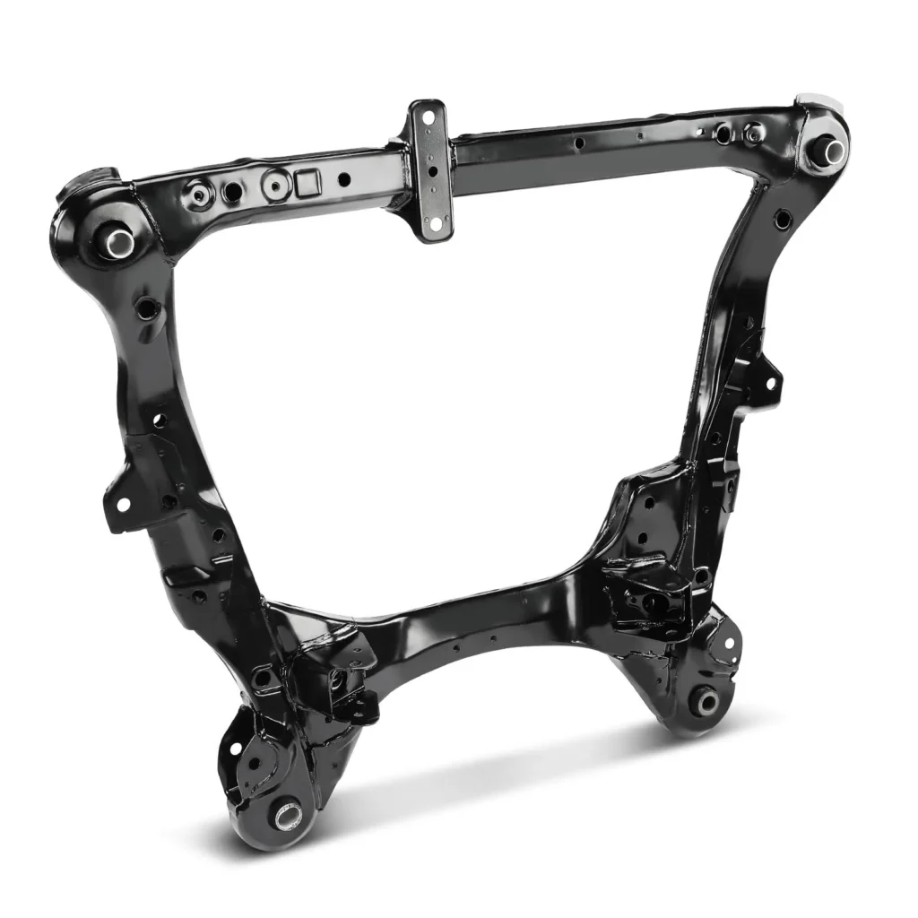
- Chassis Crossmember / Subframe: Structural assemblies designed to support heavy powertrain dynamic loads, steering gearboxes, and suspension control arm pivot points.
1.2 Car Cross, Cross Member and Cross Car Beam
1.2.1 Car cross
The term “car cross” is a generalized industry shorthand used to describe any transverse load-bearing structural profile within a vehicle’s framework. Installed perpendicular to the vehicle’s driving axis, a car cross ties opposing side panels, rocker panels, or side frame rails together. By creating rigid cross-bracing, it ensures the overall structural shell maintains dimensional stability when subjected to complex operational forces such as cornering torsion, braking acceleration, and dynamic road vibrations.
1.2.2 Cross member / crossmember
A cross member (frequently written as a single word, crossmember) is a heavy-gauge structural steel or extruded aluminum beam bolted or welded across the main frame rails of a vehicle. In body-on-frame truck architectures as well as modern unibody subframes, cross members serve as the backbone for torsional stiffness. They are specifically engineered to withstand harsh multi-axial fatigue loads while providing rigid mounting points for engine mounts, transmission tail housings, fuel tank straps, and differential assemblies.
1.2.3 Cross car beam
A cross car beam (CCB) is a highly engineered, safety-critical structural assembly located inside the vehicle cabin. Spanning directly between the left and right cowl side panels (front A-pillars) behind the main dashboard display, the CCB forms the primary structural bridge across the passenger compartment. Beyond serving as the backbone for the steering wheel column, passenger airbag module, and climate control (HVAC) ducting, the CCB plays a decisive role in crashworthiness, absorbing severe side-impact crash energy to prevent cabin intrusion.
1.3 Why Automotive Terminology Can Be Confusing
1.3.1 Cross member vs structural beam
Automotive terminology often blurs the line between a cross member and a generic structural beam. While both components carry load, a cross member strictly designates a transverse structural component engineered for multi-axis chassis reinforcement, dynamic suspension reactions, and crash energy paths. In contrast, a structural beam can refer broadly to any tubular or rolled section used anywhere in the BIW frame—such as roof bows, bumper reinforcement bars, or door impact beams—which may not necessarily tie opposing frame rails together.
1.3.2 Cross car beam vs dashboard beam
In non-technical conversations, the terms “cross car beam” and “dashboard beam” are sometimes used interchangeably, but they represent very different engineering scopes. A dashboard beam can refer to a lightweight internal plastic or thin-gauge sheet metal bracket meant purely to hold cosmetic trim and light wiring harnesses. Conversely, a Cross Car Beam (CCB) is a certified, crash-relevant structural safety component designed to resist severe crushing forces during side-impact collisions while eliminating steering column resonances (NVH control).
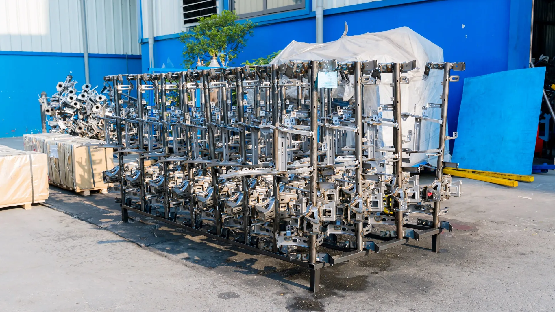
Batch Storage Rack of Finished Cross Car Beam (CCB) Assemblies Ready for Shipment
2. What Is a Cross Member on a Car?
2.1 Cross Member Definition
2.1.1 Position within the vehicle body structure
A cross member occupies strategic transverse locations along the lower vehicle architecture. In ladder-frame trucks and SUVs, cross members connect the left and right longitudinal frame channels from the front radiator support all the way to the rear towing crossmember. In passenger unibody vehicles, stamped floor cross members are welded directly across the floor pan between the inner rocker panels, providing localized structural reinforcement under the front and rear seating tracks.
2.1.2 Main structural functions
The structural utility of an automotive cross member revolves around three mechanical imperatives:
- Torsional Stiffness: It prevents the parallel longitudinal frame rails from twisting independently when driving over uneven terrain or speed bumps.
- Structural Geometry Maintenance: It ensures fixed dimensional spacing between critical suspension mounting points, preserving alignment angles (toe, camber, caster).
- Crash Load Redistribution: In the event of a frontal offset or side impact, cross members distribute severe localized impact forces across the entire floor pan structure, shielding the passenger cabin.
2.2 What Does a Cross Member Do on a Car?
2.2.1 Improve body rigidity
Without cross members, a vehicle frame would behave like a flexible ladder, bending under cornering forces and flexing over road bumps. By locking opposing longitudinal structural channels into a rigid box-like grid, cross members dramatically increase torsional rigidity. This increased stiffness minimizes body flex, which improves vehicle handling responsiveness, steering precision, and driver feedback.
2.2.2 Distribute structural loads
During acceleration, heavy braking, or trailer towing, massive dynamic loads pass through the suspension into the frame. Cross members act as internal load distributors, transferring localized point loads away from individual mounting brackets and dispersing stress evenly across the full width of the vehicle frame, effectively mitigating structural metal fatigue.
2.2.3 Support vehicle components
Engineers utilize cross members as robust mounting foundations for vital mechanical systems. These include:
- Engine and transmission mounts (absorbing powertrain torque reactions).
- Steering gearboxes and front/rear suspension control arms.
- Exhaust hangers, driveshaft center support bearings, and fuel tank safety straps.
2.3 Cross Member vs Crossmember of a Car
2.3.1 Terminology and engineering usage
From an engineering, manufacturing, and technical documentation perspective, “cross member” and “crossmember” are completely synonymous. The two-word spacing “cross member” is widely favored in American automotive engineering publications (SAE) and formal OEM technical drawings. The single-word variant “crossmember” is commonly used in aftermarket catalogs, maintenance manuals, and international trade listings. Both refer to identical physical components.
2.3.2 Structural applications
Whether spelled as one word or two, these components cover both full-length body-on-frame crossmembers and modular unibody subframes. In modern automotive engineering, subframe crossmembers are designed as removable modular cradles that hold the entire powertrain and front suspension assembly, allowing streamlined drop-in integration on the main assembly line.
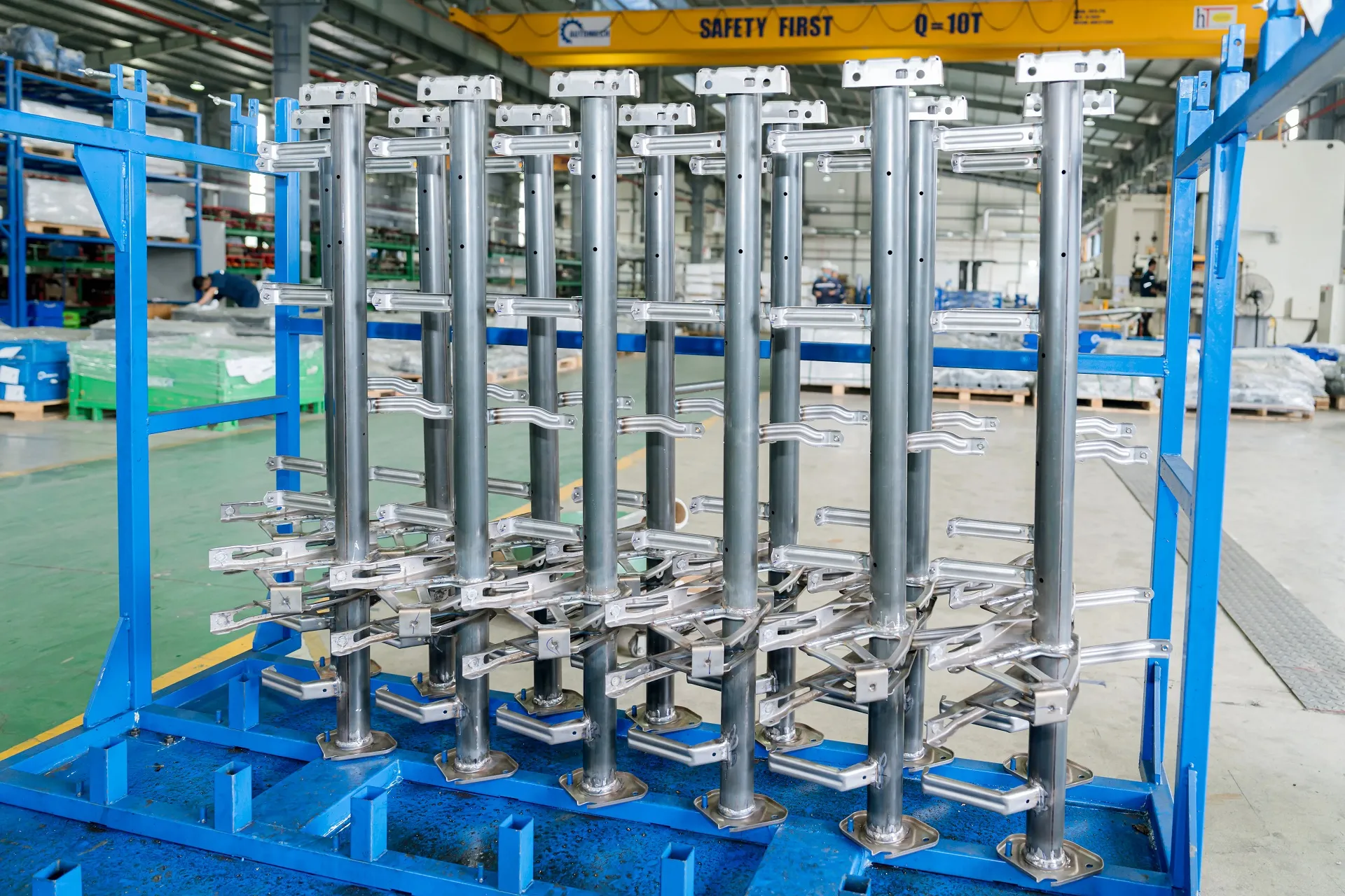
Vertical Storage Racks for Precision-Welded Cross Car Beam Assemblies inside Workshop
3. What Is a Cross Car Beam?
3.1 Cross Car Beam Definition
3.1.1 Dashboard cross beam
The Cross Car Beam (CCB), often designated as the dashboard cross beam, is a complex, multi-bracketed structural tube or box-section assembly located directly under the dashboard cowling. It spans the entire interior width of the cockpit, linking the left and right front A-pillars into a unified transverse structural unit.
3.1.2 Instrument panel cross car beam
As the primary structural support for the entire Instrument Panel (IP) module, the CCB serves as the rigid mounting frame for essential vehicle hardware. It holds the heavy steering column assembly, driver and passenger airbag deployment modules, climate control unit (HVAC), center console infotainment, fuse boxes, and intricate wire harness routing clips.
3.2 Cross Car Beam Location
3.2.1 Position between vehicle side structures
The CCB is anchored inside the cabin forward of the driver and front passenger seats. Its terminal ends are bolted or welded directly to the lower A-pillar cowl side inner panels. This strategic positioning places the heavy beam at the ideal height to brace the front cabin against lateral side impacts.
3.2.2 Connection with surrounding body structures
To maximize structural efficiency, the CCB does not float independently; it is integrated into adjacent BIW structures via reinforced brackets. Diagonal braces connect the central span of the CCB down to the floor tunnel, while upper brackets tie into the base of the windshield cowl panel. This multi-point anchoring system creates a robust, 3D structural truss across the front cabin.
3.3 Cross Car Beam Functions
3.3.1 Structural rigidity
In side-impact crashes—such as pole tests or T-bone collisions—the passenger cabin is inherently vulnerable. The CCB acts as a rigid transverse strut that resists lateral crushing. It absorbs collision energy and transfers side forces across to the non-impacted side of the vehicle, preserving critical survival space for front occupants.
3.3.2 Instrument panel support
During driving, the instrument panel is subjected to continuous vehicle vibration. The CCB provides a stable, zero-deflection mounting platform that holds heavy interior modules securely in place. This prevents component sagging, maintains precise fit-and-finish gaps around trim panels, and eliminates unsightly squeaks and rattles over the vehicle’s lifespan.
3.3.3 Load management and NVH considerations
Noise, Vibration, and Harshness (NVH) performance is heavily reliant on the CCB’s design. The heavy steering column assembly has a natural resonant frequency; if this frequency matches idle engine or road inputs, the steering wheel will shake uncomfortably. A stiffened, high-frequency CCB dampens these vibrations, elevating the steering column’s natural frequency above 35 Hz to ensure a refined driving experience.
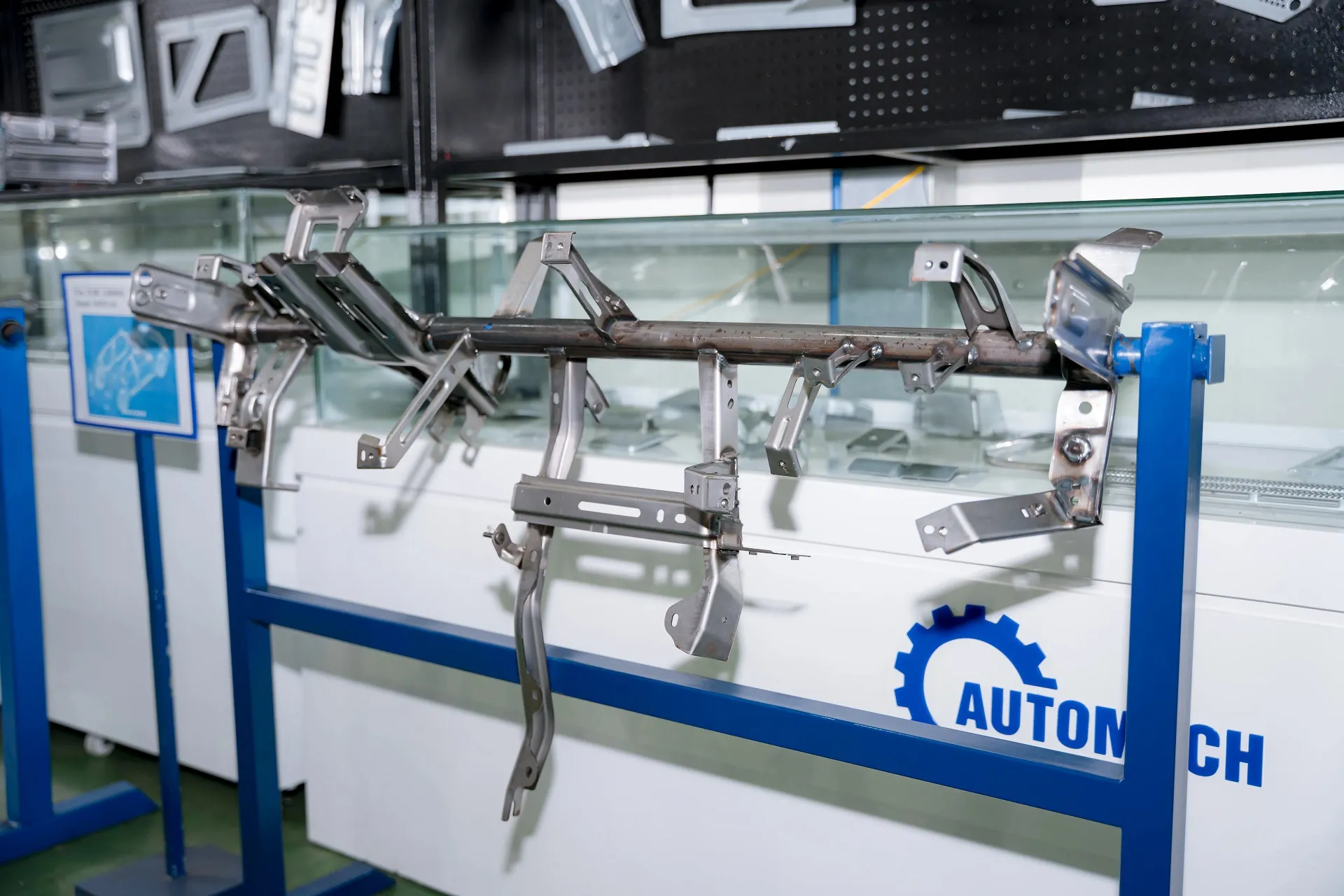
Exhibition Display of Complete Cross Car Beam (CCB) Assembly at Automech Showroom
4. Cross Member vs Cross Car Beam vs B Pillar
4.1 Cross Member vs Cross Car Beam
4.1.1 Structural role
- Cross Member: Located underneath the chassis frame or floor pan, its primary mechanical purpose is carrying heavy powertrain/suspension loads and managing chassis flex.
- Cross Car Beam: Located inside the upper cabin behind the dashboard, its primary purpose is occupant side-impact protection, steering column stabilization, and interior IP module integration.
4.1.2 Location and application
Cross members operate in harsh underbody environments exposed to road debris, mud, and water, requiring heavy-gauge steel and anti-corrosion coatings. CCBs operate inside the clean cabin environment, allowing the use of lightweight thin-wall High-Strength Steel (HSS), aluminum extrusions, or hybrid metal-plastic composite structures.
4.2 Cross Member vs B Pillar
4.2.1 Role of the B pillar in vehicle body structure
The B-pillar is a critical vertical structural column located between the front and rear side doors. Extending from the bottom rocker panel up to the top roof rail, the B-pillar forms the primary side-structure pillar of the Body-in-White.
4.2.2 Differences in load paths and structural functions
- B-Pillar: Manages vertical loads during vehicle rollover events (roof crush resistance) and absorbs direct lateral side impacts.
- Floor Cross Member: Operates horizontally, connecting the bases of the left and right B-pillars across the floor pan to complete the lower side-impact load loop.
4.3 Cross Car Beam vs Chassis Cross Member
4.3.1 Body structure application
The Cross Car Beam is an upper BIW/interior structural component. It focuses on occupant compartment safety, steering column resonance control, and holding complex dashboard electronics.
4.3.2 Chassis application
Chassis cross members are heavy-duty structural components mounted below the floor line. They are designed to withstand cyclic mechanical fatigue, suspension forces, dynamic braking torque, and heavy payload strains.
4.4 Structural vs Non-Structural Automotive Beams
4.4.1 Load-bearing components
Structural beams (such as CCBs, chassis crossmembers, B-pillars, and bumper impact bars) are crash-relevant components governed by strict federal safety regulations. They require certified materials (AHSS, UHSS), validated weld penetration levels, and formal PPAP Level 3 documentation.
4.4.2 Support and reinforcement components
Non-structural beams are secondary support brackets used purely to position non-load-bearing trim, acoustic insulation, carpet hold-downs, or wiring looms. Failure of a non-structural beam will cause trim rattling, but it will never compromise vehicle handling, steering control, or crash safety.
5. Types of Automotive Cross Members
5.1 Body Cross Members
5.1.1 Floor cross member
Floor cross members are stamped metal channels welded horizontally across the top or bottom of the sheet metal floor pan. They reinforce the flat floor sheet against oil-canning (pop-in flexing) and tie the left and right rocker panels together. Furthermore, floor cross members contain integrated reinforcement plates designed to anchor front seat tracks securely during frontal crashes.
5.1.2 Roof and side structure cross members
Roof cross members (commonly referred to as roof bows) are curved, thin-gauge stamped profiles spanning between the upper roof side rails. They support the outer roof sheet metal against wind flutter and provide essential structural rigidity during vehicle rollover accidents to prevent roof collapse.
5.2 Chassis Cross Members
5.2.1 Front chassis cross member
Positioned under the engine compartment, the front chassis cross member (or front subframe) supports the engine oil pan, radiator lower mounts, power steering rack, and front lower control arms. It absorbs heavy frontal road shocks and maintains precise suspension geometry.
5.2.2 Rear chassis cross member
Located above or below the rear axle line, the rear chassis cross member anchors rear multi-link suspension arms, rear differential gearboxes on AWD/RWD platforms, and rear sway bars. It resists rear suspension torque during hard acceleration and cornering.
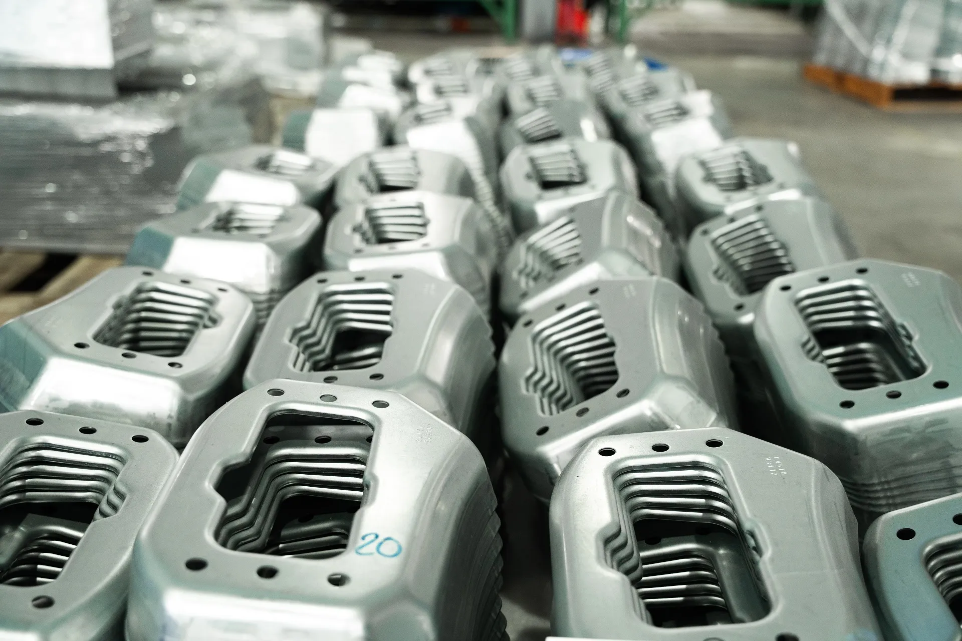
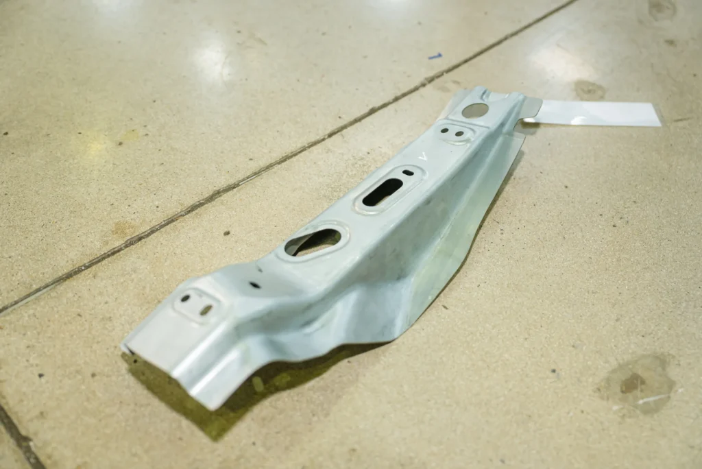
Stacked Precision Stamped Automotive Brackets Ready for Sub-Assembly
5.3 Cross Car Beam Applications
5.3.1 Dashboard cross beam
The standard tubular CCB configuration comprises a central high-strength steel main tube onto which multiple stamped brackets are welded. This configuration is widely deployed across sedan, hatchback, and CUV platforms.
5.3.2 Instrument panel support beam
Heavy-duty CCB architectures engineered for commercial trucks, heavy SUVs, and luxury platforms feature reinforced double-tube or closed box-section designs. These support larger dashboard displays, integrated passenger airbags, and heavy steering column assemblies while meeting strict anti-vibration criteria.
5.4 Cross Member and B Pillar Integration
5.4.1 Structural connection
In modern BIW architecture, the lower floor cross member is aligned directly with the base of the left and right B-pillars. This establishes an uninterrupted transverse structural ring around the middle passenger compartment.
5.4.2 Load transfer between components
When a side impact strikes the outer B-pillar, energy flows vertically down the pillar toward the rocker panel. The floor cross member immediately picks up this lateral force and transfers it across the vehicle floor, distributing crash energy and preventing the B-pillar from intruding into the passenger seating area.
6. Automotive Cross Member Manufacturing Process
[2D / 3D CAD & DFM Review] -> [Stamping & Laser Cutting] -> [Robotic Welding Assembly] -> [Fixture CMM & Quality Inspection]
6.1 Engineering and Product Development
6.1.1 CAD and technical drawings
Every manufacturing workflow begins with deep engineering validation of customer 2D blueprints and 3D native CAD files (.STEP, .IGS). Strict Geometric Dimensioning and Tolerancing (GD&T) callouts establish critical datum planes, hole positioning limits, and surface profile tolerances.
6.1.2 DFM and manufacturing feasibility
Design for Manufacturability (DFM) analysis evaluates die strip layouts, sheet metal stretch ratios, springback tendencies, and robotic welding torch clearances. DFM ensures the part can be mass-produced efficiently without material tearing, micro-cracking, or thermal warping during welding operations.
6.2 Sheet Metal Forming and Stamping
6.2.1 Blanking and piercing
High-speed press lines blank raw steel coils into optimized flat sheet profiles. Piercing operations cut pilot holes and locating slots used to align the part accurately in subsequent forming dies.
6.2.2 Bending and forming
Multi-station progressive dies or transfer press systems execute precise bending, flanging, and deep-drawing operations. Complex die geometries shape the steel, forming stiffening ribs and mounting faces.
6.2.3 Automotive stamping
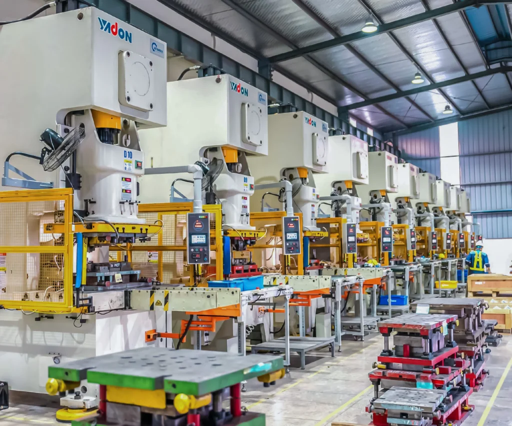
High-tonnage stamping presses (ranging from 400T to 2000T) process structural parts made from High-Strength Steel (HSS) and Advanced High-Strength Steel (AHSS). High press tonnage guarantees clean forming and sharp radii while overcoming material springback.
6.3 Welding and Assembly
6.3.1 Spot welding
Resistance Spot Welding (RSW) is utilized to rapidly tack and join overlapping stamped bracket flanges onto structural tubes or sub-assemblies.
6.3.2 MIG welding
Metal Inert Gas (MIG/MAG) welding provides continuous, deep-penetration fillet welds along structural joints where maximum load transfer and fatigue strength are required.
6.3.3 Laser welding
High-precision laser welding delivers narrow, deeply penetrated weld seams with minimal Heat-Affected Zones (HAZ). Laser welding is increasingly deployed on modern CCB lines to maintain tight geometric tolerances and reduce overall component weight.
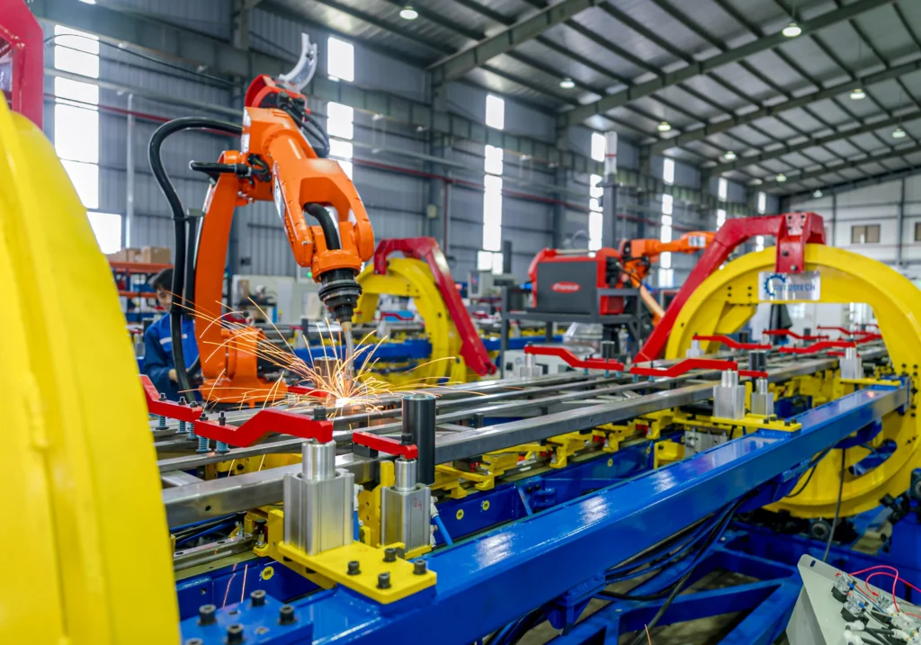
6.3.4 Robotic welding
Automated multi-axis robotic welding cells execute synchronized MIG and spot welds with high precision. Robotics eliminate human error, maintain consistent weld bead profiles, and significantly reduce production cycle times.
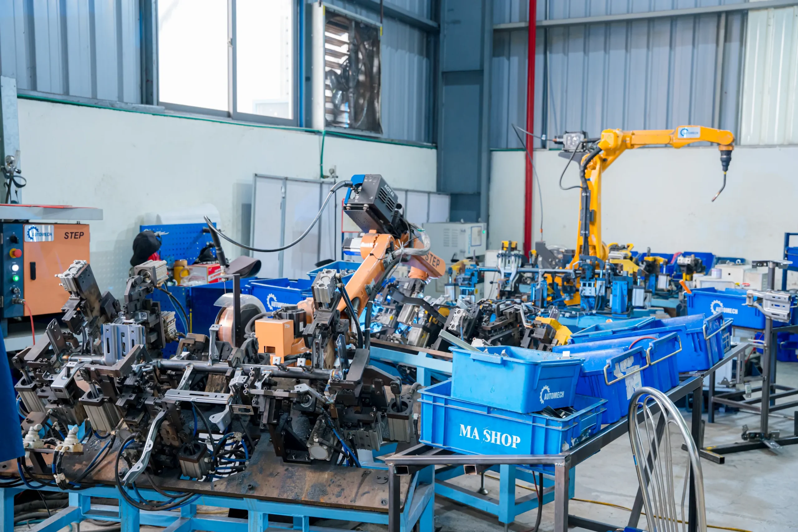
Automated Robotic Welding Cell Workstation with Custom Clamping Fixtures
6.4 Fixture-Controlled Assembly
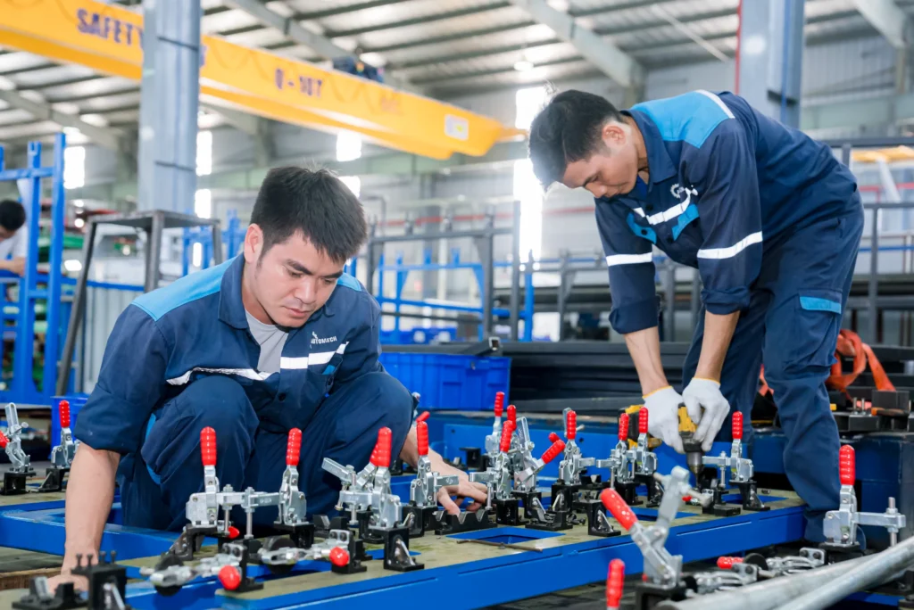
6.4.1 Automotive welding fixtures
Precision pneumatic welding fixtures securely clamp every individual stamped bracket, sleeve, and main tube in exact 3D spatial coordinates before welding torches ignite.
6.4.2 Dimensional positioning and repeatability
Heavy-duty welding fixtures resist thermal expansion caused by welding heat. This guarantees that every finished cross member maintains high dimensional repeatability across high-volume production runs.
6.5 Prototype to Mass Production
6.5.1 Prototype production
Soft-tooling dies and 5-axis laser cutting machines fabricate prototype samples for early physical fitment, crash testing, and NVH validation.
6.5.2 Low-volume production
Pilot production runs test production tooling under real factory conditions, fine-tunes robotic weld parameters, and establishes initial process capability indices (Cpk >= 1.67).
6.5.3 Mass production
Upon receiving formal PPAP Level 3 sign-off, full SOP (Start of Production) deployment ramps up automated press lines and robotic assembly cells for serial mass production.
7. Materials, Design and Performance Requirements
7.1 Materials Used for Automotive Cross Members
7.1.1 Mild steel
Mild steel grades (such as DD11 or DC01) offer high ductility and excellent formability. They are typically reserved for non-crash-relevant secondary mounting brackets and cable harness clips.
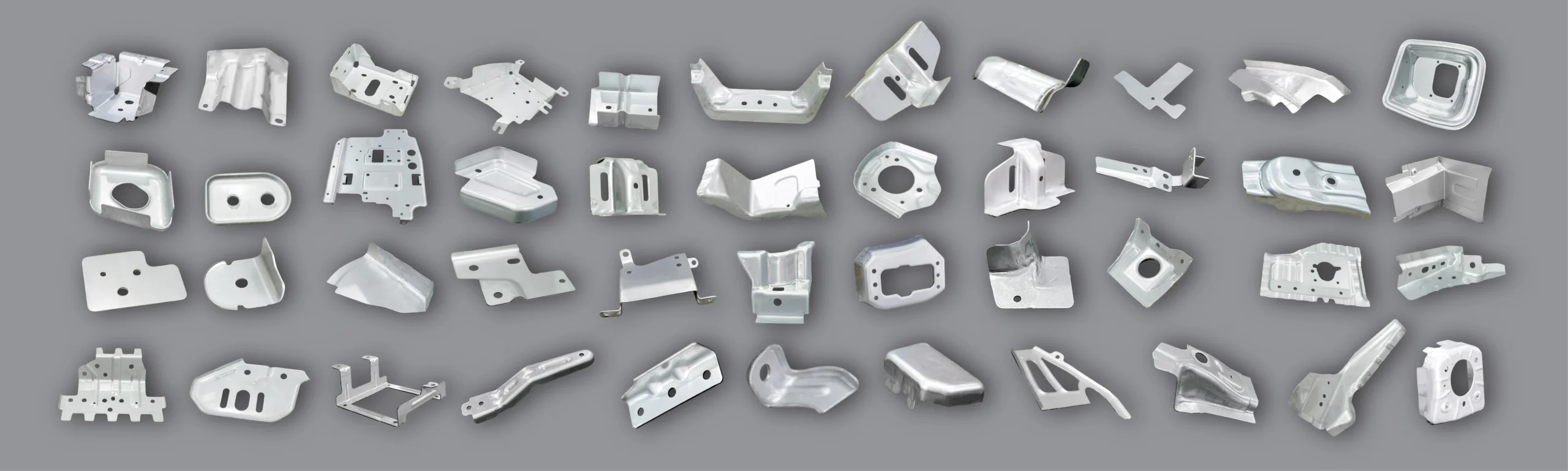
Comprehensive Range of Stamped Sheet Metal Components and Brackets for Automotive Applications
7.1.2 High-strength steel (HSS)
High-Strength Low-Alloy (HSLA) steels deliver higher yield strength, allowing engineers to reduce sheet metal thickness while maintaining overall structural load capacity.
7.1.3 Advanced high-strength steel (AHSS) / Ultra-High-Strength Steel (UHSS)
AHSS grades (such as Dual-Phase DP600/DP800 and Martensitic steels) are widely used for safety-critical CCBs and crash-relevant cross members. These advanced alloys offer extreme tensile strength, maximizing energy absorption during side impacts without adding unnecessary vehicle mass.
7.2 Cross Member Design Requirements
7.2.1 Structural rigidity
Cross members must meet strict static and dynamic stiffness targets. They must resist bending moments and torsional twisting forces without undergoing permanent plastic deformation during aggressive driving maneuvers.
7.2.2 Weight optimization
Through lightweighting strategies—such as variable wall thickness tubes, tailored blanks, and topology optimization—engineers optimize material distribution to meet global vehicle mass reduction goals.
7.2.3 Crash load management
Cross members are engineered with controlled collapse zones. During severe impacts, the component buckles in a predictable sequence to absorb kinetic energy and direct crash forces away from passenger seating areas.
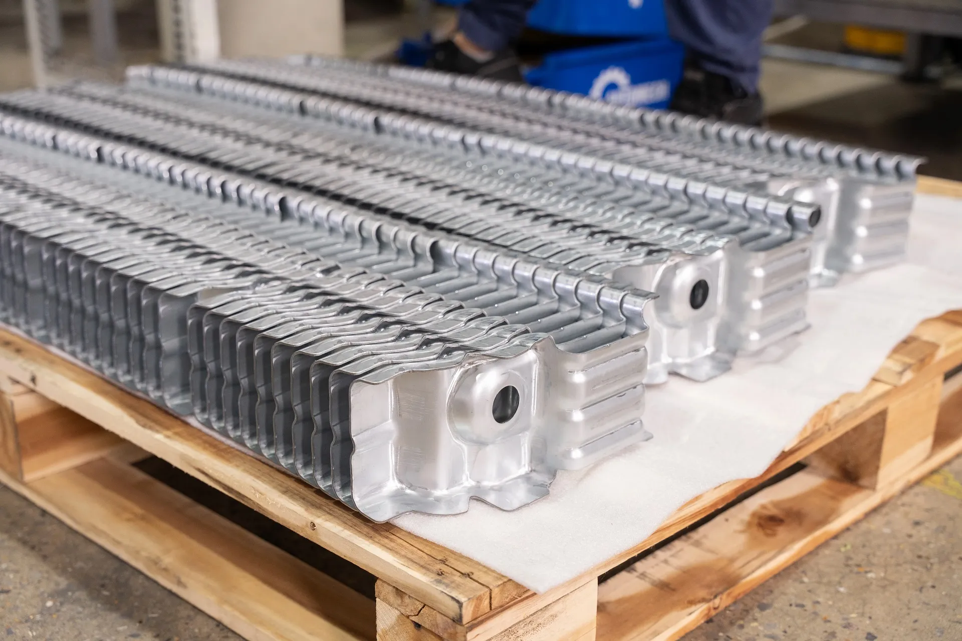
Palletized High-Precision Stamped Metal Components for Vehicle Body Structure
7.3 NVH and Dimensional Requirements
7.3.1 Vibration and noise considerations
Cross car beams must maintain high natural resonant frequencies (typically > 35 Hz). This prevents engine idle vibrations and road shocks from resonating through the steering column and dashboard displays.
7.3.2 Dimensional tolerance
Key mounting interfaces on cross members require tight tolerances (often +-0.5 mm or tighter). This ensures seamless integration with adjacent BIW structures and cockpit modules during final assembly.
7.3.3 Assembly interfaces
Precise hole locations, welded clinch nuts, and locating pins must align perfectly with downstream mating parts to prevent line-stoppages on the main assembly line.
8. Cross Car Beam Stamping, Welding and Assembly
| Manufacturing Stage | Core Process Description | Primary Quality Metric |
| Stamping & Tube Forming | Blanking, CNC tube bending, 5-axis laser profiling, bracket forming | Profile accuracy, zero micro-cracking, springback control |
| Robotic Welding | Multi-axis robotic MIG/Spot welding with pneumatic fixtures | 100% Weld penetration, zero spatter, minimal distortion |
| Surface Treatment | Multi-stage chemical wash and Cathodic Electrodeposition (ED) coating | Coating film thickness, salt spray corrosion resistance |
| Dimensional QA | 100% Checking fixture verification & CMM metrology scanning | Full GD&T position tolerances, process capability Cpk >= 1.67 |
8.1 Cross Car Beam Stamping
8.1.1 Sheet metal forming requirements
Forming intricate CCB brackets from high-strength steel requires precise springback compensation in press dies. Advanced CAD surface morphing compensates for metal springback, ensuring final stamped parts match theoretical CAD dimensions.
8.1.2 Stamping die requirements
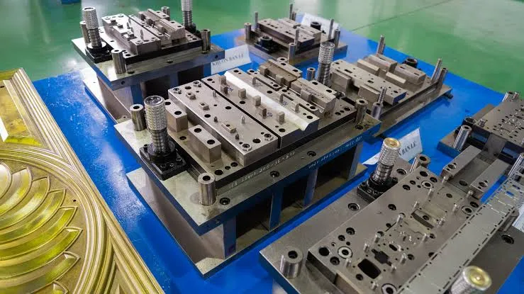
Heavy-duty progressive and transfer dies constructed from premium hardened tool steels (SKD11, DC53, or D2) are essential. Vacuum heat treatment ensures die components endure hundreds of thousands of press strokes without chipping or dimensional wear.
8.2 Cross Car Beam Welding Assembly
8.2.1 Welding sequence
Weld paths and sequences are strategically programmed across robotic cells. Balancing thermal input prevents thermal warping and ensures the main CCB tube remains straight after welding.
8.2.2 Robotic welding integration
Multi-robot assembly cells perform simultaneous spot welding and continuous MIG seam welding. Real-time sensors track arc voltage, current, and wire feed speeds to prevent weld porosity or insufficient penetration.
8.2.3 Fixture-controlled welding
Custom-engineered pneumatic welding fixtures clamp all individual brackets tightly against heavy-duty locating pins. Fixture sensors verify part presence before robotic torches initiate welding.
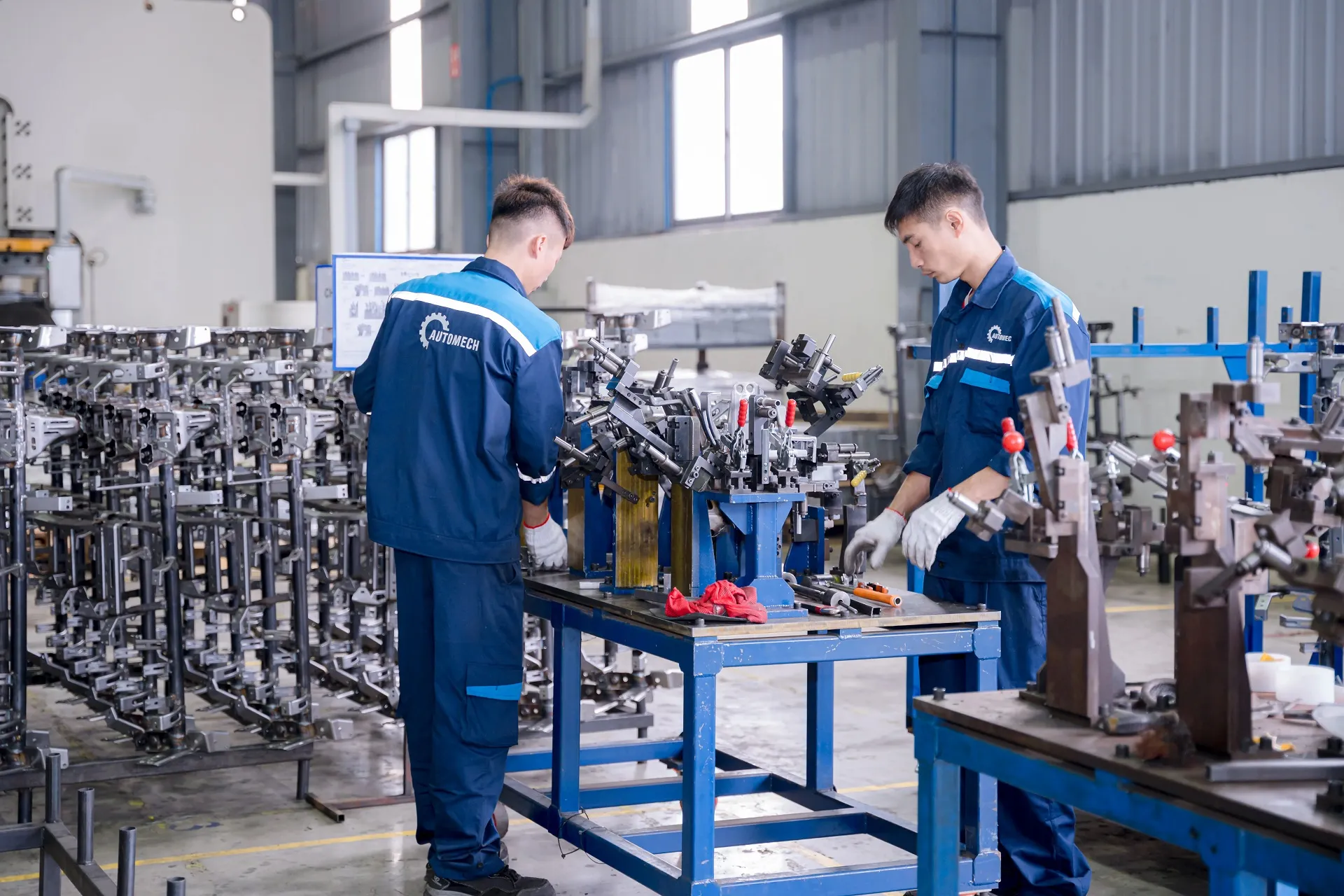
Technicians Assembling Welding Fixtures for Automotive Cross Car Beam Production Line
8.3 Cross Car Beam OEM Manufacturing
8.3.1 OEM technical specifications
Cross car beam suppliers must strictly adhere to comprehensive OEM technical delivery specifications. This includes meeting rigorous destructive weld testing standards, salt spray anti-corrosion limits, and total dimensional stability.
8.3.2 Tier 1 and Tier 2 production requirements
As specialized Tier 2 or Tier 1 suppliers, CCB manufacturers deliver complete welded structural assemblies directly to cockpit integration facilities on strict Just-in-Time (JIT) schedules.
8.4 Manufacturing Process Integration
8.4.1 Stamping to welding
Automated material handling systems and robotic transfers shift stamped brackets directly into welding cells, preventing manual handling damage and part contamination.
8.4.2 Welding to dimensional inspection
Upon exiting the welding cell, completed CCB assemblies pass into automated checking fixtures or inline optical vision stations to instantly verify weld nut presence and critical mounting hole coordinates.
8.4.3 Assembly and export packaging
Finished CCB assemblies undergo Cathodic Electrodeposition (ED coating) for long-term rust prevention. Assemblies are packed into custom returnable steel racks with soft dunnage separators to ensure damage-free transit during international shipping.
9. Quality Control for Automotive Structural Components
9.1 Dimensional Quality Control
9.1.1 CMM inspection
Climate-controlled Metrology Labs equipped with high-precision 3D Coordinate Measuring Machines (CMM) perform full geometric audits on production batch samples, validating spatial coordinates against original CAD models.
9.1.2 Gauge inspection
Dedicated shop-floor checking fixtures provide rapid 100% verification. Operators use custom physical GO/NO-GO gauges to confirm hole positions, bracket locations, and overall spatial alignment.
9.1.3 Optical measurement
3D blue-light optical laser scanners capture full-field surface color-map deviations. This allows engineers to detect subtle panel distortion, metal springback, or die wear across the entire assembly.
9.2 Welding Quality Control
9.2.1 Weld consistency
Robotic weld controllers continuously log welding current, arc voltage, and gas flow rates for every single weld seam, ensuring uniform quality.
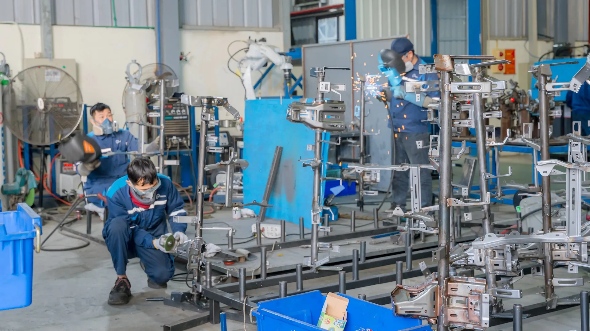
Skilled Welders and Technicians Executing Manual Finishing and Quality Assembly of CCB Structures
9.2.2 Weld position and penetration
Periodic destructive chisel testing and metallurgical cut-and-polish cross-sectioning are conducted to verify internal weld nugget size, throat thickness, and penetration depth.
9.2.3 Robotic welding monitoring
Smart factory vision systems inspect weld seams post-welding to automatically detect surface defects such as weld spatter, pinholes, or arc burn.
9.3 Automotive Quality Requirements
9.3.1 First Article Inspection (FAI)
Before signing off on serial production runs, a complete First Article Inspection (FAI) validates every dimension, material certificate, and weld test result.
9.3.2 In-process inspection
Statistical Process Control (SPC) charts track critical product characteristics in real time. Process capability indices (Cp, Cpk >= 1.67) ensure production stability across shifts.
9.3.3 Traceability
Laser-etched QR codes or dot-peen matrix stamps are applied to finished assemblies, linking every part back to its raw material coil lot, press run, robotic weld station, and inspection operator log.
9.4 Quality Documentation
9.4.1 Inspection reports
Comprehensive CMM dimension measurement logs and material test reports accompany every batch shipment.
9.4.2 Process control records
Archived SPC control charts, heat-treatment logs, and Cathodic ED coating thickness test results ensure complete process accountability.
9.4.3 OEM quality documentation
Full PPAP (Production Part Approval Process) Level 3 documentation packages—including APQP frameworks, PFMEA analysis, Control Plans, and Gage R&R studies—are maintained for OEM review.
10. How to Choose a Cross Car Beam Manufacturer
10.1 Manufacturing Capability
10.1.1 Automotive stamping capability
Verify that the supplier operates high-tonnage press lines capable of processing high-strength structural steels with complex progressive and transfer tooling.
10.1.2 Welding and assembly capability
Ensure the facility deploys automated robotic welding cells (MIG/Spot/Laser) supported by pneumatic clamping fixtures to maintain high production repeatability.
10.1.3 Fixture and tooling capability
In-house tool design, build, and maintenance capabilities enable fast tool modification, engineering change order (ECO) implementation, and routine preventive maintenance.
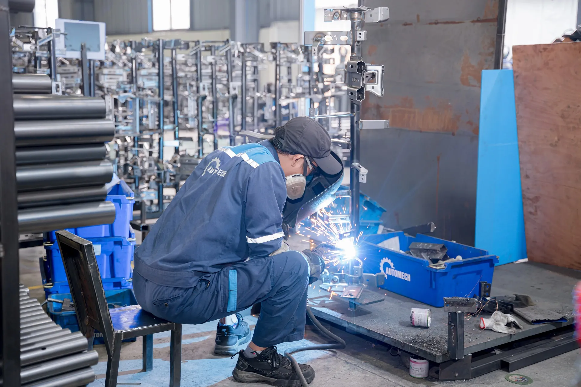
Technician Performing Manual Spot and Arc Welding on Automotive CCB Brackets
10.2 Engineering Capability
10.2.1 CAD and DFM support
Select an experienced supplier offering Early Supplier Involvement (ESI) and DFM reviews to help optimize part geometry, improve material yield, and reduce tooling costs.
10.2.2 Manufacturing feasibility review
A thorough pre-bidding feasibility review prevents unexpected manufacturing bottlenecks, material cracking issues, or weld distortion problems down the line.
10.2.3 Prototype to mass production support
Look for a partner capable of guiding a project seamlessly through soft-tool prototyping, pre-production pilot runs, PPAP approval, and full mass production.
10.3 Supplier Quality and Compliance
10.3.1 Quality management systems
An active IATF 16949 certification audited by accredited third-party registration bodies is mandatory for automotive structural component manufacturing.
10.3.2 Dimensional inspection capability
In-house climate-controlled metrology laboratories equipped with 3D CMMs and custom physical checking fixtures are essential for verifying complex GD&T parameters.
10.3.3 Automotive OEM and Tier supplier experience
A proven track record supplying structural components to international automotive supply chains demonstrates robust operational maturity.
10.4 Cross Car Beam Supplier Vietnam
10.4.1 Export manufacturing capability
Vietnam has established itself as a competitive manufacturing hub for high-precision automotive structural components, combining technical expertise with competitive labor and conversion costs.
10.4.2 US and European market requirements
Vietnamese OEM exporters operate under modern international trade frameworks, offering duty advantages and crucial supply chain resilience (China+1 strategy) for global Tier 1 buyers.
10.4.3 Supplier communication and project management
Dedicated APQP project management teams providing clear, regular milestone reporting in fluent English ensure smooth project execution.
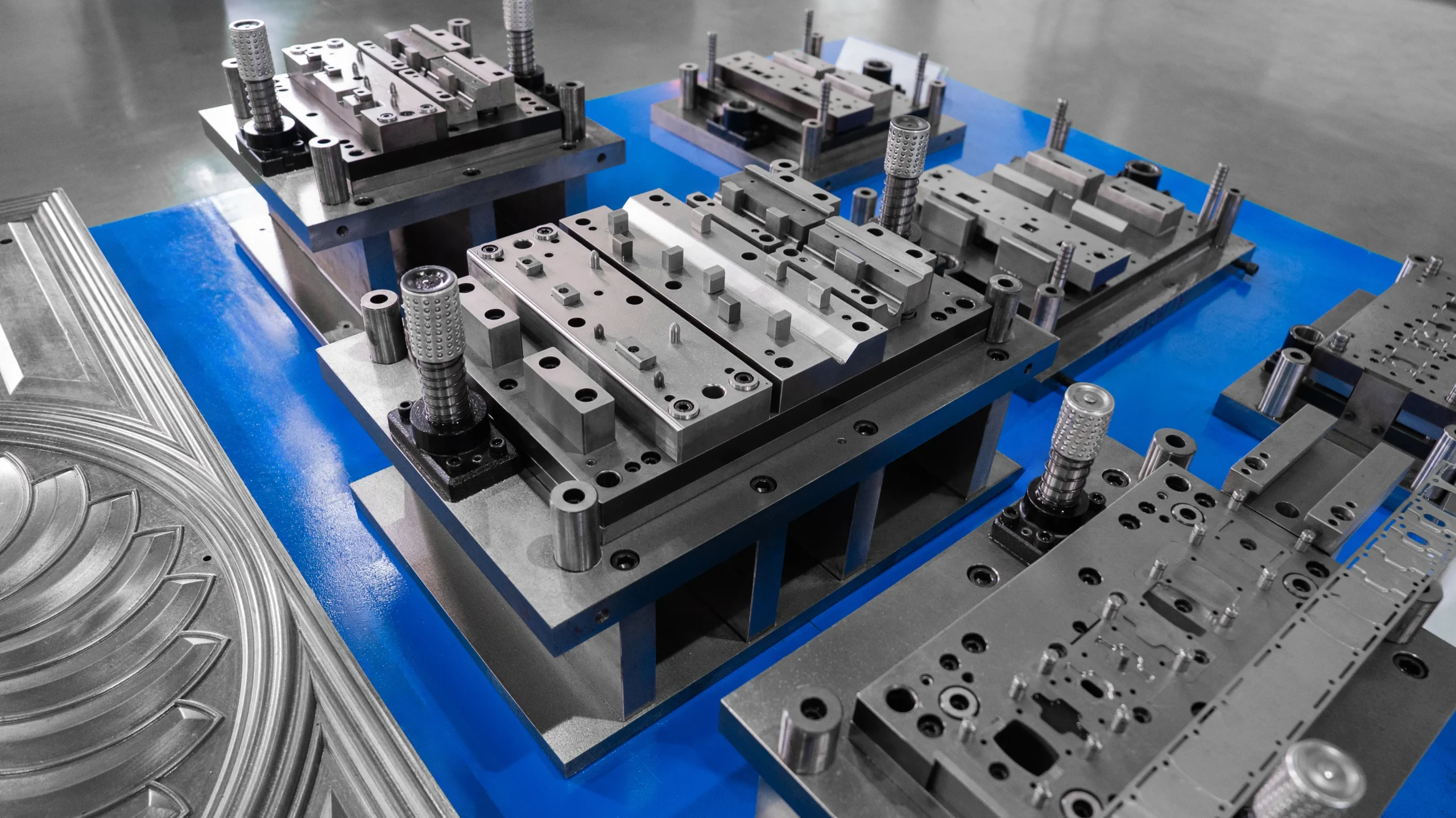
High-Precision Stamping Die Sets and Tooling Assemblies for Automotive Sheet Metal Parts
11. Cross Car Beam Manufacturer in Vietnam – Automech
11.1 Automotive Structural Component Manufacturing
Automech is a premier automotive contract manufacturer in Vietnam, specializing in high-precision structural BIW components, chassis cross members, and cockpit cross car beams for global OEMs and Tier 1 automotive suppliers.
11.1.1 Cross car beam manufacturing capability
Automech delivers end-to-end manufacturing solutions for complex tubular and stamped CCB assemblies, engineered to meet strict crash safety and NVH performance standards.
11.1.2 Automotive cross member manufacturing
Our facility operates high-capacity press lines and automated assembly cells designed to process mild steel, High-Strength Steel (HSS), and Advanced High-Strength Steel (AHSS) cross members.
11.1.3 OEM and Tier 1/Tier 2 support
We offer flexible production models accommodating high-volume serial production as well as specialized low-volume vehicle platform runs.
11.2 Stamping, Welding and Assembly Capabilities
11.2.1 Automotive metal stamping
Equipped with over 100 industrial presses and automated coil feed lines, Automech handles high-precision stamping and progressive die forming for structural automotive parts.
11.2.2 Robotic welding
Synchronized 6-axis robotic welding cells perform precise spot, projection, and continuous MIG welding operations.
11.2.3 Fixture-controlled assembly
Custom-engineered pneumatic assembly fixtures ensure exact dimensional alignment and repeatability across all welded assemblies.
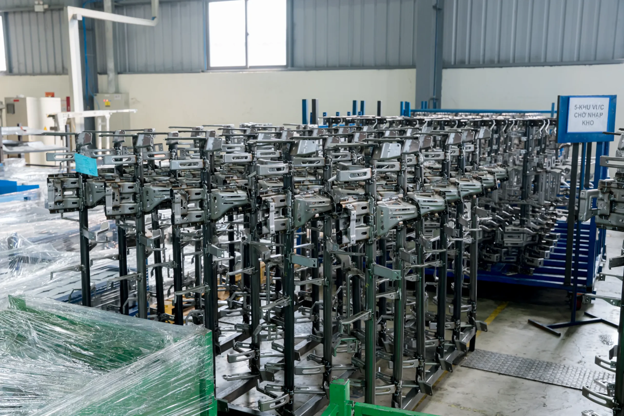
Staging Area for Finished Cross Car Beam Assemblies Awaiting Final Quality Inspection & Storage
11.3 Engineering and Quality Support
11.3.1 CAD and DFM review
Our engineering team conducts thorough DFM analyses and die springback simulations, optimizing part geometry and tool life prior to production.
11.3.2 Dimensional inspection
Operating under IATF 16949 quality systems, Automech utilizes 3D CMM metrology, optical laser scanning, and custom physical checking fixtures to guarantee 100% quality compliance.
11.3.3 Prototype to mass production
Structured APQP project management ensures smooth progression from initial soft-tool prototyping and pilot runs through to formal PPAP Level 3 approval and mass production launch.
11.4 Automotive Export Manufacturing
11.4.1 Cross car beam supplier Vietnam
Strategically located near major deep-water ports in Vietnam, Automech offers efficient maritime shipping access to North American, European, and Asian markets.
11.4.2 US and European market support
We adhere to international export packaging standards (including VCI rust inhibition and heavy-duty steel dunnage racks) to ensure components arrive in pristine condition.
11.4.3 RFQ and technical quotation process
Our engineering sales team provides transparent cost-breakdown models and technical proposals within 48 to 72 hours.
11.5 Request a Cross Car Beam RFQ
Partner with Automech for your next automotive structural component project.
11.5.1 Upload technical drawings and CAD files
Submit your 2D blueprints (with GD&T callouts) and native 3D CAD files (.STEP / .IGS).
11.5.2 Request manufacturing feasibility review
Our engineering staff will execute a complimentary DFM analysis and manufacturing feasibility assessment.
11.5.3 Request cross car beam quotation
Receive a detailed quotation covering tooling development, unit piece price, and complete PPAP project timelines.
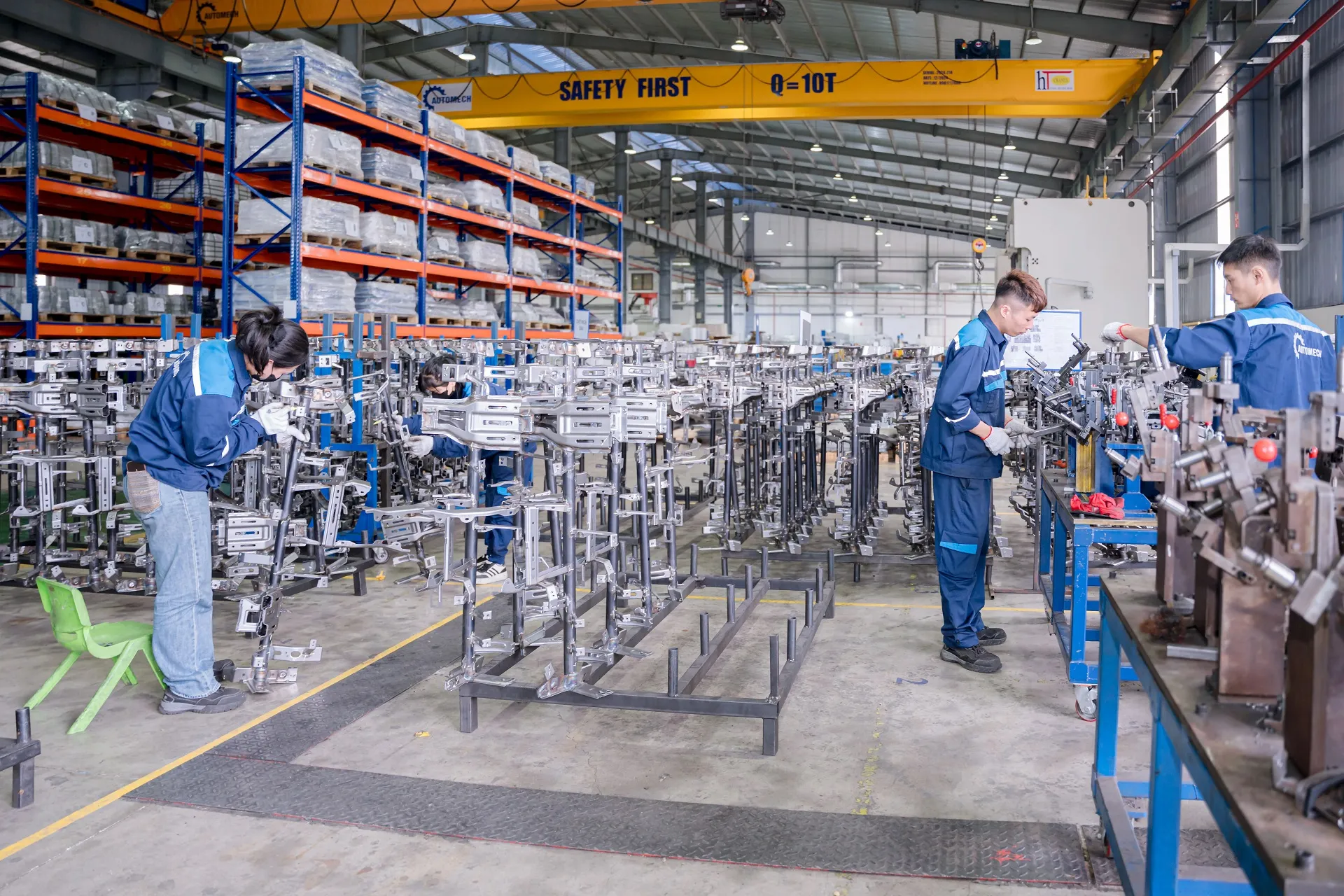
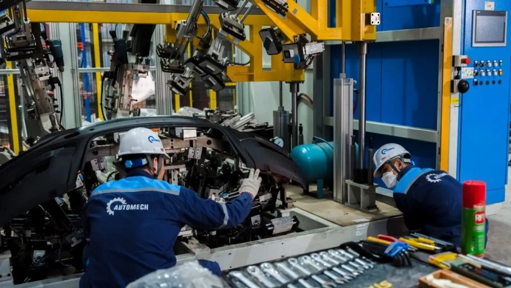
Overview of Assembly and Inspection Workshop for Automotive Structural Assemblies
12. FAQ About Car Cross, Cross Members and Cross Car Beams
12.1 What does “car cross” mean?
12.1.1 Common interpretations of the search term
“Car cross” is a common search typographical error for “car cross member” or “cross car beam”, which are transverse structural reinforcement components used in chassis and cockpit assemblies.
12.2 What is a cross member on a car?
12.2.1 Main structural functions
A cross member is a transverse structural steel beam mounted across the frame or floor pan to improve torsional rigidity, carry powertrain loads, and distribute crash energy.
12.3 What is a crossmember of a car?
12.3.1 Cross member terminology
“Crossmember” is simply the single-word spelling variation of “cross member”. Both terms describe identical structural components.
12.4 What is a cross car beam?
12.4.1 Dashboard and instrument panel applications
A cross car beam (CCB) is an interior cabin structural assembly mounted between the front A-pillars behind the dashboard. It supports the steering column, airbags, and HVAC while absorbing side-impact crash energy.
12.5 What does a cross member do on a car?
12.5.1 Rigidity and load distribution
It prevents chassis twisting, preserves dynamic suspension geometry, and distributes localized impact forces evenly across the vehicle frame.
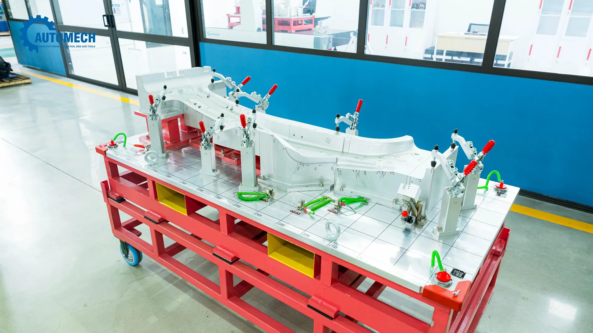
Custom Checking Fixture (CMM / Inspection Gauge) for Automotive Structural Components Quality Control
12.6 Where is a cross car beam located?
12.6.1 Position within the vehicle body
It is mounted transversely inside the front cabin area, spanning directly between the left and right cowl side inner panels (A-pillars) under the windshield cowl.
12.7 What is the difference between a cross member and a B pillar?
12.7.1 Structural function comparison
A cross member extends horizontally across the floor pan or chassis, whereas a B-pillar stands vertically between the front and rear side doors.
12.8 How are automotive cross members manufactured?
12.8.1 Stamping, welding and assembly
They are manufactured by stamping high-strength sheet metal, bending structural tubes, and joining components using multi-axis robotic welding cells inside pneumatic assembly fixtures.
12.9 What materials are used for automotive cross members?
12.9.1 Steel and high-strength steel
They are typically produced using High-Strength Low-Alloy steel (HSLA), Advanced High-Strength Steel (AHSS), structural aluminum extrusions, or hybrid metal-plastic pressings.
12.10 How do I choose a cross car beam manufacturer?
12.10.1 Engineering, quality and production criteria
Key criteria include active IATF 16949 certification, in-house DFM engineering capability, high-tonnage press capacity, automated robotic welding cells, and 3D CMM metrology verification.
Automech Mechanical Equipment and Solutions Joint Stock Company
Head Office: No. 285 Phuc Loi Street, Phuc Loi Ward, Hanoi City
Da Nang Branch: No. 20 Nguyen Sinh Sac Street, Hoa Khanh Ward, Da Nang City
Ho Chi Minh Branch: No. 84, Street No. 10, Van Phuc Urban Area, Hiep Binh Ward, Ho Chi Minh City
Factory No. 1: Automech Automation Equipment, Mold & Tool Manufacturing Factory – Automech Demo Center: Dinh Tram Industrial Park, Nenh Ward, Bac Ninh City, Vietnam
Factory No. 2: Automech Parts Manufacturing & Component Fabrication Factory: Viet Nhat Industrial Cluster, Xuan Cam Commune, Bac Ninh City, Vietnam
Hotline: 0902 997 331
Website: https://automechmfg.com/
Fanpage: https://www.facebook.com/automech.mfg/
YouTube: https://www.youtube.com/@Automechmfg