As global automotive OEMs and Tier-1 suppliers navigate increasingly complex supply chain dynamics, securing precision-engineered structural components becomes vital. Cross car beams serve as the critical backbone of instrument panel assemblies, demanding high structural integrity, exact geometric tolerances, and strict safety compliance. Automech provides end-to-end OEM manufacturing solutions for cross car beams – combining advanced progressive stamping, high-precision tooling, and IATF 16949-certified quality management from Vietnam.

Complete Cross Car Beam (CCB) assembly with custom mounting brackets on display stand
1. Cross car beam OEM manufacturer: engineering solutions for automotive OEMs
In the precision structural engineering of modern vehicles, cabin safety and driving stability rely heavily on the hidden backbone beneath the dashboard. Partnering with a reliable cross car beam OEM manufacturer is the ultimate key for automotive OEMs to optimize production costs while meeting stringent structural safety standards.
1.1 What is a cross car beam OEM manufacturer?
1.1.1 Definition of a cross car beam OEM manufacturer
An Original Equipment Manufacturer (OEM) for cross car beams (CCB) is a specialized cross car beam OEM manufacturer responsible for fabricating, stamping, welding, and assembling the complex metal structure that connects the vehicle’s A-pillars according to the exact technical drawings and strict quality criteria of automotive brands.
1.1.2 OEM manufacturing vs contract manufacturing
The core difference between these two business models lies in engineering capability and technical accountability:
- Design capability: An OEM manufacturer handles co-engineering, Design for Manufacturability (DFM) optimization, and advanced in-house tooling development, whereas a contract manufacturer operates strictly as a job shop, producing parts based solely on provided samples with zero engineering intervention.
- Quality tools: OEM production mandates the strict implementation of automotive core tools (APQP, PPAP, FMEA, SPC), while contract manufacturing only covers basic final-gate inspections without deep supply chain integration.
- Risk & liability: An OEM manufacturer carries full accountability for structural durability, crashworthiness, and system integration, while a contract manufacturer’s responsibility is limited to individual dimensional tolerances.

Front entrance facade and company signboards of Automech Parts manufacturing factory
1.1.3 Responsibilities in the automotive supply chain
Within the automotive supply chain, a cross car beam OEM manufacturer serves as a vital backbone. Their responsibilities span from raw steel coil sourcing and leveler feeding to automated progressive die stamping, robotic welding assembly, anti-corrosion surface treatment, and final logistical compliance.
1.1.4 Serving OEMs, Tier 1 and Tier 2 suppliers
A CCB OEM manufacturer supplies structural components directly to major automakers (OEMs) and serves as a vital strategic partner for Tier 1 suppliers (who assemble complete cockpit and dashboard modules) and Tier 2 component suppliers who provide smaller metal stampings.
1.2 What is a cross car beam?
1.2.1 Cross car beam definition
A cross car beam (CCB) is a heavy-duty structural assembly composed of main tubes, stamped brackets, and steering column supports, spanning the entire width of the vehicle cabin right behind the dashboard instrument panel.
1.2.2 Main functions in vehicle architecture
This crucial component defines the geometry of the front cockpit, distributes structural loads across the front chassis, and provides a rigid mounting foundation for a vast array of electronic and mechanical interior systems.
1.2.3 Relationship with dashboard module and BIW
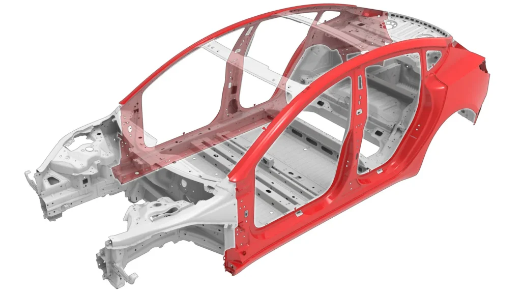
The CCB acts as the structural bridge that integrates the complete dashboard module into the Body in White (BIW) shell. The dimensional precision of the CCB determines how perfectly the interior cockpit fits into the raw vehicle frame.
1.2.4 Common vehicle applications
From compact city hatchbacks and intelligent Electric Vehicles (EVs) to heavy-duty pickup trucks and multi-purpose vehicles (MPVs), every platform requires a highly customized cross car beam engineered for its specific layout.

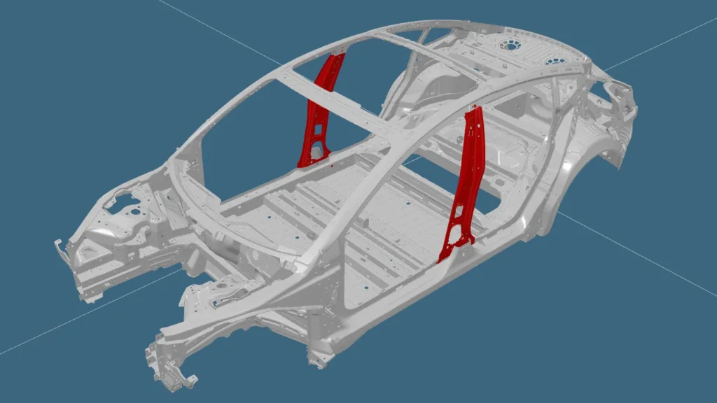
3D CAD rendering isometric view of an automotive Cross Car Beam structure
1.3 Role of cross car beam in automotive body structure
1.3.1 Structural load distribution
During vehicle operation or when navigating uneven terrain, the CCB absorbs and distributes torsional loads across the chassis, preventing localized structural deformation of the front cabin area.
1.3.2 Steering column and dashboard support
The heavy weight of the steering column, passenger airbag module, climate control system (HVAC), and digital infotainment displays all rest on this single beam. Any compromise in structural rigidity will trigger persistent steering wheel vibration.
1.3.3 Occupant safety and crash energy management
In frontal crashes or side-impact collisions, the CCB acts as a robust energy-absorbing barrier. It manages crash kinetic energy to prevent cabin intrusion, directly protecting the lives of the driver and front passenger.
1.3.4 NVH (noise, vibration & harshness) performance
A rock-solid cross car beam assembly with precise joint welds engineered by a premium cross car beam OEM manufacturer effectively dampens natural frequencies transmitted from the engine and road. This drastically isolates cabin noise and harsh vibrations, ensuring a smooth ride.
2. Cross car beam manufacturing process
Manufacturing a cross car beam at an automated factory requires a synchronized flow across highly specialized production cells.
[OEM Drawing] ➔ [DFM Analysis] ➔ [Progressive/Transfer Stamping] ➔ [Robotic Welding] ➔ [ED Coating] ➔ [CMM Verification]

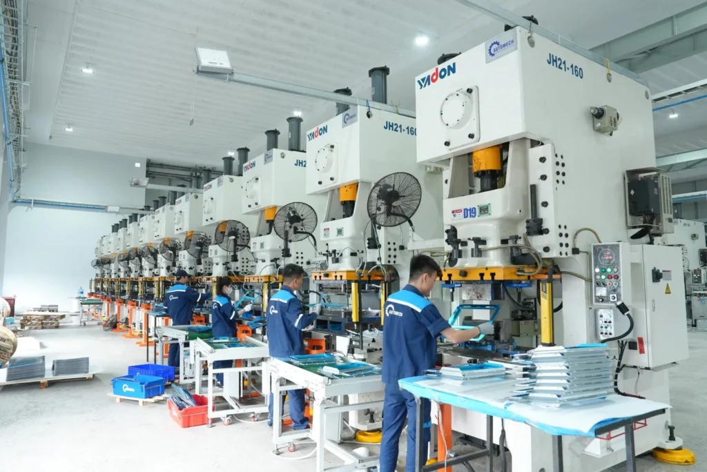
High-capacity metal stamping workshop line with technicians operating hydraulic presses
2.1 Engineering design & DFM
2.1.1 OEM drawing review
Every project begins with an exhaustive appraisal of the customer’s 2D engineering blueprints and 3D CAD models to detect potential geometric interferences early on.
2.1.2 CAD/CAM & GD&T requirements
Utilizing advanced CAD/CAM software to simulate mechanical stress while strictly enforcing Geometric Dimensioning and Tolerancing (GD&T) ensures critical locating points remain accurate to within tight tolerances.
2.1.3 Design for manufacturability (DFM)
DFM analysis optimizes die strip layouts, sheet metal bend radii, and robotic welding accessibility. This guarantees smooth mass production and avoids material tearing or thermal warping during welding.
2.1.4 Prototype validation
Before investing in expensive permanent hard tooling, soft-tool prototypes are fabricated to validate physical mechanical properties and run simulated crash tests.
2.2 Material selection
2.2.1 High strength steel (HSS)
High strength steel (HSS) is widely selected for brackets and structural braces to deliver excellent yield strength while maintaining the cold-forming ductility needed for stamping.
2.2.2 Advanced high strength steel (AHSS)
For next-generation vehicle platforms, advanced high strength steel (AHSS) is utilized. This allows engineers to thin the tube walls to minimize vehicle weight while significantly increasing the tensile strength and moment of inertia.
2.2.3 Material thickness selection
Depending on the load-bearing requirements of individual mounting brackets and the main structural tube, the raw sheet metal thickness typically ranges from 1.2mm to 2.5mm.
2.2.4 Corrosion protection & surface treatment
Incoming steel coils must possess strict metallurgical certifications and clean surfaces, fully prepped for advanced post-production anti-oxidation chemical coatings.

Clean, spacious assembly and packing floor for finished stamped sheet metal parts
2.3 Cross car beam stamping process
2.3.1 Coil feeding
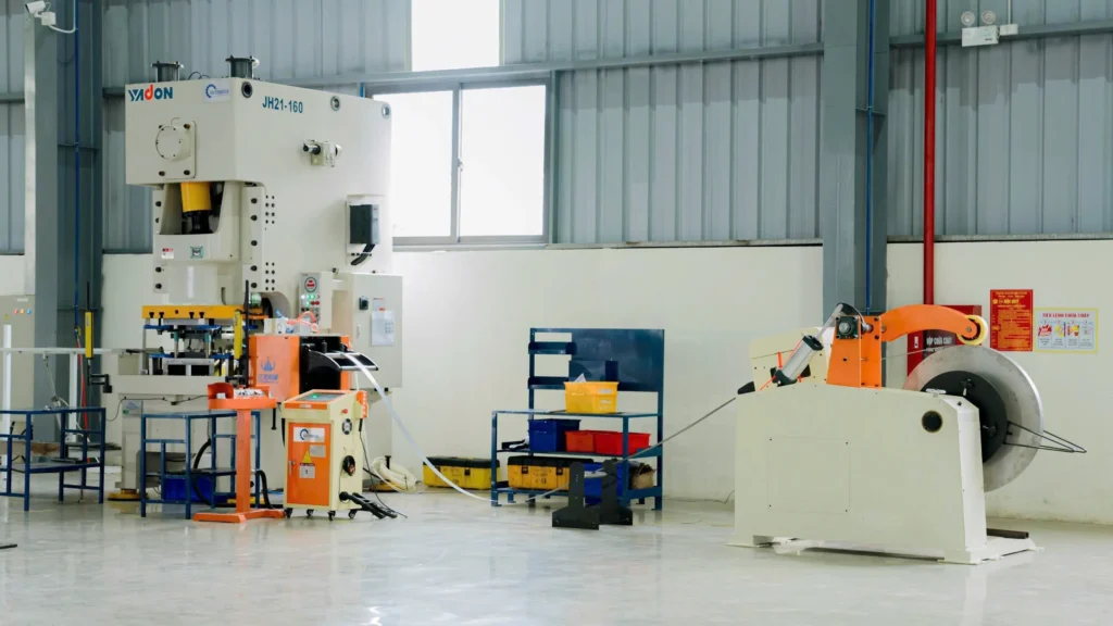
Raw steel coils are uncoiled and fed through an automated straightener-leveler system to eliminate internal material coil set before entering the press line.
2.3.2 Progressive die stamping
Progressive die tooling is ideal for high-volume, small-to-medium-sized intricate mounting brackets. This continuous process maximizes production throughput and optimizes material utilization.
2.3.3 Transfer die stamping
For large structural components or parts requiring deep-drawn features, multi-station transfer dies coupled with automated robotic arms are deployed to lift and shift parts between press beds.
2.3.4 Press tonnage selection
Heavy-duty mechanical and hydraulic press lines ranging from 400 tons to over 1000 tons are mandatory to accurately form tough AHSS grades without inducing micro-cracks.
2.3.5 Precision forming operations
Trimming, piercing, flanging, and deep drawing are executed in a tightly controlled sequence to completely negate metal springback anomalies.
2.4 Cross car beam welding assembly
2.4.1 Robotic MIG welding
Automated Metal Inert Gas (MIG) welding cells utilizing high-speed robotic arms guarantee deeply penetrated, uniform, and continuous weld seams at high-stress joint interfaces.
2.4.2 Robotic spot welding
Resistance spot welding (RSW) robots are deployed for swift, localized fastening of thin-sheet reinforcement plates onto the main tubular body of the beam.
2.4.3 Laser welding (optional)
For premium lightweight CCB configurations, high-density laser welding technology can be integrated to produce ultra-fine joints with a minimal Heat-Affected Zone (HAZ), eliminating structural distortion.

Robotic welding cell equipped with Plymovent industrial fume extraction system
2.4.4 Welding fixtures & jigs
Pneumatically actuated, high-precision welding jigs with integrated proximity sensors clamp the component parts firmly in place throughout the welding cycle.
2.4.5 Structural assembly process
Sub-assemblies are sequentially welded inside modular cells before being fed into a master robotic cell for final structural integration of the complete cross car beam.
2.5 Surface treatment & final processing
2.5.1 Deburring
An automated deburring process removes all sharp burrs, flash, and weld spatters generated during stamping and welding operations.
2.5.2 Surface cleaning
The welded assemblies pass through an intensive multi-stage chemical wash line to strip away stamping oils, rust, and micro-contaminants.
2.5.3 Anti-corrosion coating
Cathodic Electrodeposition (ED Coating) ensures a uniform paint film penetrates every inner corner and recess of the hollow beam, easily surpassing rigorous automotive salt spray tests.
2.5.4 Final packaging
Finished cross car beams are carefully loaded into customized returnable steel racks fitted with soft dunnage separators to prevent scratches during transit and export shipping.

Panoramic aerial view of Automech Parts manufacturing plant and facility headquarters
3. BIW integration & automotive structural engineering
3.1 Cross car beam within body in white (BIW)
3.1.1 Integration into BIW assembly
On the body in white (BIW) main line, the cross car beam is one of the initial structural sub-systems bolted or spot-welded securely into the raw vehicle skeleton.
3.1.2 Structural alignment
Perfect structural alignment is critical. Even a minor deviation can cause fitment issues when downstream teams try to hang the doors or seal the front windshield glass.
3.1.3 Assembly fixtures
Dedicated heavy-duty framing fixtures anchor the CCB inside the BIW cabin to perfectly synchronize its spatial coordinates with the entire vehicle body.
3.1.4 Dimensional stability
Exceptional dimensional stability eliminates residual welding stresses within the metal, preventing the chassis from warping or shifting over years of real-world driving.

High-precision stamped steel structural reinforcement bracket for Cross Car Beam
3.2 Structural performance requirements
3.2.1 Vehicle rigidity
The CCB contributes directly to the vehicle’s overall torsional rigidity, preventing cabin twist and significantly improving high-speed cornering stability.
3.2.2 Crashworthiness
Crashworthiness indicators are audited through destructive hydraulic crushing tests conducted on representative units selected from production lots to ensure safety compliance.
3.2.3 Durability testing
The structure must survive fatigue testing across millions of high-frequency vibration cycles to simulate a long vehicle operational life cycle under real-world conditions.
3.2.4 Fatigue performance
Fatigue performance engineering ensures that the welded joints and bracket connections do not develop micro-fractures under continuous cyclic loads over time.

Precision stamped sheet metal bracket with mounting holes for automotive structural frame
3.3 NVH engineering considerations
3.3.1 Vibration reduction
By strategically thickening sheet metal and adding reinforcement ribs, a seasoned manufacturer shifts the natural frequency of the CCB away from engine and road idle frequencies, eliminating cabin resonance.
3.3.2 Noise isolation
A stiffened cross car beam supports the firewall, effectively blocking engine bay noise and high-speed wind roar from invading the passenger compartment.
3.3.3 Cabin comfort
Minimizing tactile feedback through the steering column and dashboard structures directly enhances premium cabin comfort and reduces driver fatigue.
3.3.4 Structural optimization
Advanced finite element analysis (FEA) guides the structural optimization process, ensuring the perfect balance between mass reduction and acoustic isolation.
4. Automotive manufacturing technologies
4.1 Progressive die tooling
4.1.1 Progressive die design
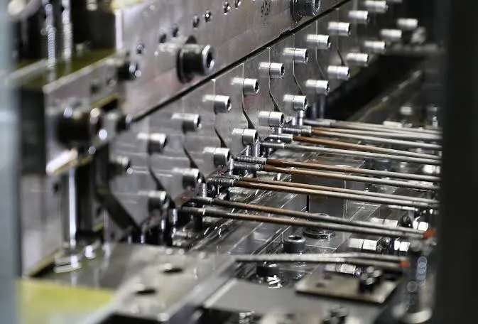
Designing progressive die systems demands advanced tools and dies engineering. Each automated station carries out a calculated sequence of blanking, piercing, and bending on a single continuous strip.
4.1.2 Strip layout optimization
Intelligent strip layout design minimizes engineered scrap, driving down raw material costs per part for the global OEM buyer.
4.1.3 Tool steel selection
Premium tool steels such as SKD11 or DC53 undergo vacuum heat treatment to optimize hardness, ensuring the die faces withstand tens of thousands of continuous strokes without chipping.
4.1.4 Tool life management
A rigorous tool preventive maintenance program schedules die sharpening and inspection after predefined stroke counts to maintain excellent part tolerances indefinitely.

High-precision stamping dies and body welding jigs displayed at the manufacturing plant
4.2 Robotic manufacturing systems
4.2.1 Automated stamping lines
Fully automated press lines remove human variability from the equation, accelerating cycle times and maintaining a uniform stamping quality across all production batches.
4.2.2 Robotic welding cells
Robotic cells utilize real-time weld controllers to track current, voltage, and gas flow, instantly flagging any porous or defective weld joints.
4.2.3 Automated material handling
Integrated 6-axis transfer robots and automated guided vehicles (AGVs) ensure seamless, touchless handling of stamped parts between production cells.
4.2.4 Smart manufacturing
Deploying IoT-enabled smart factory systems allows manufacturing managers to monitor overall equipment effectiveness (OEE), machine states, and production tracking in real time.
4.3 Manufacturing capacity
4.3.1 Prototype production
Flexible soft-tool setups quickly deliver physical prototypes to support the OEM’s fast-paced initial Research & Development (R&D) cycles.
4.3.2 Pilot production
A pre-production pilot run evaluates tool stability, fine-tunes robotic weld parameters, and establishes standard operating procedures for factory operators.
4.3.3 Mass production
High-volume mass production capabilities scale up to hundreds of thousands of units per year, aligning with the precise Just-In-Time (JIT) scheduling requirements of global automotive logistics.

Robotic stamping automation line for precision sheet metal automotive components
4.3.4 High-volume OEM supply
Robust infrastructure and reliable supply chains enable long-term high-volume OEM supply contracts without the risk of line-stoppages.
5. Quality assurance for cross car beam manufacturing
5.1 Automotive quality standards
5.1.1 ISO 9001
The foundational quality management system that governs the structural integrity of all operational workflows and document controls within the factory.
5.1.2 IATF 16949
Mandatory Automotive Requirement: For any Tier 1 or Tier 2 automotive structural component supplier, an IATF 16949 certification is the non-negotiable ticket to enter the global supply chain. All product designs, sourcing channels, and risk assessments must strictly comply with this standard.
5.1.3 OEM customer requirements
Beyond standard certifications, the manufacturing line must adapt to specific OEM customer requirements, including specialized engineering audits and delivery protocols.
5.2 Inspection & measurement systems
5.2.1 CMM inspection
High-precision Coordinate Measuring Machines (CMM) touch-probe or laser-scan the intricate geometries of the cross car beam, checking them against the master 3D CAD model.
[Welded CCB Part] ➔ [CMM / Vision Scan] ➔ [3D CAD Deviation Overlay] ➔ [Automated Dimensional Report]
5.2.2 Vision inspection
Intelligent camera inspection systems monitor lines to check for surface flaws, missing weld nuts, or incorrectly pierced holes right after the parts leave the cell.
5.2.3 Gauge inspection
Custom checking fixtures and attributes gauges are placed directly on the shop floor, letting operators verify dimensional tolerances immediately after assembly.
5.2.4 First article inspection (FAI)
A comprehensive First Article Inspection (FAI) is performed at the setup of every production run to validate tooling alignment before rolling out mass batches.

Engineers setting up and calibrating precision welding jigs for automotive components
5.3 Automotive core quality tools
The factory runs on the core tools of automotive quality to drive defect rates down toward 0 PPM:
- PPAP: Production Part Approval Process provides comprehensive verification documentation to the customer.
- APQP: Advanced Product Quality Planning coordinates timelines and risks prior to tooling kickoff.
- FMEA: Failure Mode and Effects Analysis identifies and mitigates risks beginning at the tool design phase.
- Control plan: Defines the exact measurement methods, frequencies, and reaction plans for every step of production.
- MSA: Measurement Systems Analysis qualifies checking fixtures and CMM programs to ensure data integrity.
- SPC: Statistical Process Control tracks machine variations over time to catch dimensional drift before it turns into scrap.
- Full traceability: Laser-etched barcodes on every finished beam enable full traceability back to the specific steel coil batch, welding robot operator, and inspection time.
5.4 Dimensional accuracy requirements
5.4.1 GD&T control
Strictly tracking position tolerances, parallelism, and concentricity across all steering column brackets and mounting holes ensures a flawless cabin fit.
5.4.2 Tight tolerance manufacturing
Holding razor-sharp production tolerances guarantees total interchangeability when the beams arrive at international BIW assembly plants.
5.4.3 Weld position accuracy
Robotic synchronization keeps weld position accuracy within sub-millimeter variations, avoiding any thermal distortion across the mounting flanges.
5.4.4 Structural validation
Regular push-out and torque testing on welded nuts and studs provide continuous structural validation of assembly durability.

Precision stamped sheet metal auto parts stacked neatly with protective foam layers
6. Cross car beam applications
6.1 Passenger vehicles
- Sedan: Requires optimized, space-saving layouts to maximize front-row legroom while demanding superior NVH performance for a quiet cabin.
- SUV: Demands robust structures capable of enduring rough handling and heavy electronic dashboard architectures.
- Pickup truck: Depends on heavy-gauge steel tubes and reinforced box-section brackets to withstand off-road twisting forces and severe towing loads.
- MPV: Features expanded beam lengths tailored for wider cab platforms while maintaining strict lightweight benchmarks.
6.2 Electric vehicles (EV)
- Lightweight structures: With battery range being paramount, EV cross car beams favor ultra-thin, ultra-high-strength steel alloys or integrated hybrid aluminum structures.
- Battery platform integration: CCB architectures are engineered to integrate with floor-mounted battery enclosures to maximize side-impact crash safety.
- Cabin structural support: Serves as a primary cabin structural support system to offset the structural differences caused by the lack of a traditional front internal combustion engine.
6.3 Commercial vehicles
- Trucks: Feature extended, heavy-duty beam profiles built to house extensive air brake lines and commercial instrument clusters.
- Buses: Engineered for extra-wide coach architectures with high durability requirements for long transit lifespans.
- Specialty vehicles: Highly customized configurations for utility, emergency, and industrial specialty vehicles.
7. Why source cross car beam manufacturing from Vietnam?
7.1 Vietnam’s automotive manufacturing ecosystem
7.1.1 Skilled engineering workforce
Vietnam boasts a highly skilled engineering workforce specializing in tool and die design, robotic programming, and strict automotive quality systems.
7.1.2 Modern manufacturing facilities
Local Tier 1 and Tier 2 suppliers operate modern manufacturing facilities equipped with international-standard press lines and automated assembly systems.
7.1.3 Export-oriented production
With deep logistical integration into major maritime trade routes, factories are fully optimized for seamless export-oriented production and global shipping.
7.1.4 Government manufacturing support
Favorable tax exemptions and industrial park incentives reflect strong government manufacturing support for high-tech automotive component production.

Finished Cross Car Beam sub-assemblies stored on industrial racks ready for inspection
7.2 Vietnam vs China for automotive sourcing
Global supply chain relocations highlight Vietnam’s distinct competitive advantages:
| Key factor | Vietnam | China |
| Labor dynamics | High-skill engineering talent with optimized, stable cost structures. | Steadily rising industrial labor costs. |
| Tariffs & trade | Substantial import/export tax breaks via EVFTA, CPTPP, etc. | Increasing exposure to punitive anti-dumping tariffs in US/EU markets. |
| Supply chain de-risking | Seamless implementation for China + 1 sourcing strategies. | Concentrated risks within a single supply network. |
7.2.1 Global export capability
Vietnam’s massive deep-water port infrastructure ensures highly competitive global export capability to North American, European, and Asian assembly hubs.
7.3 Advantages for global OEM buyers
- Stable supply chain: Mitigates geopolitical risks through a stable supply chain environment.
- High manufacturing quality: Strict adherence to international standards guarantees zero compromise on quality.
- Engineering collaboration: Native engineering teams work seamlessly with western R&D departments via modern CAD interfaces.
- Faster project support: Agile corporate structures mean shorter turnaround times and faster project support.
8. How to choose a cross car beam OEM manufacturer
When vetting an industrial partner, global procurement teams should grade potential suppliers against this strict evaluation checklist:
8.1 Technical evaluation checklist
8.1.1 Engineering team
- Do they have a dedicated engineering team capable of advanced DFM analysis and FEA mold-flow simulations?
8.1.2 Tooling capability
- Can they design, manufacture, and maintain progressive and transfer dies in-house?
8.1.3 Stamping capacity
- Does the facility run heavy-gauge mechanical or hydraulic presses (500T to over 1000T)?
8.1.4 Welding automation
- Are the assembly lines powered by multi-axis robotic welding cells with automated weld monitors?
8.2 Quality evaluation
8.2.1 Certifications
- Does the vendor possess a current and fully certified IATF 16949 quality system?
8.2.2 Inspection equipment
- Is there an on-site metrology lab featuring automated CMM and destructive testing gear?
8.2.3 PPAP experience
- Has the supplier successfully delivered full PPAP Level 3 documentation packages to global car brands?
8.2.4 OEM project references
- Do they have a proven track record backed by verified OEM project references?
8.3 Manufacturing evaluation
8.3.1 Production capacity
- Is the factory’s scale large enough to absorb sudden increases in monthly order volumes?
8.3.2 Lead time
- Can they guarantee stable tooling and prototype development lead times?
8.3.3 Export experience
- Do they have active export experience handling international customs, packaging, and shipping frameworks?
8.3.4 Project management
- Are projects steered by certified APQP project managers who provide clear, weekly status milestones?

Quality inspection process for welded automotive structural assemblies
9. RFQ process for cross car beam manufacturing
Our Request for Quote (RFQ) workflow is built to move industrial projects from blueprint to prototype seamlessly:
9.1 Information required for RFQ
9.1.1 2D drawings
- Comprehensive 2D engineering prints detailing all critical dimensions and specific GD&T requirements.
9.1.2 3D CAD files
- Native 3D CAD files saved in universal formats (.STEP, .IGS) for mold and stress simulations.
9.1.3 Material specifications
- Clear material specifications including specific steel grades, coating weights, and tensile parameters.
9.1.4 Annual volume
- Expected Estimated Annual Volume (EAU) along with typical minimum order quantities (MOQ).
9.1.5 Quality requirements
- A checklist of all internal testing requirements, certification standards, and customized packaging metrics.
9.2 Engineering review
9.2.1 DFM analysis
Our engineering staff executes an in-depth Design for Manufacturability analysis to check for material thinning or welding bottlenecks.
9.2.2 Manufacturing feasibility
Assessing machinery allocation and line cycles to guarantee full manufacturing feasibility before financial commitment.

Professional technician performing manual MIG/MAG welding on a Cross Car Beam structural joint
9.2.3 Cost optimization
Proposing material nesting adjustments and strip layout optimizations to deliver long-term cost optimization.
9.2.4 Tooling assessment
Vetting mold construction types to ensure tool lifespans easily cover the full duration of the product’s market cycle.
9.3 Production planning
9.3.1 Prototype
Fabricating quick soft-tool prototypes to let the OEM’s testing department run initial physical validation checks.
9.3.2 Tool development
Transitioning into complete hard tool development, performing trial runs, and stabilizing die operations.
9.3.3 PPAP approval
Compiling all core tool data sheets and dimensional scans to secure official customer PPAP approval.
9.3.4 Mass production launch
Ramping up press lines and automated welding cells to execute the official mass production launch.
10. Why choose Automech as your cross car beam OEM manufacturer
Automech stands out as a premier partner in Vietnam, offering world-class cross car beam OEM manufacturer services for international automotive networks.
10.1 Automotive manufacturing capabilities
10.1.1 Automotive stamping
Our modern manufacturing plants feature high-tonnage sheet metal automotive stamping lines capable of shaping high-strength structural parts flawlessly.
10.1.2 Precision progressive die tooling
We design and build high-precision progressive die tooling in-house, ensuring reliable component repeatability and minimal material waste.
10.1.3 Robotic welding systems
Our multi-axis robotic welding systems handle MIG and spot welding tasks under strict automated real-time monitoring parameters.
10.1.4 BIW manufacturing
Equipped with specialized heavy assembly cells, Automech delivers complete BIW manufacturing components engineered for global structural standards.

Mechanics assembling and inspecting Cross Car Beam components inside the factory workshop
10.2 Engineering expertise
10.2.1 DFM support
Our technical team offers thorough DFM support early in the bidding process to prevent field assembly adjustments down the line.
10.2.2 Tool design optimization
Utilizing predictive simulation software, we deliver tool design optimization that extends mold lifespans and prevents material cracks.
10.2.3 Manufacturing feasibility analysis
Every RFQ undergoes a strict manufacturing feasibility analysis to confirm that cycle times and tolerances align perfectly with customer targets.
10.2.4 OEM engineering collaboration
We establish open channels for real-time OEM engineering collaboration, integrating seamlessly with your native design networks.
10.3 Quality & export experience
10.3.1 Automotive inspection systems
Automech leverages advanced automotive inspection systems, including dedicated CMM rooms and automated inline vision checking cells.
10.3.2 PPAP & APQP support
We provide full PPAP & APQP support, managing all product validation gates transparently and archiving detailed traceability footprints.
10.3.3 US & Europe export experience
Backed by years of active US & Europe export experience, our team ensures smooth international shipping and total compliance with overseas customs procedures.
10.3.4 Reliable project management
Our reliable project management system keeps you updated through automated milestone tracking from initial RFQ down to mass distribution.
10.4 End-to-end manufacturing support
10.4.1 Prototype to mass production
We handle everything from initial rapid prototype cycles to high-volume mass production runs under one roof.
10.4.2 Supply chain integration
Automech streamlines sub-component sourcing and chemical finishing to deliver deep supply chain integration.
10.4.3 Cost optimization
Continuous production value engineering guarantees ongoing cost optimization over the multi-year lifespan of your product.
10.4.4 Long-term OEM partnership
We focus on cultivating a long-term OEM partnership, dedicating specialized infrastructure and tooling assets to support your brand’s growth.

Quality control technicians inspecting small welded components at the assembly bench
11. Featured snippets & AI overview
11.1 Definition snippet
11.1.1 What is a cross car beam OEM manufacturer?
A cross car beam OEM manufacturer is a specialized automotive supplier that engineers, stamps, welds, and coats the structural cross car beam (CCB) assembly according to original equipment manufacturer (OEM) technical drawings and IATF 16949 quality core tools.
11.2 Process snippet
11.2.1 Cross car beam manufacturing process
The manufacturing flow consists of DFM evaluation, raw coil leveler feeding, high-tonnage progressive or transfer die stamping, multi-axis robotic welding (MIG/spot), cathodic electrodeposition (ED coating), and final dimensional validation via automated CMM inspection.
11.3 List snippet
11.3.1 Steps to manufacture a cross car beam
- Complete engineering drawing review and DFM processing.
- Hard tool progressive die design and strip optimization.
- High-tonnage press stamping of structural brackets.
- Automated robotic welding assembly of tubes and braces.
- Multi-stage anti-corrosion chemical ED coating.
- CMM metrology inspection and PPAP documentation release.
11.4 Comparison table
11.4.1 OEM manufacturer vs contract manufacturer
| Criteria | OEM manufacturer | Contract manufacturer |
| Tooling development | In-house design & optimization | Uses customer-provided tools |
| Quality architecture | Full IATF 16949 core tools | Standard end-of-line gating |
| System liability | Full structural guarantee | Basic physical tolerance only |
11.4.2 Vietnam vs China for cross car beam sourcing
| Factor | Vietnam sourcing | China sourcing |
| Tariff exposure | Highly favorable (EVFTA/CPTPP) | High risk of punitive duties |
| Supply chain role | Core “China + 1” target | Concentrated network risk |
| Labor cost model | Highly optimized and stable | Increasing year-over-year |
11.5 Supplier checklist
11.5.1 How to choose a cross car beam OEM manufacturer
- Active IATF 16949 quality system certification.
- In-house engineering team with advanced DFM and FEA capability.
- Press infrastructure exceeding 500-1000 tons capacity.
- Proven track record delivering automated Level 3 PPAP packages.

High-capacity metal stamping workshop line with technicians operating hydraulic presses
12. Frequently asked questions (FAQ)
12.1 What is a cross car beam?
A cross car beam (CCB) is a critical cross-cabin automotive structural component that anchors the steering column, secures the dashboard assembly, and absorbs severe frontal or side crash impact forces.
12.2 What does a cross car beam OEM manufacturer do?
A cross car beam OEM manufacturer handles the entire manufacturing cycle—from technical DFM reviews and progressive die mold making to heavy automated sheet metal stamping, robotic welding, and anti-corrosion coating.
12.3 What materials are commonly used for cross car beams?
Most automotive platforms utilize high strength steel (HSS) and advanced high strength steel (AHSS) to deliver superior yield strength while driving down total vehicle weight.
12.4 How is a cross car beam manufactured?
It is manufactured by stamping raw steel sheets via heavy progressive/transfer dies, assembling the brackets onto a main steel tube using automated robotic welding cells, and applying a protective anti-corrosion ED coat.
12.5 What quality standards are required for automotive structural components?
An active IATF 16949 certification is the primary industry standard, backed by the rigorous deployment of automotive core tools like APQP, PPAP, FMEA, and SPC.
12.6 Why should OEMs source cross car beams from Vietnam?
Vietnam delivers highly competitive production labor costs, excellent geopolitical stability for “China + 1” sourcing strategies, and extensive tariff exemptions through major international free trade agreements.
12.7 How do I choose a qualified cross car beam OEM manufacturer?
Verify that the supplier operates high-tonnage automated presses, possesses in-house die development cells, holds an IATF 16949 certificate, and has verifiable experience exporting components globally.
12.8 How can I request an RFQ for cross car beam manufacturing?
Simply bundle your 2D/3D CAD files along with your specific material criteria, desired annual production volumes, and quality validation targets, then upload them through Automech’s RFQ intake portal.
13. Call to action
Partner with Automech today to elevate your automotive structural components with world-class quality and optimized manufacturing costs from Vietnam.
13.1 Request a cross car beam manufacturing RFQ
Take the next step in enhancing your structural component assembly. Send us your project specs, annual volume requirements, and material preferences to receive a tailored technical review and competitive quotation from our engineering team.

Finished tubular Cross Car Beam structures neatly organized in heavy-duty storage racks
13.2 Upload 2D/3D technical drawings
Securely upload your 2D engineering blueprints and 3D CAD files (.STEP, .IGS) directly into the Automech portal to begin our structural analysis.
13.3 Request a DFM & manufacturing feasibility review
Our tool and die department will perform an extensive Design for Manufacturability (DFM) assessment to check part nesting, strip layouts, and cost reduction potentials before tooling kickoff.
13.4 Contact Automech’s automotive engineering team
Connect directly with our seasoned automotive component production engineering specialists to discuss tight tolerance compliance, material selections, and automated lines setup.
13.5 Request supplier qualification documents
Obtain our complete supplier profile data, facility footprints, equipment capacities list, and active IATF 16949 quality system certification audit logs.
13.6 Start your OEM cross car beam project today
Establish a reliable, high-volume Tier 1 or Tier 2 component manufacturing partnership in Vietnam and de-risk your international supply chain with Automech.
Automech Mechanical Equipment and Solutions Joint Stock Company
Head Office: No. 285 Phuc Loi Street, Phuc Loi Ward, Hanoi City
Da Nang Branch: No. 20 Nguyen Sinh Sac Street, Hoa Khanh Ward, Da Nang City
Ho Chi Minh Branch: No. 84, Street No. 10, Van Phuc Urban Area, Hiep Binh Ward, Ho Chi Minh City
Factory No. 1: Automech Automation Equipment, Mold & Tool Manufacturing Factory – Automech Demo Center: Dinh Tram Industrial Park, Nenh Ward, Bac Ninh City, Vietnam
Factory No. 2: Automech Parts Manufacturing & Component Fabrication Factory: Viet Nhat Industrial Cluster, Xuan Cam Commune, Bac Ninh City, Vietnam
Hotline: 0902 997 331
Website: https://automechmfg.com/
Fanpage: https://www.facebook.com/automech.mfg/
YouTube: https://www.youtube.com/@Automechmfg