In modern Body in White (BIW) engineering, the mechanical integrity of safety-critical structures depends heavily on the precision of automated joining technologies. As automotive manufacturers shift toward advanced metallurgy to satisfy crashworthiness and weight-reduction mandates, sourcing an experienced cross car beam welding assembly specialist has become an essential milestone for global procurement teams. This technical review provides an in-depth analysis of the robotic automation, fixture design, quality systems, and global sourcing benefits found in Vietnam, outlining how Automech serves as a premier strategic partner for complex automotive assembly lines.
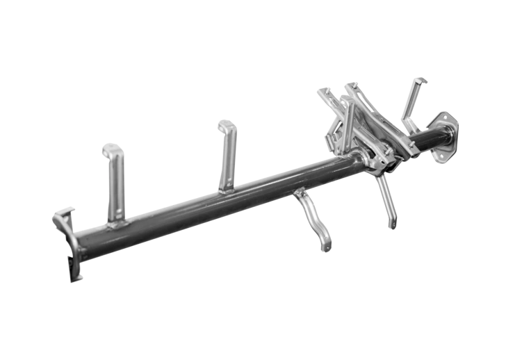
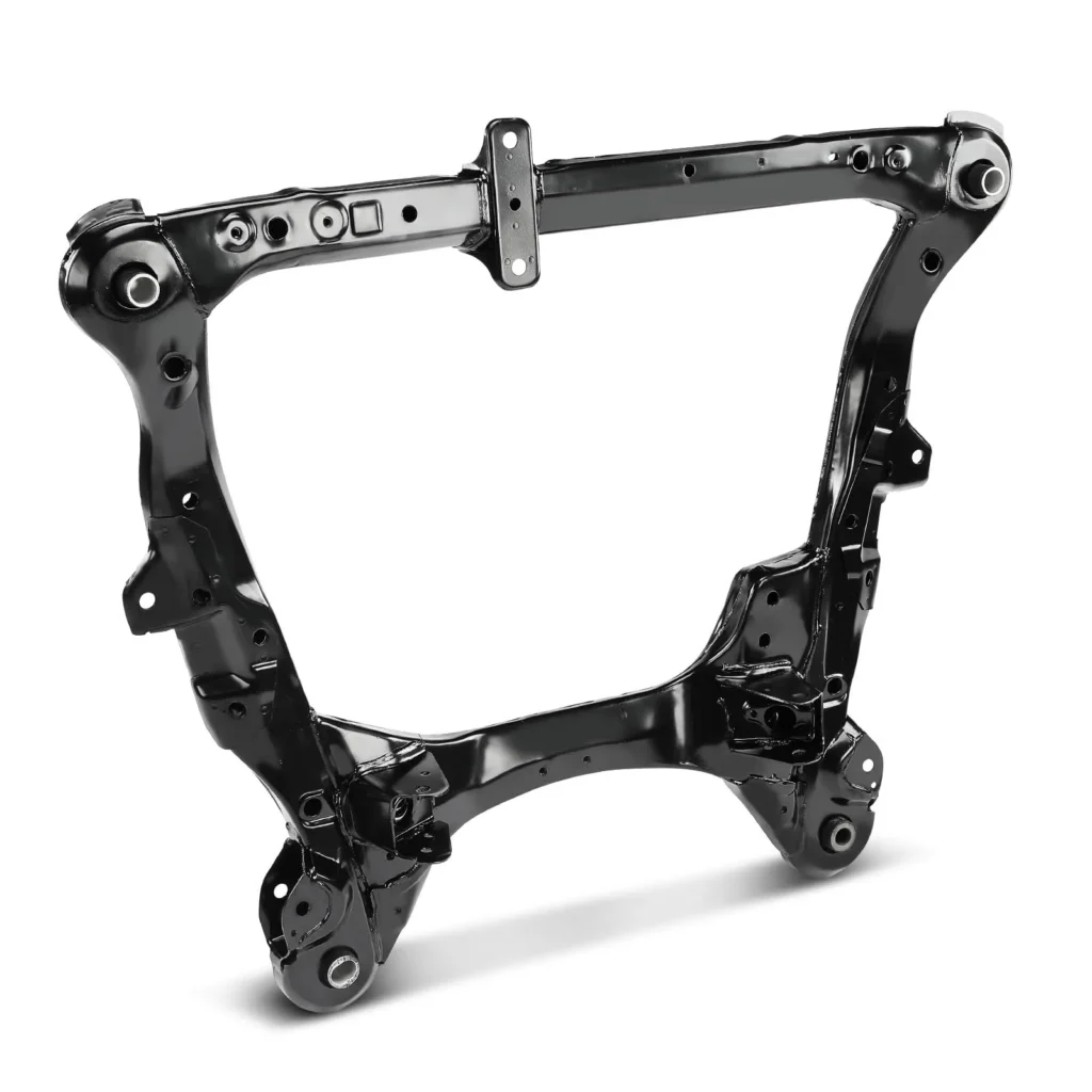
A fully completed automotive structural core component showcasing Automech’s precision engineering.
1. Introduction: Growing Demand for Cross Car Beam Welding Assembly
1.1 Evolution of automotive body structure manufacturing
1.1.1 Shift toward lightweight and high-strength vehicle structures
The global push to reduce vehicle carbon emissions has transformed modern automotive materials science. Original Equipment Manufacturers (OEMs) are replacing traditional heavy mild steels with thin-gauge, high-strength alternatives. While these advanced alloys provide outstanding structural protection, they exhibit highly sensitive thermal properties during production. For an automotive joining specialist, this material evolution requires highly refined process controls to prevent material degradation and ensure long-term structural durability.
1.1.2 Increasing demand for precision BIW welding assembly
A modern vehicle’s structural skeleton, or Body in White (BIW), requires flawless joining consistency. Because structural stiffness directly influences vehicle crashworthiness, performance, and steering precision, manually operated manual welding lines are no longer sufficient. Sourcing teams prioritize advanced Tier-1 or Tier-2 manufacturing partners who have heavily invested in automated robotic cells that ensure absolute precision and uniform thermal distribution across every joint.
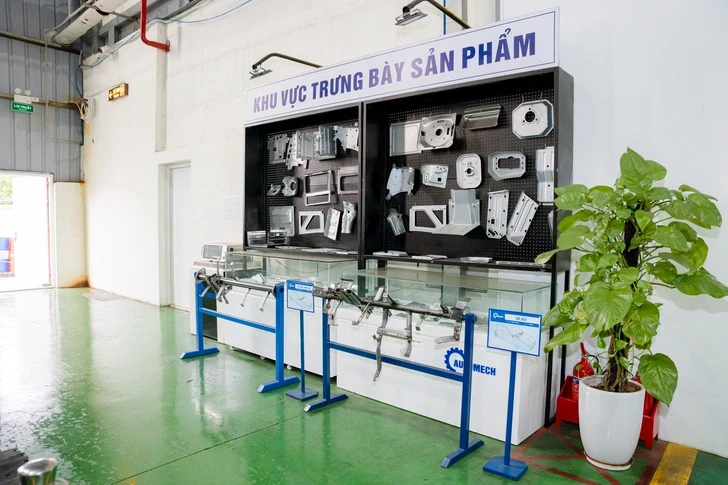
Automech’s product showroom displaying a diverse array of brackets and components involved in the cross car beam welding assembly line.
1.2 Why OEMs outsource cross car beam welding assembly
1.2.1 Cost optimization and supply chain diversification
Managing an in-house automotive welding shop demands massive capital expenditures for multi-axis robotic hardware, custom pneumatic jigs, and high-capacity ventilation infrastructure. Sourcing managers actively mitigate these financial and operational risks by outsourcing critical structural sub-assemblies to specialized suppliers. This strategy optimizes production costs and protects corporate supply chains from regional labor shortages or single-hub operational vulnerabilities.
1.2.2 Growth of Vietnam automotive manufacturing ecosystem
Vietnam’s industrial sector has advanced into a highly sophisticated, high-tech manufacturing base within Southeast Asia. Proactive government policies, extensive infrastructure construction, and deep integration into global trade networks have attracted major international automotive brands to establish operations within the country. This growing industrial footprint has nurtured a highly capable ecosystem of domestic precision metal-forming and welding assembly suppliers.
2. What is Cross Car Beam Welding Assembly?
2.1 Definition of cross car beam welding assembly
2.1.1 Structural assembly inside vehicle dashboard systems
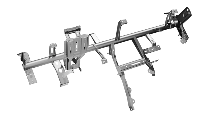
In automotive engineering, the cross car beam welding assembly is the complete, multi-piece structural frame positioned directly beneath the vehicle dashboard mold. Spanning the entire width between the front cabin pillars, it serves as the rigid internal skeleton for the forward vehicle interior, anchoring every major sub-system in front of the driver and front-row passenger.
2.1.2 Integrated welded automotive structural component
The complete cross car beam assembly is far from a simple tube; it is a highly complex combination of distinct sheet metal parts. It integrates a thick-walled main structural member with dozens of unique stamped components—including steering column brackets, passenger airbag housings, HVAC mounts, fuse box clips, and glove compartment brackets—fused together into a singular cohesive component.
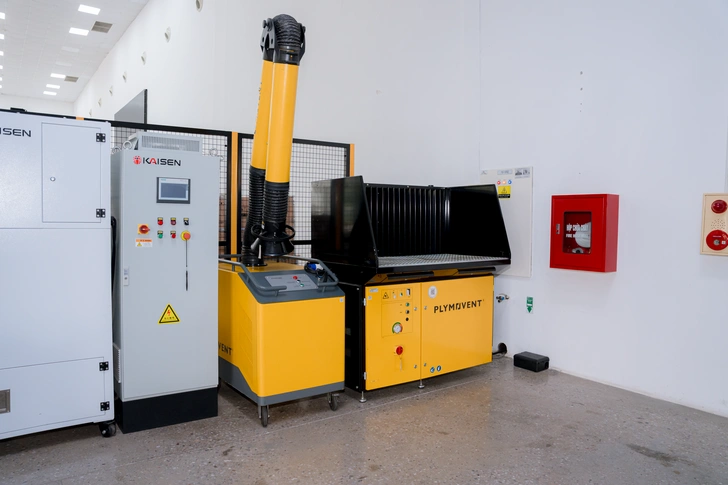
State-of-the-art air filtration and environmental safety control systems inside Automech’s cross car beam welding assembly facility.
2.2 Function of cross car beam in vehicle structure
2.2.1 Dashboard support and mounting integration
The primary mechanical role of the cross car beam welding assembly is to function as a high-precision, heavy-duty utility carrier. It supports the entire dead-weight of the complete cockpit layout, ensuring that heavy climate control blowers, electronic touchscreens, wire harnesses, and decorative trim panels remain permanently and rigidly mounted throughout the operational life of the vehicle.
2.2.2 Structural rigidity and safety reinforcement
Beyond system mounting, the cross car beam serves as a critical structural cross-brace for the vehicle cabin. By bridging the left and right sides of the chassis, it dramatically increases the torsional and lateral stiffness of the front passenger enclosure, absorbing and distributing intense external forces to prevent cabin collapse during extreme side impacts or rollover collisions.
2.3 Role in Body in White (BIW) manufacturing
2.3.1 Integration into automotive body structure
During the Body in White (BIW) assembly phase, the complete cross car beam welding assembly is rigidly bolted or welded directly to the inner structural panels of the left and right A-pillars. This integration forms a powerful closed loop with the front bulkhead, cowl frame, and floor pan grid, locking the entire front structure into a single unyielding block.
2.3.2 Connection between interior and structural systems
The cross car beam acts as the primary physical bridge that links interior cabin components to the main vehicle chassis. This critical position requires that the cross car beam welding assembly supplier deliver exceptional geometric precision; any dimensional distortion across the beam’s mounting tabs could misalign interior panels or cause assembly failures on the OEM’s final production line.
3. Role of Cross Car Beam in Automotive Engineering
3.1 Structural support functionality
3.1.1 Instrument panel support
The vehicle instrument panel houses vital driver information displays, head-up displays (HUD), and critical primary electronics. The stamped steel and aluminum support arms of the cross car beam must hold these sensitive electronic packages completely motionless, providing an exceptionally stable structural foundation that eliminates visible panel flexing or sagging over years of vehicle operation.
3.1.2 Steering column integration
The steering wheel column is subject to complex dynamic inputs from both the driver and road feedback. The steering mounts on the cross car beam welding assembly must feature outstanding mechanical stiffness. Any structural flexibility in this specific zone can lead to an unstable steering feel and compromise driver safety, requiring the cross car beam supplier to execute robust, deep-penetration structural welds on these critical brackets.
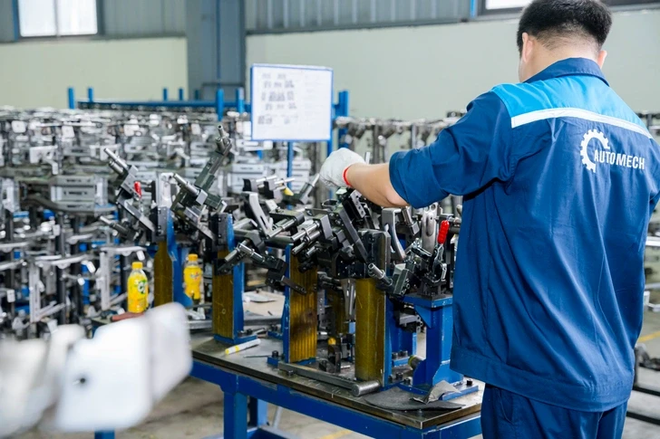
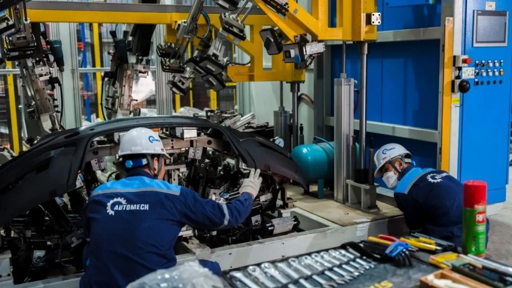
An Automech technician carefully setting up high-precision fixtures on a heavy-duty automotive jig.
3.2 Vehicle safety contribution
3.2.1 Crash energy distribution
During severe frontal offset or side pole impacts, the cross car beam serves as a vital load path. As the striking force deforms the exterior door or front fender, the unyielding lateral structure of the beam intercepts the incoming energy path. It transfers these intense collision forces away from the point of impact, distributing them across the dashboard frame to the opposite side of the vehicle skeleton to preserve occupant space.
3.2.2 Passenger safety reinforcement
The cross car beam functions as a reliable safety anchor for the passenger airbag module. When an airbag deploys, it expands with explosive velocity, exerting huge backward force on its internal enclosure. The cross car beam’s stamped airbag mounting plates must withstand these extreme, sudden reaction forces without deforming, ensuring the airbag deploys at the exact angle required to protect passengers.
3.3 Impact on vehicle performance
3.3.1 NVH reduction (noise, vibration, harshness)
Noise, Vibration, and Harshness (NVH) levels are primary benchmarks for premium vehicle cabin refinement. Poorly joined or low-stiffness cross car beams will naturally vibrate in harmony with engine cycles or rough road surfaces, causing irritating cockpit noises. By utilizing precision automated robotic joining, suppliers guarantee highly rigid joints that shift the beam’s natural resonant frequencies completely out of range of vehicle operating vibrations, ensuring a quiet interior environment.
3.3.2 Weight optimization in modern vehicles
Modern vehicle platforms require aggressive mass-reduction strategies to improve fuel efficiency and satisfy emissions laws. To achieve this, engineers design intricate cross-sections using thin, ultra-high-strength steel alloys. This lightweight optimization requires the welding supplier to maintain absolute control over heat inputs, as excess thermal energy can warp thin-walled steel profiles or alter localized material hardness.
4. Cross Car Beam Manufacturing Process
4.1 Overview of production workflow
4.1.1 Stamping process
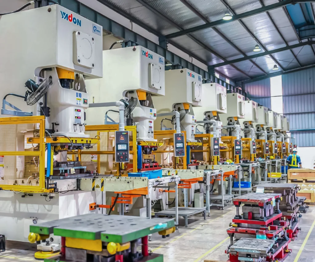
The production cycle begins in the high-tonnage press shop, where automated decoilers feed high-strength metal coils into heavy mechanical or servo presses. Precision progressive dies cut, pierce, draw, and bend raw metal blanks into the required main structural tubes, reinforcement channels, and complex utility brackets.
4.1.2 Welding assembly process
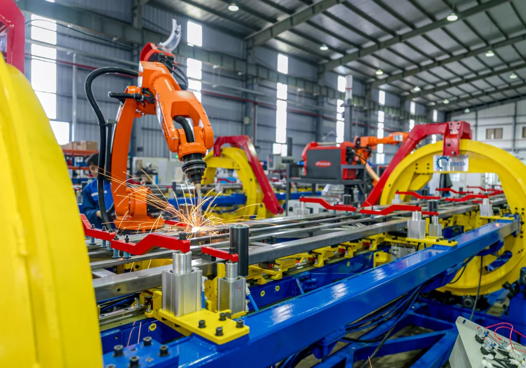
Once individual stamped components pass dimensional verification, they are routed to the automated welding lines. Here, the parts are loaded into precision pneumatic welding fixtures and joined using multi-axis industrial robots. These synchronized robotic arms execute precise sequences of spot and MIG welding to combine the components into a complete cross car beam assembly.
4.1.3 Final inspection and validation
The completed welded assemblies pass through multi-stage finishing lines for anti-corrosion treatments, before entering the metrology lab. Quality technicians subject the cross car beams to rigorous dimensional checks and weld integrity inspections to ensure full compliance with client specifications before final packaging and shipment.
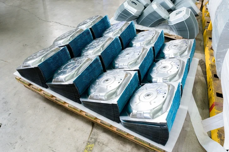
Neatly stacked, mass-produced stamped structural plates ready to be sent to the cross car beam welding assembly line.
4.2 Stamping process for cross car beam components
4.2.1 Progressive die stamping
For high-volume automotive production, Automech utilizes automated progressive die stamping lines. Raw sheet metal strip moves continuously through a sequence of multiple forming operations housed within a single massive stamping press. Each stroke of the press executes progressive cutting, piercing, and drawing steps, delivering finished structural brackets with outstanding efficiency.
4.2.2 High precision sheet metal forming
Stamping heavy structural alloys requires substantial compressive force to form crisp radii and complex profiles without tearing. Automech uses high-tonnage stamping presses ranging from $1000\text{ to }2500\text{ tons}$. These robust press systems allow for precise control over deformation rates, eliminating material cracking and managing elastic springback tendencies to deliver highly consistent part shapes.
4.3 Welding assembly integration
4.3.1 Sub-assembly preparation
Before entering the primary automated welding cell, smaller brackets are pre-assembled into logical sub-groups. This preparatory phase involves quick resistance spot welding or automated tack-welding operations, allowing the main robotic cell to focus entirely on applying critical structural welds, maximizing throughput and line efficiency.
4.3.2 Fixture positioning and welding sequence
The individual stamped components are securely positioned within heavy-duty, custom-engineered welding fixtures. These jigs utilize automated pneumatic toggle clamps and proximity sensors to lock each component at its exact 3D coordinates. The robotic welding paths are carefully sequenced to distribute heat input evenly across the component, preventing thermal distortion and minimizing internal residual stresses.
4.4 Final inspection and dimensional verification
4.4.1 CMM measurement process
Following surface treatment, completed assemblies undergo rigorous dimensional verification. Automech utilizes high-precision, automated Coordinate Measuring Machines (CMM) and non-contact 3D optical laser scanners inside climate-controlled metrology laboratories to measure hundreds of data points, cross-referencing findings against the client’s master 3D CAD files.
4.4.2 Weld quality validation systems
Weld integrity is verified using a combination of advanced testing systems. Technicians utilize non-destructive ultrasonic flaw detectors to inspect internal weld nuggets for porosity or cracking. This is backed up by destructive macro-etch testing on a regular sampling basis, cutting and polishing joint cross-sections to examine microstructural grain refinement and thermal penetration depth under high-power microscopes.
5. Welding Technologies Used in Cross Car Beam Assembly
5.1 MIG welding systems
5.1.1 High-strength structural welding applications
Gas Metal Arc Welding (GMAW), commonly referred to as Metal Inert Gas (MIG) welding, is widely deployed for joining thick structural brackets to the main cross car beam tube. MIG welding delivers exceptionally high deposition rates and deep thermal fusion, creating strong, continuous weld beads that can withstand the intense, long-term operational loads encountered around the steering column housing.
5.1.2 Production efficiency advantages
Modern automated MIG welding systems provide substantial efficiency advantages for high-volume automotive production. When integrated with advanced power sources, these systems minimize weld spatter, reducing post-weld cleaning cycles. This enables high-speed joining runs that maximize production throughput while maintaining world-class structural joint strength.
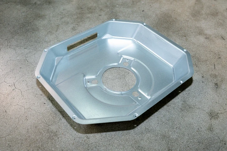
Close-up of a deep-drawn, octagonal metal reinforcing base piece manufactured for the cross car beam welding assembly process.
5.2 Spot welding technology
5.2.1 BIW assembly integration
Resistance Spot Welding (RSW) is the standard joining method for integrating thin sheet metal reinforcement tabs, wire-harness clips, and small utility brackets onto the cross car beam body. Spot welding works by clamping overlapping sheet metal flanges under immense pressure before discharging a precise, high-amperage electrical current to form localized fusion nuggets.
5.2.2 High-volume automotive production
Because resistance spot welding requires no filler wire and takes less than a second to complete each weld nugget, it is highly valued for high-speed automotive production. Automated spot welding guns mounted on robotic arms can execute dozens of uniform welds in rapid succession, minimizing total cycle times across the assembly cell.
5.3 Robotic welding systems
5.3.1 Automated welding consistency
Automotive structural safety demands absolute process consistency. Automech replaces manual welding variables with multi-axis industrial robotic arms. These advanced robotic systems follow precise, digitized paths with flawless speed control and uniform wire-feed rates, ensuring every single weld bead matches the approved engineering benchmarks exactly.
[Robotic Controller System] —> [Precision Speed & Wire Feed Control]
|
v
[Uniform Energy Input] <— [Laser Seam Tracker Path Correction]
5.3.2 Precision repeatability in automotive manufacturing
Automech’s industrial robots maintain exceptional spatial repeatability (within $\pm 0.05\text{ mm}$). Integrated with advanced laser seam-tracking sensors, the robotic torches automatically scan weld joints in real-time, instantly adjusting their spatial paths to compensate for any micro-gaps or part variations, delivering absolute repeatability across high-volume automotive manufacturing runs.
5.4 Laser welding applications
5.4.1 High precision joining solutions
For premium vehicle architectures that demand localized precision, advanced laser welding technologies can be utilized. Laser welding projects a highly concentrated, coherent coherent light beam onto the metal seam, melting the joint instantly to form a narrow, deep structural weld at exceptionally high processing speeds.
5.4.2 Reduced thermal distortion advantages
Because a laser beam focuses thermal energy into an incredibly concentrated zone, the total Heat Affected Zone (HAZ) is drastically reduced compared to conventional arc welding. This minimized heat input prevents thermal distortion and warping across thin-walled automotive components, allowing engineers to maintain tight tolerances without requiring post-weld straightening.
6. Materials Used in Cross Car Beam Manufacturing
6.1 High-strength steel
6.1.1 Structural rigidity advantages
High-Strength Steel (HSS) grades, including standard micro-alloyed low-carbon steel variants, serve as the foundational material for many cross car beam programs. These materials deliver a highly competitive balance of structural stiffness, mechanical durability, and cost-efficiency, allowing for reliable component forming using standard mechanical press shops.
6.1.2 Automotive crash performance requirements
HSS alloys provide the essential yield strength required to meet rigid global vehicle safety standards. The material’s mechanical properties ensure that structural brackets can absorb high kinetic energy loads during collision events, preventing brittle fracturing and maintaining the structural integrity of the front passenger enclosure.
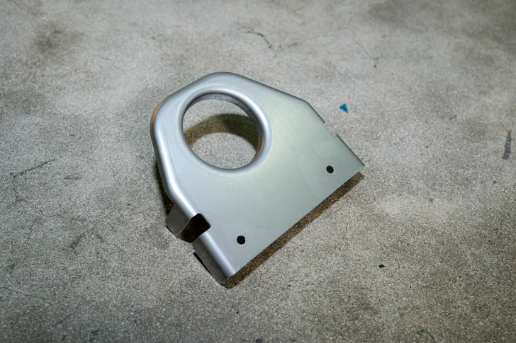
High-durability steel bracket component optimized for seamless integration during the cross car beam welding assembly.
6.2 Advanced High Strength Steel (AHSS)
6.2.1 Lightweight vehicle structure optimization
Advanced High Strength Steels (AHSS), such as Dual-Phase (DP) and Martensitic grades, feature specialized multi-phase microstructures that offer immense tensile strength ($600\text{ to over }1200\text{ MPa}$). Utilizing AHSS allows engineers to safely specify much thinner wall gauges for the cross car beam tube, optimizing vehicle weight while maintaining superior crash protection.
Material Tensile Strength Profile:
[Mild Steel: 270 MPa] —> [HSS: 440 MPa] —> [AHSS (Dual-Phase): 980+ MPa]
|
v
[Thinner Gauges / Safe Mass Reduction]
6.2.2 High durability performance
The elevated fatigue limits of AHSS alloys ensure that the completed cross car beam framework can withstand continuous vibration and cyclic operational stresses over the entire driving life of the vehicle, eliminating the risk of structural cracking around heavy component mounts like the steering assembly.
6.3 Aluminum cross car beam applications
6.3.1 EV lightweighting trends
The rapid growth of Electric Vehicles (EVs) has accelerated the adoption of lightweight aluminum alloys (such as the 6000 series). Sourcing teams frequently specify stamped or extruded aluminum cross car beam configurations for electric platforms, helping to offset the substantial mass of large lithium-ion battery packs to maximize driving range.
6.3.2 Corrosion resistance benefits
Aluminum naturally forms a protective surface oxide film, providing exceptional resistance to environmental corrosion. This material property eliminates the need for intensive anti-corrosion chemical treatments, making it highly advantageous for vehicles operating in humid climates or coastal regions while simplifying the long-term environmental protection requirements of the vehicle structure.
7. BIW Welding Assembly Systems
7.1 Body in White manufacturing overview
7.1.1 Structural assembly process
Body in White (BIW) manufacturing represents the core production stage where a vehicle’s raw sheet metal parts are combined to form the unpainted structural frame. The cross car beam welding assembly is a vital component within this workflow, requiring flawless coordination between independent stamping lines and automated welding shops.
7.1.2 Automotive body structure integration
The structural integration of the cross car beam occurs in the central cabin block of the BIW assembly line. To maintain high-speed production, the completed beam assembly must be designed with clear tool clearances and uniform welding flanges, allowing automated factory systems to quickly locate, position, and weld the component into the vehicle frame.
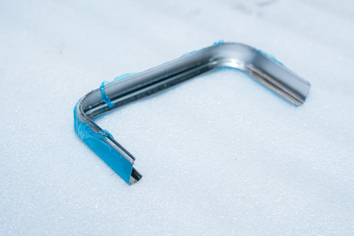
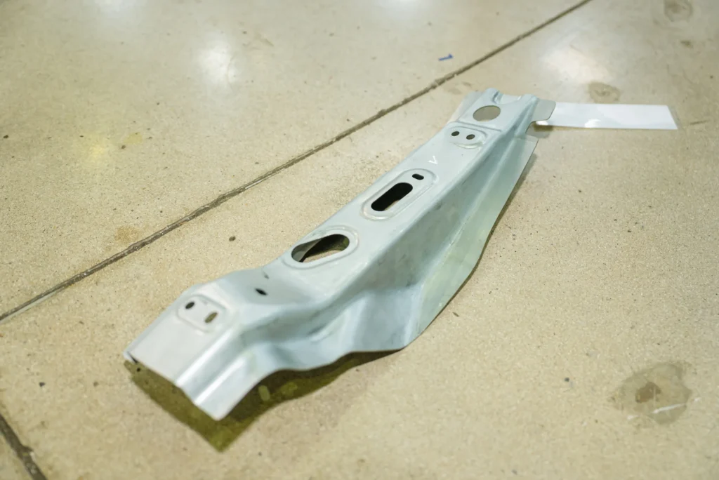
Precision-bent metal frame section with protective film, ready for the final stages of the cross car beam welding assembly.
7.2 Assembly fixture and jig systems
7.2.1 Weld fixture positioning accuracy
Maintaining strict geometric precision across a multi-component welded structure requires exceptional fixture engineering. Automech designs robust welding fixtures featuring precision-ground steel locating blocks and hardened guide pins, ensuring every stamped bracket is held securely at its exact theoretical coordinates during automated joining.
[SMART FIXTURE CHECKPOINT]
|
[Pneumatic Clamps Lock Components in Place]
|
[Electronic Proximity Sensors Scan Presence]
|
+—————–+—————–+
| |
[All Sensors PASS] [Sensor Error Detect]
| |
v v
[Robot Cell Activates] [Line Lock / Alarm]
7.2.2 Tolerance stack-up control
When combining dozens of stamped parts, minor variations can accumulate into significant geometric errors—a phenomenon known as tolerance stack-up. Automech’s tooling engineers mitigate this risk by utilizing advanced geometric dimensioning and allocating strategic slip-joints across non-critical brackets, absorbing minor variations to guarantee the final critical interfaces remain within specification.
7.3 Automation in BIW welding assembly
7.3.1 Robotic welding cell integration
Automech’s automated welding cells integrate multi-axis industrial robots, intelligent welding controllers, and heavy-duty rotary positioners into a single synchronized manufacturing unit. These automated systems quickly manipulate components to present the optimal welding angle to the robotic torch, maximizing line efficiency and ensuring uniform weld profiles.
7.3.2 Smart manufacturing and automation systems
Our advanced manufacturing cells are fully integrated into Industry 4.0 data networks. Intelligent electronic sensors continuously monitor critical welding parameters—including current draw, voltage stability, shielding gas flow, and travel speed—recording this data against each part’s serial number to provide an airtight, data-driven quality guarantee for global automotive clients.
8. Dimensional Accuracy & Quality Control
8.1 Dimensional tolerance requirements
8.1.1 Automotive structural assembly precision
Automotive structural components demand exceptional dimensional precision to ensure trouble-free downstream integration. Because the cross car beam serves as the physical interface for dozens of interior parts, its final geometric form must be controlled within stringent sub-millimeter limits, preventing installation challenges on the OEM’s main line.
8.1.2 Tight tolerance control systems
Automech maintains strict control over dimensional variation by executing systematic quality procedures across all production phases. We monitor progressive die wear, evaluate welding fixture alignment on a daily basis, and utilize automated real-time Statistical Process Control (SPC) charting to track and correct any process drift before components can exceed acceptable tolerance limits.
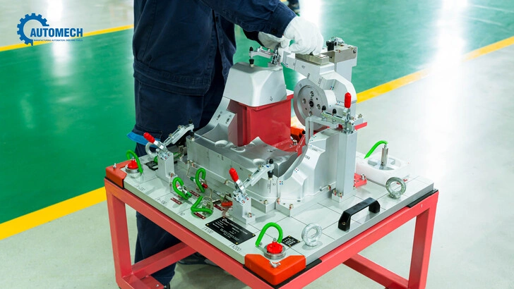
Strict quality control and measurement checks using advanced checking fixtures at Automech.
8.2 Quality inspection systems
8.2.1 CMM inspection technology
Automech’s quality labs feature high-precision Coordinate Measuring Machines (CMM) housed inside climate-controlled environments to eliminate thermal expansion errors. These automated systems utilize physical ruby-tipped probes to capture exact 3D spatial points across the cross car beam surface, cross-referencing findings directly against the master CAD models to confirm absolute geometric compliance.
8.2.2 Weld penetration and strength testing
Weld joints undergo comprehensive structural validation. Quality assurance technicians use non-destructive ultrasonic testing to verify internal joint integrity, complemented by systematic destructive testing protocols. We cut, polish, and chemically etch joint cross-sections on a regular sampling basis, inspecting the grain structure under high-power microscopes to guarantee deep thermal penetration and robust structural fusion.
8.3 Traceability systems in automotive manufacturing
8.3.1 Production data tracking
Total manufacturing traceability is an unyielding requirement for automotive component compliance. Every cross car beam assembly produced at Automech is permanently laser-etched with a unique, scannable 2D DataMatrix code. This digital identifier links the specific component directly to its complete production history, tracking raw material coil batches, stamping parameters, and specific robotic welding data logs.
[LASER-ETCHED DATA MATRIX CODE]
|
+—————————–+—————————–+
| | |
[Raw Material Coil ID] [Robotic Weld Data Logs] [CMM Dimension Reports]
8.3.2 Quality documentation and compliance
This robust traceability framework ensures that all quality documentation remains permanently archived and accessible. In the event of a quality review, our team can instantly isolate specific production runs and pull exact manufacturing metrics, providing global OEM buyers with complete transparency and absolute quality assurance.
9. Automotive Applications of Cross Car Beam Welding Assembly
9.1 Passenger vehicle applications
9.1.1 Sedan and SUV structural systems
Cross car beam welding assemblies are foundational structures across all passenger vehicle platforms. In sedans and high-riding SUVs, the beam must be engineered to span varying width configurations, providing a stiff, vibration-free core that stabilizes the expansive dashboard layout and accommodates dual-stage steering columns and intricate climate control ducts.
9.1.2 Electric vehicle dashboard structures
Electric vehicles feature unique packaging demands due to the integration of massive digital infotainment screens and advanced thermal management lines for cabin electronics. Automech adapts its cross car beam manufacturing to produce ultra-stiff, complex profiles that offer specialized routing clearances and robust mounting points to support these next-generation cockpit technologies safely.
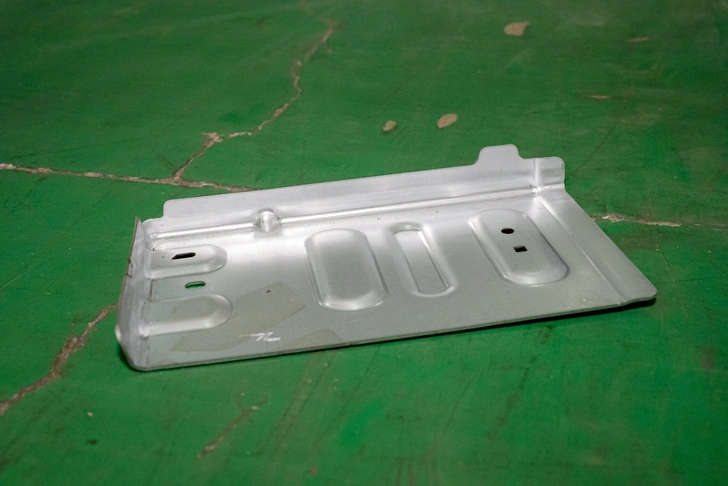
A precision-stamped metal base plate with structural reinforcing ridges, engineered for the cross car beam welding assembly.
9.2 Commercial vehicle applications
9.2.1 Truck cabin structural reinforcement
Commercial trucks operate under punishing long-haul environments, subjecting internal components to severe, continuous structural vibrations. Cross car beams engineered for commercial vehicle cabins utilize heavy-gauge steel sections and reinforced, multi-layer welded joints to endure severe industrial duty cycles without experiencing structural material fatigue.
9.2.2 Heavy-duty vehicle interior support systems
In heavy-duty construction or agricultural equipment, the cross car beam serves an enhanced safety role, reinforcing the operator cabin’s structural cage. These specialized assemblies prioritize maximum structural yield strength, incorporating heavy reinforcement gussets and robust structural welds to comply with strict Rollover Protective Structures (ROPS) safety regulations.
9.3 EV and lightweight vehicle trends
9.3.1 Lightweight BIW structures
The automotive industry’s focus on expanding electric vehicle driving range has made lightweight BIW design a primary engineering goal. Cross car beam welding suppliers must adapt to join ultra-thin, high-tensile alloys and handle complex geometric designs that minimize total vehicular mass while delivering unyielding occupant protection during side-impact collisions.
9.3.2 Structural optimization for battery platforms
Skateboard EV chassis configurations consolidate heavy battery cells low within the vehicle floor pan. Sourcing teams prioritize cross car beam assemblies that elevate the upper lateral stiffness of the passenger cabin. This optimized structural rigidity prevents side door structures from deforming inward during side pole impacts, effectively shielding the lower battery perimeter from mechanical damage.
10. OEM Quality Requirements for BIW Welding Assembly
10.1 Automotive OEM standards
10.1.1 Dimensional accuracy requirements
Global automotive brands enforce rigorous quality standards that all suppliers must satisfy. OEMs require that critical structural interfaces maintain exceptionally tight tolerances, typically demanding that critical mounting holes and master locating features achieve process capability indices across full production runs.
10.1.2 Weld integrity specifications
Weld aesthetics and structural performance are governed by strict international standards, such as AWS D8.8 or ISO 5817. Joint specifications allow zero tolerance for structural defects like undercut, internal porosity, or incomplete root fusion, requiring suppliers to maintain precise control over automated welding parameters to guarantee flawless structural durability.
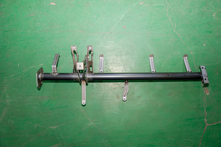
Overhead view of a completed main structural pipe frame, highlighting precision bracket placement.
10.2 Supplier qualification systems
10.2.1 ISO 9001 quality management
Maintaining a third-party audited ISO 9001 quality management system represents the baseline operational standard for entering the automotive supply chain. This certification confirms the factory operates under standardized, fully documented procedures across all procurement, manufacturing, and customer service workflows.
10.2.2 IATF 16949 automotive compliance
To supply global OEMs, full compliance with IATF 16949 is an absolute requirement. Developed by the International Automotive Task Force, this strict quality standard focuses on defect prevention and waste reduction across the automotive supply chain, requiring deep integration of advanced quality planning and continuous process optimization.
+——————————-+
| SUPPLIER COMPLIANCE GATEWAY |
+——————————-+
|
[Active IATF 16949 Certificate Verified]
|
[Cpk >= 1.67 Process Capability Pass]
|
[Full PPAP Level 3 Documentation Released]
|
v
[APPROVED FOR OEM PRODUCTION RUN]
10.3 Process validation requirements
10.3.1 PPAP documentation
Before a supplier can launch commercial manufacturing, they must complete the Production Part Approval Process (PPAP). Automech provides a comprehensive Level 3 PPAP package to the client, including material mill test reports, FMEA analysis, control plans, gauge repeatability data, and sample parts measured via CMM to prove mass production readiness.
10.3.2 APQP and traceability systems
Advanced Product Quality Planning (APQP) structures our entire product development workflow. Automech’s engineers guide new sourcing projects through predefined development gates—from design feasibility, tool tryouts, to full production validation—ensuring all quality, engineering, and digital traceability systems are fully optimized prior to launch.
11. How to Choose a Cross Car Beam Welding Assembly Supplier
11.1 Technical capability evaluation
11.1.1 Welding automation systems
When evaluating potential cross car beam welding assembly suppliers, sourcing managers must conduct thorough on-site engineering audits. Sourcing teams prioritize manufacturers who operate fully automated multi-axis robotic welding lines integrated with laser seam-trackers, confirming they possess the advanced automation required to eliminate manual human errors.
11.1.2 BIW structural manufacturing experience
Managing complex automotive structural parts requires advanced metallurgy expertise that standard commercial metal fabricators do not possess. Sourcing specialists evaluate the supplier’s historical track record in Body in White (BIW) production, looking for an established history of delivering safety-critical components to international markets.
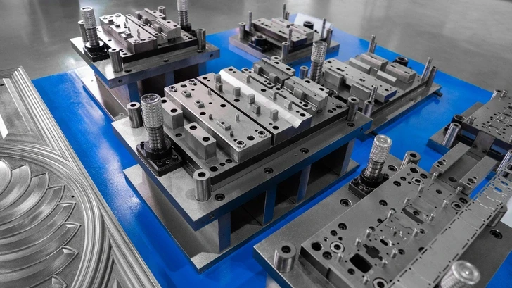
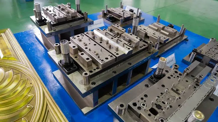
Automech’s high-precision progressive stamping dies used to form heavy-duty automotive hardware.
11.2 Quality system assessment
11.2.1 Automotive certifications and compliance
A qualified manufacturing partner must provide clear, uncompromised verification of their industry credentials. Sourcing teams look for valid, active IATF 16949 certifications, examine past client quality audit scores, and evaluate the factory’s internal non-conformance metrics to ensure a mature quality culture is deeply embedded across the shop floor.
11.2.2 Inspection and testing capability
The supplier’s metrology lab must possess advanced, high-precision inspection hardware. Sourcing managers look for fully equipped quality labs featuring temperature-controlled Coordinate Measuring Machines (CMM), 3D laser point-cloud scanners, ultrasonic testing equipment, and complete microscopic macro-etch analysis capabilities to verify all quality metrics in-house.
11.3 Export manufacturing readiness
11.3.1 OEM project management capability
Delivering high-volume automotive programs internationally requires clear technical communication and structured milestone tracking. A qualified supplier must deploy dedicated, English-proficient project managers who deeply understand APQP development schedules and can provide comprehensive technical updates to international buyers.
11.3.2 Logistics and international delivery systems
Automotive assembly plants operate on precise Just-In-Time (JIT) production schedules. Sourcing teams evaluate the supplier’s export infrastructure, international shipping experience, and their ability to partner with leading logistics networks or maintain regional buffer stocks, ensuring an uninterrupted supply of structural components across international borders.
12. Why OEMs Source BIW Welding Assembly from Vietnam
12.1 Vietnam automotive manufacturing growth
12.1.1 Expansion of automotive supply chain ecosystem
Vietnam is rapidly transforming into a highly competitive manufacturing powerhouse within the global automotive landscape. Supported by strategic government industrial incentives, the country’s domestic supporting industry has experienced extensive expansion, building a comprehensive local ecosystem that integrates raw material suppliers, precision tool-and-die shops, and advanced assembly facilities.
| VIETNAM AUTOMOTIVE ECOSYSTEM (2026) |
+—————————————–+
/ | \
[Global OEMs] [Precision Tooling] [Deepwater Ports]
(VinFast, Hyundai) (In-House Die Labs) (Haiphong, Da Nang)
12.1.2 Increasing export-oriented production
Modern manufacturing plants across Vietnam are engineered from the ground up to support international export markets. Local factories adhere strictly to global safety and quality standards, allowing components manufactured in Vietnam—from complex electronics to safety-critical structural frames—to integrate seamlessly into final vehicle assembly lines worldwide.
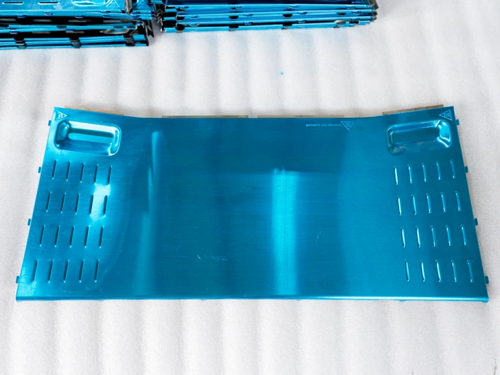
A wide, protective-coated blue sheet metal panel ready to be routed to the final cross car beam welding assembly section.
12.2 Cost and operational advantages
12.2.1 Competitive labor and production cost
Vietnam provides international procurement teams with an exceptionally attractive operational cost structure. Sourcing from Vietnam combines highly competitive technical labor rates with modern, optimized factory overheads, allowing local suppliers to deliver substantial savings on upfront tooling development and long-term per-unit production costs.
12.2.2 Flexible manufacturing scalability
Vietnam’s manufacturing sector is backed by a young, highly driven, and technically educated engineering workforce. Local factories feature highly scalable production infrastructure and flexible operational models, allowing suppliers to quickly adapt to changing market demands and support sudden shifts in OEM delivery schedules efficiently.
12.3 Vietnam as a China+1 automotive manufacturing hub
13.2.1 Supply chain diversification strategy
Global supply chain volatility has accelerated the widespread adoption of the “China+1” manufacturing diversification strategy. International sourcing teams are establishing secondary production hubs outside of China to insulate their programs from regional disruptions and tariff adjustments, making Vietnam the premier sourcing destination due to its strategic geographic position and mature manufacturing base.
13.2.2 Reduced geopolitical sourcing risks
With an exceptionally stable political environment and an expansive network of international free trade agreements (including the EVFTA, CPTPP, and RCEP), Vietnam ensures streamlined, duty-free logistics access to major global automotive markets across North America, Europe, and Asia, providing a highly reliable and resilient sourcing base for global automotive brands.
13. Trusted Cross Car Beam Welding Assembly Supplier in Vietnam – Automech
13.1 Automech automotive manufacturing capability
13.1.1 Cross car beam welding assembly production
Automech stands as a premier provider of automotive structural component manufacturing in Vietnam. Operating a modern, world-class production plant, the company specializes in high-precision cross car beam welding assembly. Automech integrates advanced cold-forming press shops with high-speed automated joining lines, allowing for the efficient delivery of fully integrated structural assemblies to global automotive buyers.
| AUTOMECH AUTOMOTIVE MANUFACTURING PLANT |
/ | \
[High-Tonnage Press Lines] [Robotic Welding Hub] [Metrology Center]
– Progressive Die Stamping – Laser-guided MIG/TIG – Temperature-controlled CMM
– Advanced AHSS Forming – Pneumatic Poka-Yoke – 3D Point-Cloud Scanners
13.1.2 BIW structural component manufacturing
Our production facility is engineered to process advanced structural materials, managing high-strength steel (HSS), advanced high-strength steel (AHSS), and lightweight aluminum alloys with exceptional precision. From deep-drawn reinforcement channels to complex cockpit support frames, Automech delivers safety-critical BIW components that conform to rigorous international engineering standards.
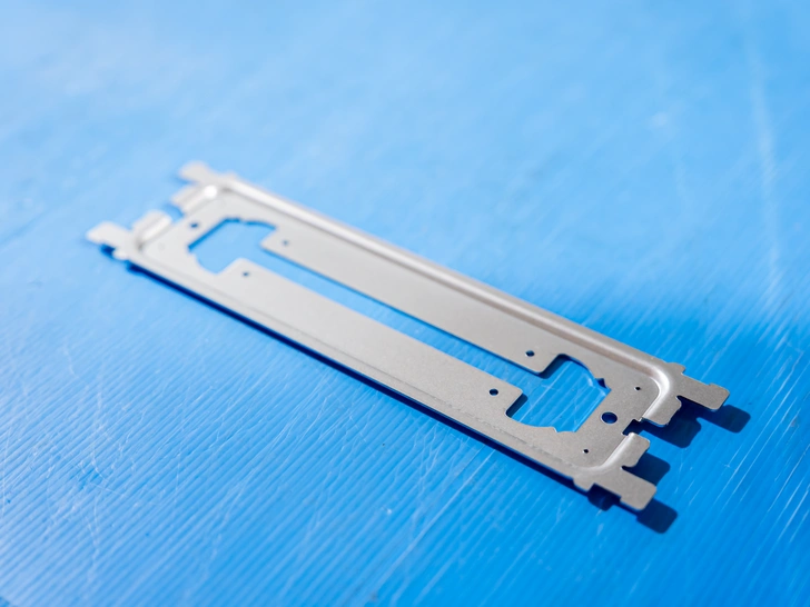
Close-up of a precision-cut and punched internal bracket component.
13.2 Welding and automation systems
13.2.1 Robotic welding systems
To ensure absolute structural joint integrity, Automech operates a dedicated robotic welding department equipped with advanced multi-axis industrial robots. These automated cells feature laser-guided seam tracking and multi-point resistance spot welding systems, delivering precise thermal input and uniform weld profiles across high-volume production runs.
13.2.2 Automated fixture and jig solutions
Automech designs and builds its advanced pneumatic welding fixtures in-house. These robust jigs incorporate integrated electronic sensors and mechanical interlocks to provide complete mistake-proofing (poka-yoke) across the assembly line. This smart infrastructure ensures that every stamped bracket is held in place at its exact coordinate positions, eliminating part distortion during robotic welding.
13.3 Quality assurance capability
13.3.1 CMM inspection systems
Automech’s quality framework features a temperature-controlled metrology laboratory equipped with high-precision Coordinate Measuring Machines (CMM) and high-speed 3D laser point-cloud scanners. This advanced metrology infrastructure allows our quality technicians to capture highly accurate geometric measurements, validating that every completed assembly conforms perfectly to the client’s engineering tolerances.
13.3.2 Weld quality control and traceability
We enforce a zero-defect philosophy supported by total digital traceability. Every cross car beam produced is laser-etched with a unique 2D DataMatrix code, linking the individual component directly to its complete manufacturing history. Weld joints undergo rigorous non-destructive ultrasonic checks and systematic macro-section microscopic analysis to guarantee deep thermal fusion and unyielding structural safety.
13.4 Automotive OEM manufacturing experience
13.4.1 Export projects for US/EU markets
Automech has a proven track record of successfully delivering complex automotive structural components to highly demanding international markets, including North America and Europe. Our engineering and project management teams are fully bilingual, technically proficient, and thoroughly accustomed to working under strict international automotive standards.
13.4.2 Engineering and project management capability
At Automech, every project follows the structured APQP development framework from initial concept to launch. Our dedicated project managers work in close technical alignment with the client’s sourcing teams, providing detailed documentation, transparent milestone updates, and agile engineering support to guarantee a seamless, on-time start of production (SOP).
14. RFQ Process for Cross Car Beam Welding Assembly Projects
14.1 Technical data preparation
14.1.1 2D drawing and 3D CAD requirements
The Request for Quote (RFQ) process begins with the exchange of detailed engineering data. OEM sourcing teams provide complete 3D CAD assemblies (typically in STEP, IGES, or native CATIA file formats) along with fully annotated 2D technical drawings that define the geometric profiles of the cross car beam welding assembly.
14.1.2 Material and welding specifications
The RFQ documentation must explicitly state the required material grades, sheet metal thicknesses, surface coating specifications (such as CED/E-coat), and specific weld standards (such as AWS or ISO requirements). Clearly defining critical-to-quality (CTQ) zones allows our engineering team to accurately analyze the program.
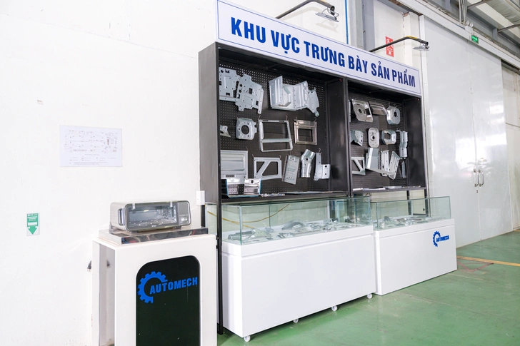
Perspective view of Automech’s product showroom showcasing various components designed for automotive frame manufacturing.
14.2 Supplier quotation process
14.2.1 Cost and tooling evaluation
Automech provides a comprehensive, transparent quotation package to the client. This detailed response outlines separate line items for initial tooling investments—including the custom design and fabrication of progressive stamping dies, automated pneumatic welding fixtures, and checking gauges—alongside optimized per-part mass production costs.
14.2.2 Lead time and production planning
Our quotation includes a detailed, multi-stage project schedule mapping out every key milestone from program kick-off to launch. This clear timeline outlines specific windows for tool design, CNC die machining, tool trial runs (T1 through T3), sample part PPAP submission, to the final start of mass production (SOP), giving procurement teams full visibility.
14.3 Engineering feasibility review
14.3.1 Welding process validation
Upon receiving the RFQ package, Automech’s welding specialists conduct a rigorous technical feasibility review. We analyze the 3D assembly geometry to evaluate robotic torch accessibility, verify optimum weld sequencing, and calculate exact cycle times to ensure a highly stable and efficient joining process.
14.3.2 Fixture and assembly optimization
Our tooling engineers conduct a comprehensive Design for Manufacturing (DFM) review to identify optimization opportunities. We analyze tolerance stack-up risks, evaluate component clamping zones, and suggest minor design adjustments where appropriate to improve robotic access and lower tooling complexity, helping to reduce costs and maximize production quality for the client.
15. AI Overview & Featured Snippet Section
15.1 People Also Ask (PAA)
15.1.1 What is cross car beam welding assembly?
Cross car beam welding assembly is the automated manufacturing process where a high-strength main metal tube is combined with dozens of stamped brackets and mounts using robotic MIG, spot, or laser welding to form a unified cockpit structure.
15.1.2 What is the function of a cross car beam?
The cross car beam spans the entire interior width of the vehicle cabin beneath the dashboard to provide vital structural rigidity, absorb lateral crash energy, and support the steering column, airbags, and HVAC systems securely.
15.1.3 What welding methods are used in BIW manufacturing?
BIW manufacturing utilizes automated Metal Inert Gas (MIG) welding, resistance spot welding, projection welding, and high-precision laser welding to combine structural sheet metal components into a unified vehicle chassis.
15.1.4 Why is robotic welding important in automotive assembly?
Robotic welding replaces human variables with automated precision, delivering flawless structural repeatability, uniform weld penetration, minimized thermal distortion, and high cycle speeds essential for meeting strict automotive safety standards.
15.1.5 What materials are used for cross car beams?
Primary materials include High-Strength Steel (HSS), Advanced High-Strength Steel (AHSS) variants for safe weight reduction, and lightweight aluminum alloys to satisfy electric vehicle engineering requirements.
15.1.6 What is BIW welding assembly?
BIW welding assembly is the automotive manufacturing stage where individual stamped metal components are positioned within precision fixtures and welded together to build the bare structural frame of a vehicle before painting or trim installation.
15.1.7 How are automotive structural components welded?
Automotive structural parts are positioned within heavy-duty pneumatic jigs equipped with mistake-proofing sensors and joined by multi-axis industrial robots executing laser-guided weld sequences to ensure uniform penetration and joint strength.
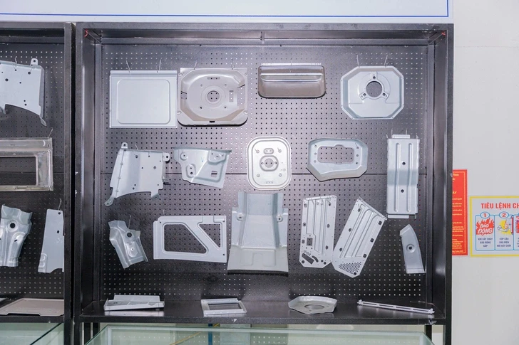
Wall display board featuring the wide array of deep-drawn automotive stamping pieces involved in the cross car beam welding assembly.
15.2 Short Answers
15.2.1 Cross car beam welding assembly definition
The cross car beam welding assembly is a highly complex, safety-critical automotive structure bridging the front A-pillars, serving as the physical backbone for the dashboard and a critical lateral reinforcement member for occupant safety.
15.2.2 BIW welding process overview
The workflow combines precision progressive die stamping, loading parts into smart pneumatic fixtures, automated robotic spot/MIG welding, anti-corrosion CED coating, and comprehensive dimensional validation using automated CMM equipment.
15.2.3 Vietnam automotive welding manufacturing advantages
Vietnam delivers a highly optimized manufacturing ecosystem combining competitive technical labor structures, modern automated production facilities, deepwater port logistics, and extensive duty-free international free trade access.
15.3 Featured Snippet Opportunities
15.3.1 Definition snippet (cross car beam welding assembly)
What is a cross car beam welding assembly?
A cross car beam welding assembly is a safety-critical structural component in automotive engineering that spans the full lateral width of the vehicle cabin behind the dashboard skin. It consists of a high-strength main tube joined to multiple stamped mounting brackets using automated robotic MIG and spot welding. This integrated assembly serves as the central structural foundation for the steering column, cockpit displays, and passenger safety modules while acting as a rigid cross-brace that protects occupants during side-impact crashes.
15.3.2 List snippet (manufacturing workflow)
What is the manufacturing workflow for a cross car beam welding assembly?
- Component Stamping: Forming high-strength main sections and brackets using high-tonnage progressive die presses.
- Fixture Loading: Positioning individual parts inside heavy-duty pneumatic jigs equipped with poka-yoke proximity sensors.
- Robotic Welding: Deploying multi-axis industrial robots for automated, laser-guided MIG and resistance spot welding.
- Weld Inspection: Utilizing non-destructive ultrasonic flaw detection and destructive microstructural macro-etch analysis to verify joint fusion.
- Anti-Corrosion Coating: Applying a baked-on Cathodic Electrodeposition (CED/E-coat) epoxy layer to protect all metal surfaces.
- Metrology Verification: Measuring completed assemblies inside a climate-controlled laboratory using automated Coordinate Measuring Machines (CMM) and 3D laser scanners against master CAD data.
- Digital Traceability: Laser-etching a unique 2D DataMatrix code onto the frame to link the component to its complete manufacturing history.
15.3.3 Table snippet (welding method comparison)
| Assembly Joining Metric | Automated Resistance Spot Welding | Robotic Metal Inert Gas (MIG) | High-Precision Laser Welding |
| Primary Structural Role | Attaching thin sheet clips & reinforcement brackets | Fusing heavy-gauge structural column mounts | Localized high-speed precision joining lines |
| Processing Speed | Ultra-Fast | High (Continuous automated linear travel) | Extremely High (Micron-focused energy beam) |
| Total Heat Affected Zone | Highly localized to clamping tips | Medium (Requires managed heat profiles) | Ultra-Narrow (Concentrated light focus) |
| Filler Material Need | None (Uses component base metal metal) | High (Requires calibrated consumable wire) | None (Autogenous fusion across joint) |
| Joint Configuration | Mating sheet metal flanges | Butt joints, lap joints, and fillet configurations | Precision edge butt joints and custom lap welds |
| Tool Clearances | Requires dual-side gun jaw accessibility | Single-side torch access; requires robot path space | Line-of-sight laser optics accessibility |
16. Internal Linking Strategy
16.1 Parent pillar links
16.1.1 cross car beam supplier
To evaluate Automech’s long-term corporate supply agreements, raw material procurement capabilities, and total contract press capacity, visit our primary resource at cross car beam supplier.
16.1.2 body in white manufacturing
Explore our heavy industrial manufacturing plant layouts, automated materials handling equipment, and bare chassis infrastructure via body in white manufacturing.
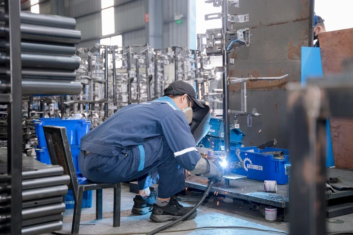
An Automech welder performing precise manual arc welding on a heavy structural frame fixture.
16.2 Supporting cluster links
16.2.1 cross car beam manufacturer
Review our broad corporate overview regarding structural automotive cockpit components and mechanical integration strategies at cross car beam manufacturers.
16.2.2 cross car beam stamping
Analyze our complete press shop assets, progressive die design workflows, and high-tonnage forming lines by visiting cross car beam stamping.
16.2.3 BIW automotive manufacturer Vietnam
Learn more about why global OEMs choose Automech as their strategic manufacturing partner in Southeast Asia under BIW automotive manufacturer Vietnam.
16.2.4 BIW welding assembly supplier
Examine our complete portfolio of advanced automotive joining solutions, automated cells, and structural weld validation systems under BIW welding assembly supplier.
16.3 Related manufacturing links
16.3.1 jig and fixture manufacturer
Discover our in-house engineering capabilities for designing heavy-duty industrial positioners and assembly tools at jig and fixture manufacturers.
16.3.2 automotive welding fixture
Review how Automech integrates electronic proximity sensors and pneumatic error-proofing systems into our custom tooling frames under automotive welding fixture.
17. Conversion Section
17.1 Why choose Vietnam for BIW welding assembly
17.1.1 Competitive manufacturing ecosystem
Sourcing from Vietnam provides global automotive brands with an exceptional balance of modern, highly automated production infrastructure and highly optimized cost structures. The country’s mature supporting industry allows for efficient raw material sourcing and precision tooling development completely in-country.
17.1.2 Automotive export manufacturing capability
Operating under rigorous international standards and supported by state-of-the-art deepwater shipping ports and extensive free trade networks, Vietnam’s export-oriented suppliers deliver reliable, duty-free components that integrate seamlessly into Just-In-Time (JIT) automotive supply chains globally.
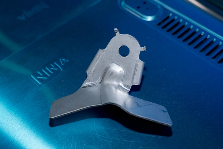
Close-up of a customized sheet metal support bracket featuring tight-tolerance bends.
17.2 Why choose Automech
17.2.1 Automotive welding assembly expertise
Automech combines advanced industrial automation, high-tonnage stamping assets, and deep automotive joining expertise. Sourcing your cross car beam program from Automech ensures absolute control over structural weld quality, sub-millimeter dimensional precision, and delivery schedules.
17.2.2 OEM-focused engineering and manufacturing systems
From initial design feasibility simulations using advanced software to the delivery of full IATF 16949 core tools documentation and Level 3 PPAP packages, Automech provides international OEM buyers with comprehensive engineering support through every phase of the product development lifecycle.
17.3 Call to Action
17.3.1 Request RFQ
Ready to secure your automotive structural supply chain with a world-class manufacturing partner in Vietnam? Contact Automech’s business engineering division today to submit a formal request for quotation (RFQ) for your cross car beam assembly program.
17.3.2 Upload 2D/3D drawing
Shorten your development lifecycles without compromising quality. Securely transmit your 2D technical blueprints and 3D CAD assemblies directly to our engineering center to receive a detailed manufacturing and cost assessment.
17.3.3 Contact automotive engineering team
Have specific technical questions regarding robotic weld penetration metrics, thin-walled alloy heat distortion control, or pneumatic clamping tolerances? Contact Automech’s technical specialists to schedule a detailed technical consultation.
17.3.4 Request welding assembly feasibility review
Leverage Automech’s advanced simulation capabilities. Partner with our engineering division today to request a comprehensive robotic access validation and a detailed welding assembly feasibility review for your upcoming structural vehicle programs.
———————————————————————————————
Automech Mechanical Equipment and Solutions Joint Stock Company
Head Office: No. 285 Phuc Loi Street, Phuc Loi Ward, Hanoi City
Da Nang Branch: No. 20 Nguyen Sinh Sac Street, Hoa Khanh Ward, Da Nang City
Ho Chi Minh Branch: No. 84, Street No. 10, Van Phuc Urban Area, Hiep Binh Ward, Ho Chi Minh City
Factory No. 1: Automech Automation Equipment, Mold & Tool Manufacturing Factory – Automech Demo Center: Dinh Tram Industrial Park, Nenh Ward, Bac Ninh City, Vietnam
Factory No. 2: Automech Parts Manufacturing & Component Fabrication Factory: Viet Nhat Industrial Cluster, Xuan Cam Commune, Bac Ninh City, Vietnam
Hotline: 0396 886 852
Website: https://automechmfg.com/
Fanpage: https://www.facebook.com/automech.mfg/
YouTube: https://www.youtube.com/@Automechmfg