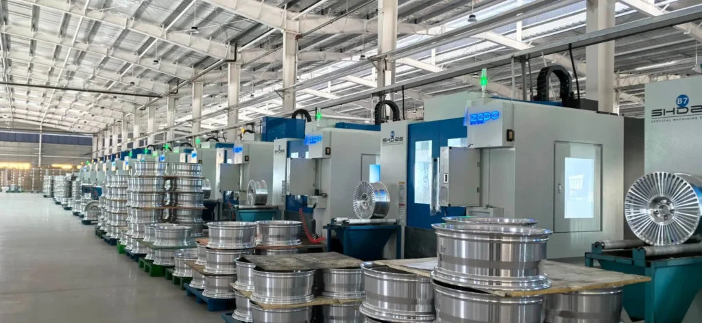
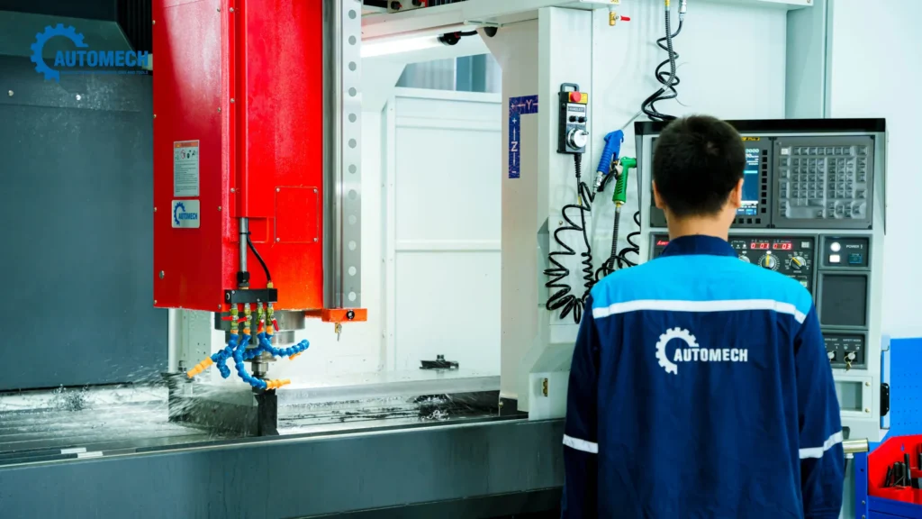
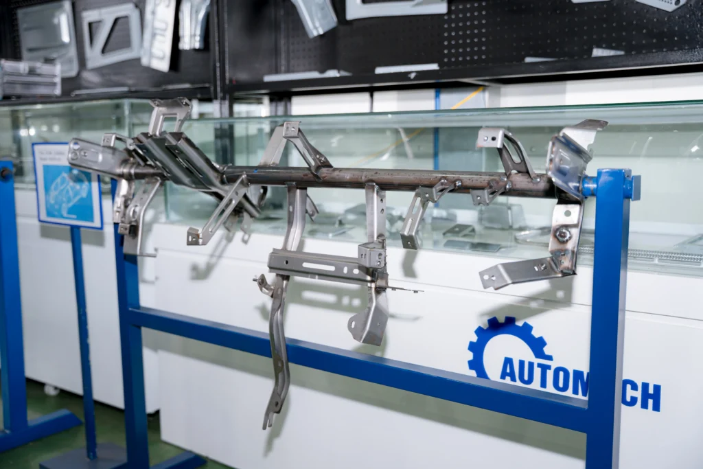
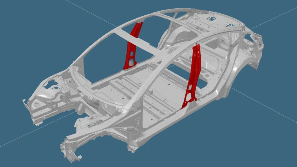
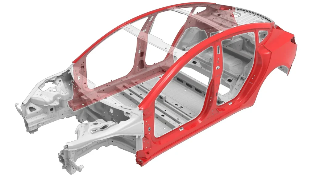
Automotive metal stamping is a foundational manufacturing technology that transforms coiled sheet metal into critical structural, exterior, and functional vehicle components. As global automotive original equipment manufacturers (OEMs) and Tier suppliers accelerate the development of electric vehicles (EVs) and fuel-efficient internal combustion engine (ICE) platforms, high-tonnage mechanical, hydraulic, and servo presses provide the structural scalability needed to meet demanding crashworthiness, lightweighting, and aerodynamic standards. By combining computer-aided die engineering, multi-stage stamping presses, and rigorous automotive quality standards, contract manufacturers convert raw steel and aluminum coils into tightly toleranced vehicle components.
1. Automotive Metal Stamping Overview
1.1 What is automotive metal stamping?
1.1.1 Definition of automotive metal stamping
Automotive metal stamping is a precision cold-forming manufacturing process that utilizes dedicated die sets mounted inside high-tonnage press machines to cut, bend, draw, or coin sheet metal into custom vehicle parts. Guided by computer numerical controls (CNC), the process shapes raw sheet coils or discrete blanks into complex three-dimensional vehicle components without melting the parent material.
1.1.2 Role in producing vehicle components
Automotive stamping serves as the primary production engine for vehicle body-in-white (BIW) structures, chassis assemblies, powertrain housings, and passenger safety cages. The process enables automotive assembly lines to produce millions of uniform metal components annually, delivering the crash-energy absorption and torsional rigidity required for passenger safety.
1.1.3 Difference between automotive stamping and general metal stamping
Unlike general commercial metal stamping which typically adheres to standard industrial tolerances of ± 0.20 mm automotive metal stamping enforces strict geometric dimensioning and tolerancing (GD&T) down to ± 0.01 mm. Automotive stamping also mandates compliance with automotive-specific quality standards (IATF 16949), advanced high-strength steel (AHSS) forming controls, and comprehensive Production Part Approval Process (PPAP) Level 3 documentation.
1.2 Why automotive OEMs use metal stamping

Automotive metal stamping converts flat sheet metal coils into durable structural vehicle components
1.2.1 High-volume production efficiency
Automated stamping press lines operate continuously at speeds ranging from 20 to over 500 strokes per minute, depending on part size and tooling complexity. This throughput enables vehicle manufacturers to meet annual vehicle platform production schedules without creating parts shortages.
1.2.2 Consistent dimensional repeatability
Automotive assembly lines rely heavily on multi-axis robotic welding cells to join stamped components into complete body frames. High-precision stamping dies ensure that feature locations, flange angles, and hole positions match engineering drawings across long production runs, eliminating assembly line fitment issues.
1.2.3 Cost-effective manufacturing for structural and functional parts
Once dedicated tool and die capital is amortized across vehicle program volumes, metal stamping provides one of the lowest unit manufacturing costs in the metalworking industry. High material utilization rates and automated strip feeding minimize raw material scrap and labor overhead per vehicle part.
1.3 Automotive metal stamping in global supply chains
1.3.1 OEM and Tier 1 / Tier 2 supplier requirements
Global automotive manufacturing relies on tiered supply chain networks. OEMs partner with Tier 1 suppliers for complete modular systems (such as seat assemblies, chassis modules, and dashboard structures), while Tier 1 and Tier 2 stamping suppliers manufacture the precision brackets, reinforcement plates, and structural stampings integrated into those modules.
1.3.2 China+1 sourcing and Vietnam manufacturing opportunities
Automotive procurement teams actively implement “China+1” geographic diversification strategies to reduce regional supply chain risks, hedge against tariffs, and enhance manufacturing resilience. Vietnam has emerged as an advantageous manufacturing destination, offering expanding pressworking infrastructure, skilled toolmaking talent, and competitive operational costs.
1.3.3 Demand from US and European automotive buyers
Vehicle manufacturers across North America and Europe actively seek qualified Southeast Asian stamping suppliers to optimize component procurement budgets. Modern Vietnamese stamping suppliers like Automech provide the technical engineering capabilities, IATF-aligned quality systems, and protective export packaging needed to support Western automotive assembly platforms.
2. How Automotive Metal Stamping Works
2.1 Basic working principle
2.1.1 Sheet metal is formed using stamping dies and presses
The metal stamping process positions flat metal sheets or uncoiled strips between matched upper and lower tool steel die blocks mounted in a press bed. When the press ram descends, mechanical, hydraulic, or servo pressure forces the metal into the shape of the die cavity.
2.1.2 Press force shapes, cuts, bends, or draws metal into required geometry
Depending on tool geometry, the stamping press applies localized shear stress to cut openings and perimeter profiles, or controlled compressive and tensile stresses to bend flanges and draw deep cavities. The workpiece yields plastically, permanently holding the intended geometry without structural fracturing.
2.1.3 Tooling accuracy controls repeatability and tolerance
Finished part accuracy depends on die construction. Guide pins, ball-bearing bushings, and CNC-machined die inserts maintain micro-alignment between male punches and female cavities during every stroke, keeping dimensional variance within tight automotive tolerance bands.
2.2 Automotive stamping workflow
2.2.1 Technical drawing and CAD review
The production sequence begins with analyzing customer 2D engineering drawings and 3D CAD geometry. Tool engineers verify geometric dimensioning and tolerancing (GD&T), material stretch limits, hole-to-edge clearances, and bend radii to identify potential manufacturing risks early.
2.2.2 Material selection and blank preparation
Engineers specify automotive-grade raw steel or aluminum coils matching required tensile strengths and formability criteria. Coils pass through motorized uncoilers, multi-roll straighteners to eliminate coil set, and automated servo feeders that deliver flat sheet blanks into the press.
2.2.3 Die design and tooling manufacturing
Toolmakers design multi-station stamping dies using CAD/CAM forming simulation software. Die shoes, punches, and cavity inserts are machined from vacuum-hardened tool steels (such as SKD11, D2, or DC53) using high-precision CNC mills and wire EDM machinery.
2.2.4 Trial stamping and validation
Initial tool tryouts produce physical sample parts for comprehensive inspection. Quality engineers perform 100% First Article Inspection (FAI) and Coordinate Measuring Machine (CMM) dimensional checks, fine-tuning punch clearances and springback compensation geometry before approving mass production.

Precision automotive metal stamping produces tight-tolerance brackets and chassis stiffeners for modern cars
2.2.5 Mass production and inspection
Automated press lines stamp sheet metal continuously at high cycle rates. Statistical Process Control (SPC) protocols, acoustic tonnage monitoring, and in-die optical sensors verify dimensional conformity, ensuring uninterrupted component output.
2.3 Key production factors
2.3.1 Press tonnage
Calculating correct press tonnage ensures the machine delivers sufficient force to overcome the shear and tensile resistance of the material. Heavy automotive brackets and high-strength chassis components require presses ranging from 400 to over 1,300 tons to prevent frame deflection during bottom dead center impact.
2.3.2 Material thickness
Automotive stampings range from thin 0.6 mm exterior skin panels to heavy 6.0 mm structural chassis brackets. Sheet thickness directly governs punch-to-die cutting clearances, stripping force calculations, and required forming tonnage.
2.3.3 Part geometry
Complex geometries such as deep draw pockets, compound flange curves, and embossed stiffening ribs dictate the number of sequential die stations required. Intricate shapes require progressive or multi-stage transfer dies to prevent material wrinkling or tearing.
2.3.4 Tooling durability
Stamping abrasive high-strength automotive steels accelerates die wear. Utilizing premium tool steels and wear-resistant Physical Vapor Deposition (PVD) coatings (such as TiAlN) protects cutting edges, extending die life and maintaining consistent sheared edges over hundreds of thousands of cycles.
2.3.5 Production volume
Vehicle platform lifecycle volumes dictate tooling architecture. Low-volume prototype and service programs utilize single-operation modular dies, whereas multi-year high-volume production programs (exceeding 100,000 units annually) justify fully automated progressive or tandem transfer lines.
3. Automotive Metal Stamping Process
3.1 Engineering and manufacturability review
3.1.1 CAD file and 2D drawing analysis
Engineers import 3D CAD files (STEP, IGES) into specialized metal forming software to evaluate draft angles, draw depths, and bend axes. The review identifies potential forming issues before tool steel procurement begins.
3.1.2 DFM review for stamping feasibility
Design for Manufacturability (DFM) reviews optimize vehicle component designs for pressworking. Tool designers suggest adjustments to bend relief notches, hole spacing, and corner radii to simplify die construction, minimize scrap generation, and prevent part distortion.
3.1.3 Material, tolerance, and surface requirement evaluation
Engineering teams confirm that specified alloy grades provide the required yield strength and percentage elongation for forming. Critical mating surfaces and non-critical external profiles are clearly defined to align tolerance expectations with cost-effective tooling strategies.
3.2 Tool and die preparation
3.2.1 Stamping die design
Tool designers model the entire die assembly in 3D CAD, defining strip progressions, guide pin locations, nitrogen gas spring distributions, and scrap shedding chutes. Balanced station layouts ensure dynamic center-of-force stability under high press speeds.
3.2.2 Die manufacturing and testing
Toolrooms machine die components to tolerances within ± 0.005 mm using high-speed CNC milling and precision wire EDM systems. Following vacuum heat treatment to 58–62 HRC, die shoes are assembled and mounted into tryout presses to test strip progression and part ejection.
3.2.3 Tooling maintenance planning
A preventive maintenance plan is established during tool engineering. Accessible modular inserts, quick-change punch holders, and automated lubrication points allow toolroom technicians to inspect, sharpen, and replace high-wear components with minimal press downtime.

Global vehicle manufacturers utilize automotive metal stamping to meet high-volume production schedules efficiently
3.3 Production process
3.3.1 Blanking and piercing
Blanking cuts the outer contour of the part from the sheet metal strip, while piercing punches mounting holes, slots, and clearance openings. Punches pierce cleanly through the sheet metal, ejecting scrap slugs through lower die relief holes to prevent slug pull-back defects.
3.3.2 Bending and forming
Forming punches apply mechanical bending moments to fold flanges and create curved structural channels along straight or contoured axes. Precision guide pads and calculated over-bend angles compensate for material springback to hold drawing-specified angles.
3.3.3 Drawing and deep drawing
Drawing forces flat sheet metal into hollow female die cavities using a mechanical punch. Controlled blankholder pressure allows the metal to stretch and flow into deep three-dimensional shapes such as motor covers, oil pans, and battery enclosures without wrinkling or tearing.
3.3.4 Progressive or transfer stamping
Depending on component size and volume, parts are processed through progressive dies (retained on a continuous strip carrier) or transfer press systems (using mechanical transfer fingers to move discrete parts between stations) to complete all operations automatically.
3.4 Inspection and validation
3.4.1 First article inspection
Before authorizing mass production runs, quality control teams conduct a full First Article Inspection (FAI) on initial stamped samples. Inspectors verify every drawing dimension, hole location, and material property to confirm complete engineering compliance.
3.4.2 In-process dimensional checks
Operators and automated sensors monitor dimensions at regular production intervals using check fixtures, drop gauges, and micrometers. Tracking key characteristics through Statistical Process Control (SPC) charts detects punch wear early and prevents out-of-spec production.
3.4.3 Final inspection and documentation
Finished production lots undergo final quality verification, including multi-axis Coordinate Measuring Machine (CMM) testing, surface coating thickness checks, and visual burr audits. Inspection data is compiled into formal quality reports and archived for OEM supply chain traceability.
4. Types of Automotive Metal Stamping
4.1 Sheet metal stamping
4.1.1 Automotive panels, covers, brackets, and supports
Sheet metal stamping processes flat steel or aluminum sheets into essential vehicle parts, including protective splash guards, heat shield panels, mounting brackets, and chassis stiffeners. The process delivers balanced structural strength and functional performance for diverse vehicle sub-assemblies.
4.1.2 Flexible production for different part geometries
Sheet metal stamping accommodates a wide variety of automotive part geometries using single-stage, compound, or modular die setups. This flexibility allows manufacturers to produce low-to-medium volume components and manage mid-cycle vehicle design revisions efficiently.
4.2 Precision metal stamping
4.2.1 Tight tolerance automotive components
Precision metal stamping is engineered for safety-critical vehicle components requiring tight dimensional tolerances (down to ± 0.005 mm to ± 0.02 mm). Utilizing high-speed presses and tungsten carbide die inserts, the process manufactures sensor brackets, EV busbar connectors, seatbelt latch plates, and fuel system clips.
4.2.2 High-repeatability stamped parts
By combining rigid die shoes, ground guide pillars, and in-die optical sensors, precision stamping maintains micron-level dimensional repeatability across millions of strokes. This consistency eliminates assembly fitment issues in automated robotic production cells.
4.3 Progressive die stamping

Automotive metal stamping operations include blanking, piercing, bending, forming, and deep drawing processes
4.3.1 Multi-station stamping for high-volume automotive parts
Progressive die stamping feeds a continuous coil strip through a series of sequential stations inside a single die block. Each press stroke performs cutting, punching, bending, and forming operations concurrently while the part advances along the strip carrier ribbon.
4.3.2 Lower unit cost at scale
Separating the completed part from the carrier ribbon at the final station allows progressive dies to run at speeds between 100 and 500+ strokes per minute. This high-speed automation lowers labor expenses and achieves the lowest unit manufacturing cost for high-volume automotive programs.
4.4 Transfer stamping
4.4.1 Suitable for larger and more complex parts
Transfer stamping processes pre-cut discrete sheet metal blanks. Mechanical transfer rails or multi-axis robotic arms physically grip and transfer the individual parts across sequential die stations, freeing the component from the geometric constraints of a continuous coil strip.
4.4.2 Multi-step forming between stations
Because discrete workpieces can be rotated and manipulated between stations, transfer stamping is the preferred method for forming large structural automotive parts, including inner door panels, transmission crossmembers, subframe rails, and multi-flanged floor pans.
4.5 Deep drawing
4.5.1 Producing deep or hollow stamped parts
Deep drawing presses flat sheet metal blanks into hollow cylindrical, box-shaped, or irregularly recessed geometries where part depth exceeds the opening width. The process creates seamless, leak-proof metal containers without welded seam joints.
4.5.2 Managing material thinning and cracking risk
Deep drawing subjects metal to severe radial drawing and tangential compressive forces. Managing draw radiuses, utilizing multi-stage reduction steps, and applying high-performance drawing lubricants controls material flow into the die, preventing side-wall necking, wrinkling, or bottom blowouts.
5. Sheet Metal Stamping for Automotive Parts
5.1 Role of sheet metal stamping in automotive manufacturing
5.1.1 Producing lightweight and repeatable metal parts
Sheet metal stamping serves as the core fabrication process for lightweight automotive components, cold-forming advanced high-strength steels and structural aluminum alloys into rigid contours. By precisely controlling wall thickness variations and forming profiles, manufacturers reduce overall vehicle curb weight without compromising crash impact resistance or mechanical rigidity.
5.1.2 Supporting body, chassis, and assembly systems
Stamped sheet metal parts form the fundamental structural backbone across the entire vehicle architecture. From body-in-white (BIW) monocoque shells to heavy-duty chassis subframe crossmembers, stamping produces consistent interfaces that allow automated robotic welding lines to execute repeatable, defect-free assemblies.
5.2 Common automotive sheet metal parts
5.2.1 Brackets and mounting plates
Automotive brackets and mounting plates provide structural anchors for mechanical, electrical, and powertrain sub-assemblies. Stamped with precise locating holes, stiffening ribs, and mounting tabs, these components secure suspension links, steering columns, and high-voltage electrical inverters against severe vehicle operating vibrations.
5.2.2 Reinforcement components
Reinforcement stampings are strategically positioned throughout vehicle safety zones to manage mechanical load paths during collisions. Stamped from advanced high-strength steels, these parts reinforce door intrusion beams, B-pillar structures, bumper crash boxes, and floor pan longitudinal rails to safeguard passenger cabin integrity.
5.2.3 Covers, guards, and support structures
Protective covers, splash shields, and thermal heat guards shield vulnerable electronic modules and mechanical assemblies from gravel impacts, road salt, water, and engine heat. Stamping enables the integration of mounting bosses, edge curl stiffeners, and ventilation louvers directly into single-piece parts.

Structural body-in-white panels and roof headers require high-tonnage automotive metal stamping press lines
5.3 Sheet metal stamping design considerations
5.3.1 Bend radius
Specifying the correct internal bend radius prevents tensile cracking along outer bend lines and localized necking. For automotive sheet steels and aluminum alloys, the minimum bend radius typically ranges from 1 to 3 times material thickness, oriented perpendicular or diagonal to the sheet rolling grain direction.
5.3.2 Hole spacing
Maintaining adequate spacing between adjacent pierced holes preserves structural integrity across the metal web. Design guidelines require the distance between two pierced holes to be at least twice the sheet thickness (2t) to prevent die matrix wall collapse and localized strip distortion during press impact.
5.3.3 Edge distance
Piercing holes too close to sheet edges causes the unsupported perimeter metal to bulge outward. Automotive stamping guidelines maintain a minimum hole-to-edge distance of at least 1.5 to 2 times material thickness, ensuring uniform sheared edges and straight perimeter profiles for assembly mating.
5.3.4 Springback control
Sheet metals naturally exhibit elastic recovery (springback) when the press ram retracts, altering final bend angles and flange locations. Tool designers counteract springback by integrating calculated over-bending cam angles, bottoming relief steps, or localized coining beads into forming cavities to hold drawing angles within ± 0.25°.
6. Precision Metal Stamping for Automotive Applications
6.1 What makes automotive stamping “precision”
6.1.1 Tight tolerance control
Automotive precision stamping maintains dimensional tolerances between ± 0.005 mm and ± 0.02 mm across critical features, far tighter than standard commercial stamping limits. Precision press beds, micro-ground carbide die inserts, and rigid guide ball-cages eliminate lateral deflection during shearing and forming cycles.
6.1.2 Consistent part geometry across batches
Precision stamping ensures that every component maintains identical physical geometry from the first stroke of a production run to the millionth. Automated servo strip feeding, pilot pin engagement, and active in-die sensing prevent cumulative positioning errors across long manufacturing batches.
6.1.3 Controlled burr and surface finish
Precision automotive stampings require clean sheared edges and smooth surface topographies. Maintaining punch-to-die clearances below 5% of material thickness per side produces full-shear edge walls, restricting exit burr heights to under 5% to 10% of sheet thickness and achieving surface roughness profiles below Ra 0.4 µm.
6.2 Precision requirements for automotive buyers
6.2.1 Dimensional repeatability
Global Tier 1 and OEM buyers require components with predictable dimensional repeatability. Consistent true-position tolerances for pierced holes and flat datum faces ensure that mating fasteners, sensors, and structural dowels engage smoothly without manual adjustment or force-fitting.
6.2.2 Assembly fit and functional performance
Precision stamped components such as seatbelt latch plates, fuel injection clips, and electronic control unit (ECU) shield boxes directly impact vehicle safety and operation. High dimensional accuracy guarantees leak-tight gasket seals, proper spring retention, and smooth mechanical articulation.
6.2.3 Reduced defect rate in mass production
Automotive assembly lines operate on Just-In-Time (JIT) schedules with zero-defect targets (measured in parts per million, PPM). Precision metal stamping incorporates in-die error proofing (Poka-Yoke) to prevent defective parts from reaching customer plants, minimizing assembly line stoppages and warranty claims.

Advanced high-strength steel forming requires robust tooling during high-speed automotive metal stamping cycles
6.3 Precision stamping quality controls
6.3.1 CMM inspection
Coordinate Measuring Machines (CMM) located in climate-controlled testing laboratories (~ 20 °C) inspect complex 3D form profiles, true positions, and geometric dimensioning and tolerancing (GD&T) datums. CMM inspection validates physical parts directly against 3D CAD nominal models.
6.3.2 Gauge inspection
Custom attribute checking fixtures, drop indicator gauges, and go/no-go plug gauges provide fast 100% dimensional verification on the shop floor. These hard gauges simulate downstream vehicle assembly interfaces to confirm immediate fitment before packaging.
6.3.3 First article inspection
Before mass production starts, quality engineers perform a comprehensive First Article Inspection (FAI) on initial stamped parts off the tool. FAI reports verify that die shut-height calibration, strip pitch, and punch offsets yield fully conforming components.
6.3.4 In-process quality monitoring
Statistical Process Control (SPC) protocols track critical part dimensions at regular production intervals. In-die tonnage monitors, laser displacement sensors, and automated optical cameras detect edge wear or material feeding deviations before parts drift out of tolerance.
7. Progressive Die Stamping for High-Volume Automotive Production
7.1 What is progressive die stamping?
7.1.1 Continuous stamping through multiple die stations
Progressive die stamping feeds a continuous metal coil through sequential inline tooling stations integrated inside a single die shoe. Each stroke performs cutting, piercing, coining, and forming operations concurrently while the advancing metal strip carries the workpiece from station to station.
7.1.2 Suitable for high-volume, repeatable automotive components
Progressive dies deliver exceptional efficiency for vehicle platform programs requiring 50,000 to millions of parts annually. The finished component is severed from the carrier strip at the final cutoff station, producing completed parts with minimal human labor and fast machine cycle times.
7.2 Progressive die stamping process
7.2.1 Coil feeding
The process begins with uncoiling sheet metal strip from automated payoff reels, passing the material through motorized roll levelers to remove coil curvature, and advancing it into the die bed using high-speed servo feeders with pitch accuracy within ± 0.01 mm.
7.2.2 Sequential cutting, bending, and forming
Hardened pilot pins enter pre-punched pilot holes at each station to align the strip before the press ram closes. Upper punches descend to shear outer profiles, pierce internal slots, coin chamfers, and bend flanges in synchronized sequence across the die block.
7.2.3 Final part separation
At the final die station, a cutoff punch shears the finished part from the carrier ribbon. Completed components drop through evacuation chutes onto automated packaging conveyors, while scrap skeletons pass into automated scrap cutters.
7.3 Benefits for automotive production
7.3.1 Lower unit cost at high volume
Amortizing upfront die engineering and fabrication expenses over large production volumes yields low piece-part costs. Automated coil feeding, multi-stage tooling, and high-speed operation significantly reduce direct labor and press setup overhead.
7.3.2 Higher production speed
Progressive stamping press lines cycle at speeds ranging from 100 to over 500 strokes per minute, depending on part size and material gauge. This throughput enables suppliers to fulfill high-volume OEM release schedules without creating supply chain bottlenecks.

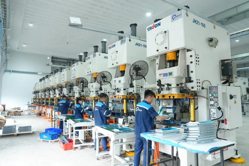
Automotive metal stamping delivers consistent dimensional repeatability across multi-year vehicle manufacturing platforms
7.3.3 Better repeatability and reduced handling
Because the workpiece remains mechanically anchored to the strip carrier throughout all forming stages, transfer alignment errors are eliminated. Automated coil-to-part production avoids manual handling between intermediate machines, reducing part damage and scrap rates.
7.4 Progressive die stamping vs transfer stamping
7.4.1 Process differences
Progressive stamping retains the component on a continuous coiled carrier ribbon through every station within a single die block. Transfer stamping processes pre-cut discrete blanks, moving individual parts across sequential dies using mechanical transfer rails or robotic fingers.
7.4.2 Part size and geometry differences
Progressive die stamping is suited for small-to-medium parts (such as brackets, clips, and terminals) limited by coil strip widths. Transfer stamping accommodates large, deep components (such as body side panels, floor pans, and oil pans) requiring multi-directional manipulation.
7.4.3 Cost and volume considerations
Progressive dies require a single integrated tool block, optimizing high-volume production runs exceeding 50,000 parts per year. Transfer press lines carry higher initial equipment and transfer automation costs, but save raw material expenses on large structural parts by eliminating the scrap carrier ribbon.
| Comparison Metric | Progressive Die Stamping | Transfer Stamping |
| Workpiece Form | Continuous coiled strip carrier | Pre-cut discrete blanks |
| Production Speed | High (100 to 500+ parts/min) | Moderate (15 to 40 parts/min) |
| Component Size | Small to medium structural reinforcements and brackets | Large structural panels and deep shells |
| Material Scrap | Higher (Carrier ribbon scrap skeleton) | Lower (Optimized blank nesting) |
| Target Volume | High volume (> 50,000 parts/year) | Medium to high volume (20,000+ parts/year) |
8. Materials Used in Automotive Metal Stamping
8.1 Carbon steel
8.1.1 Cost-effective structural and bracket components
Commercial cold-rolled low-carbon steels (such as SPCC, SECC, and ASTM A1008) provide an economical balance of tensile strength, ductility, and weldability. They are widely used to stamp engine mounting brackets, cable clamps, and interior seatframe sub-components.
8.1.2 Good strength and formability
Drawing-quality carbon steels (SPCD, SPCE) exhibit high percentage elongation, allowing the sheet metal to undergo multi-axis bends and shallow drawing without localized tearing. These grades are chosen for complex brackets and deep structural covers.
8.2 Stainless steel
8.2.1 Corrosion-resistant stamped components
Austenitic grades (SUS304, SUS316) and ferritic grades (SUS430, SUS409) provide resistance to road salt, chemical exposure, and elevated operating temperatures. They maintain structural strength in severe environments without requiring secondary protective platings.
8.2.2 Applications in harsh operating environments
Stainless steel stampings are standard for vehicle exhaust hanger brackets, catalytic converter heat shields, fuel delivery line clamps, and turbocharger heat baffles exposed to continuous thermal and mechanical stress.
8.3 Aluminum
8.3.1 Lightweight stamped automotive parts
Aluminum alloys (including 5052-H32, 6061-T4/T6, and 5182) feature a density of ~ 2.70 g/cm³, roughly one-third that of steel. Stamping aluminum allows automotive engineers to reduce vehicle curb weight while maintaining structural stiffness and dent resistance.

Modern electric vehicle battery enclosures depend on precision automotive metal stamping for crash protection
8.3.2 EV and mobility applications
In electric vehicles, stamped aluminum components are essential for battery pack enclosures, module tie bars, inverter heat shields, and suspension tower brackets, helping offset heavy battery pack mass to extend driving range per charge.
8.4 High-strength steel
8.4.1 Structural and reinforcement components
High-Strength Low-Alloy (HSLA) steels and Advanced High-Strength Steels (AHSS) including Dual-Phase (DP600, DP800) and Transformation-Induced Plasticity (TRIP) grades provide yield strengths from 350 to 1,000+ MPa. These alloys allow engineers to down-gauge sheet thickness while preserving load-bearing capacity.
8.4.2 Crash-performance-related parts
AHSS components are engineered to absorb and redirect dynamic impact energy during front, side, and rear vehicle collisions. Stamping produces crash-critical parts including bumper beams, B-pillar reinforcement webs, roof header rails, and door intrusion beams.
8.5 Galvanized steel
8.5.1 Corrosion-resistant automotive sheet metal parts
Hot-dip galvanized (GI) and electro-galvanized (EG) steel sheets incorporate a bonded zinc layer that provides galvanic corrosion protection. The zinc barrier protects exposed steel edges from red rust formation throughout the vehicle’s design life.
8.5.2 Exposed or semi-exposed components
Galvanized steel stampings are widely specified for exterior body closures, door inner structures, wheelhouse arch panels, and underbody structural crossmembers exposed to road spray, moisture, and road de-icing chemicals.
9. Automotive Metal Stamping Tooling
9.1 Role of tooling in automotive stamping
9.1.1 Tooling controls part geometry and repeatability
Stamping dies dictate the dimensional accuracy, flange angles, hole locations, and surface contour of finished components. Engineered to micron-level tolerances, tool and die sets replicate CAD geometries across millions of strokes with minimal process drift.
9.1.2 Die quality affects production stability
High-quality tooling reduces unplanned press downtime, eliminates strip feeding jams, and minimizes punch breakage. Precision-guided die sets equipped with nitrogen gas springs maintain consistent clamping forces, ensuring stable production runs on high-speed press lines.
9.2 Types of stamping dies
9.2.1 Progressive dies
Progressive dies integrate multiple sequential piercing, coining, forming, and blanking stations within a single die block. Continuous coil feeding advances the strip through the die, completing a finished automotive component with every press stroke at high speeds.
9.2.2 Transfer dies
Transfer dies consist of separate die stations mounted along a multi-station press bed or across a tandem press line. Mechanical transfer arms move discrete blanks between stations, making them ideal for large, deep structural panels and subframe channels.
9.2.3 Compound dies
Compound dies perform multiple shearing operations such as simultaneous external perimeter blanking and internal hole piercing in a single press stroke at one station. They produce flat, tightly toleranced parts with high hole-to-edge concentricity.
9.2.4 Forming dies
Forming dies apply mechanical bending, flanging, or embossing forces to deform sheet metal without intentionally cutting material fibers. They are engineered to manage material strain, prevent wrinkling, and compensate for elastic springback.
9.3 Tool and die design factors

Tier 1 suppliers combine automotive metal stamping with robotic spot welding for sub-assemblies
9.3.1 Part geometry
Part geometry dictates station counts, draw depths, and punch shapes. Engineers analyze CAD models using finite element forming simulation software to identify deep draw pockets or narrow web sections, ensuring balanced metal flow into die cavities.
9.3.2 Material thickness
Sheet thickness directly dictates punch-to-die cutting clearances (typically 5% to 12% of material thickness per side). Thicker automotive plates require heavier die shoes, larger stripping forces, and robust nitrogen cylinders to manage cutting loads.
9.3.3 Springback behavior
Materials with high yield-to-tensile ratios such as high-strength steels and temper-hardened aluminum exhibit elastic springback after bending. Toolmakers integrate over-bending cam angles and bottoming steps into the die to hold drawing-specified angles.
9.3.4 Expected production volume
Anticipated vehicle program volumes dictate die construction grades. Prototype or low-volume runs utilize modular tool steel inserts in standard die shoes, whereas high-volume OEM programs mandate hardened alloy dies (SKD11, DC53) and carbide cutting punches.
9.4 Tooling maintenance
9.4.1 Preventive maintenance schedules
Structured preventive maintenance schedules follow predetermined press cycle milestones (e.g., every 50,000 or 100,000 strokes). Toolmakers dismantle die blocks to clean guide tracks, inspect nitrogen springs, and lubricate mechanical cam slides to prevent unexpected tool wear.
9.4.2 Wear monitoring and die repair
Operators track punch cutting-edge breakdown and inspect sample parts for burr growth during production. When sheared edges exceed drawing limits, toolmakers perform micro-precision surface grinding on punch faces to restore sharp cutting edges.
9.4.3 Tool life optimization
Applying wear-resistant Physical Vapor Deposition (PVD) coatings such as Titanium Aluminum Nitride (TiAlN) or Diamond-Like Carbon (DLC) reduces surface friction and extends die life. Modular die designs allow rapid replacement of high-wear inserts without rebuilding complete die assemblies.
10. Common Automotive Stamped Parts
10.1 OEM metal stamping parts
10.1.1 Custom stamped parts based on OEM drawings
OEM metal stamping contracts demand custom components fabricated strictly according to customer-supplied 2D drawings, 3D CAD models, and technical specifications. Stamping suppliers maintain tight process controls to satisfy vehicle OEM quality requirements.
10.1.2 Prototype to mass production support
Comprehensive stamping suppliers support vehicle manufacturers throughout product development lifecycles. They provide soft-tool prototype stampings for physical crash testing and vehicle validation before building hardened progressive or transfer dies for high-volume mass production.
10.2 Automotive sheet metal parts
10.2.1 Covers and guards
Stamped covers and protective guards shield sensitive powertrain assemblies, brake lines, and electronic sensors from road debris, mud, and water ingress. Stamping integrates mounting flanges and stiffening ribs to maximize component durability without adding weight.
10.2.2 Reinforcement plates
Reinforcement plates distribute dynamic mechanical loads across vehicle body and chassis joints. Stamped from high-strength structural steel, these parts prevent metal fatigue around suspension attachment points, seat belt anchorages, and door hinge pillars.

High-speed progressive dies optimize automotive metal stamping runs exceeding fifty thousand units annually
10.2.3 Support brackets and frames
Support brackets and subframe cross-members provide rigid mounting points for cooling radiators, air conditioning condensers, steering gears, and dashboard cross-beams. Stamped geometries ensure dimensional alignment for automated vehicle assembly lines.
10.3 Automotive bracket stamping
10.3.1 Mounting brackets
Automotive mounting brackets secure auxiliary motors, exhaust pipes, wiring harnesses, and hydraulic lines within compact packaging envelopes. High-speed progressive stamping produces mounting brackets with integrated clearance holes and alignment tabs.
10.3.2 Structural brackets
Structural brackets carry mechanical and torsional loads between suspension subframes and body-in-white (BIW) nodes. Stamped from heavy-gauge structural steel (2.0 mm to 6.0 mm thick), these components undergo high-tonnage piercing, flanging, and coining to deliver fatigue endurance.
10.3.3 Functional support components
Functional support stampings include pedal mounting brackets, hood latch reinforcements, and seat adjuster brackets. These components require tight dimensional tolerances to ensure reliable mechanical articulation over the operational lifespan of the vehicle.
10.4 BIW and body structure components
10.4.1 Reinforcement parts
Body-in-white (BIW) reinforcement components reinforce critical vehicle structural nodes. Stamped from advanced high-strength steels, these parts reinforce B-pillars, roof side rails, and sill assemblies to manage passenger cabin intrusion during rollover or side-impact collisions.
10.4.2 Cross-member support components
Cross-member support stampings tie longitudinal chassis frame rails together, providing lateral rigidity and resisting torsional vehicle body twisting during high-speed cornering. Precision stamping ensures consistent width dimensions for automated fixture clamping.
10.4.3 Welded stamped assemblies
Individual stamped sheet metal components are joined into modular vehicle sub-assemblies using automated resistance spot welding, robotic MIG welding, or structural adhesives. High-precision stamping ensures that mating flanges fit cleanly into welding jigs without requiring mechanical clamping force.
11. Automotive Stamping Assembly
11.1 Stamping plus welding integration
11.1.1 Spot welding
Resistance spot welding fuses overlapping stamped automotive sheet metal components by applying localized electrical current and mechanical clamping force. It represents the primary assembly method for joining body-in-white (BIW) reinforcements, floor pan crossmembers, and mounting brackets without adding filler wire weight or creating thermal distortion.
11.1.2 MIG/TIG welding
Metal Inert Gas (MIG) and Tungsten Inert Gas (TIG) welding processes provide continuous, high-strength welded seams across heavy-gauge stamped chassis assemblies. Contract manufacturers utilize semi-automated and manual MIG welding to join thick structural suspension brackets, bumper beam assemblies, and motor cradle subframes.
11.1.3 Robotic welding support
Automated robotic welding cells integrate articulated 6-axis industrial robots with multi-station rotary indexing positioners. Multi-axis robotic automation maintains consistent weld bead geometry, penetrates deep structural joints uniformly, and significantly increases production throughput for high-volume OEM automotive programs.

Automotive metal stamping enforces strict IATF 16949 quality management and defect prevention standards
11.2 Fixture-controlled assembly
11.2.1 Assembly fixture design
Precision welding and assembly fixtures utilize CNC-machined locating blocks, hardened dowel pins, and pneumatic toggle clamps to hold stamped sub-components in exact spatial alignment. High-rigidity fixture designs counteract thermal expansion forces generated during high-amperage welding cycles.
11.2.2 Dimensional control during welding
Fixture-controlled workholding eliminates manual operator positioning errors, ensuring that multi-component welded modules maintain uniform dimensional relationships across production batches. Restraining stamped components rigidly during joining prevents angular distortion and holds critical mounting centerlines.
11.2.3 Final assembly validation
Completed welded sub-assemblies undergo dimensional validation using dedicated attribute checking fixtures and Coordinate Measuring Machines (CMM). Quality technicians verify overall spatial envelopes, hole true positions, and weld penetration depth against automotive engineering specifications.
11.3 Benefits of integrated stamping assembly
11.3.1 Reduced supplier complexity
Consolidating sheet metal stamping, mechanical hardware insertion, and secondary welding assembly under a single contract manufacturer simplifies supply chain logistics. Tier 1 buyers benefit from single-source accountability, lower administrative procurement overhead, and shorter production lead times.
11.3.2 Better dimensional consistency
Managing both initial press stamping and downstream fixture welding within the same manufacturing plant enables continuous feedback between production stages. Tooling adjustments in the stamping dies can be implemented immediately to optimize downstream robotic welding fitment.
11.3.3 Improved production accountability
An integrated assembly provider assumes full warranty and quality responsibility for the finished module. In-house quality teams monitor raw coil blanking, forming tolerances, weld seam integrity, and surface treatment, eliminating finger-pointing between separate stamping and assembly vendors.
12. Quality Control Systems for Automotive Metal Stamping
12.1 Incoming material inspection
12.1.1 Material certificate verification
Quality assurance begins by verifying incoming metal coils and sheets against mill test reports (MTR). Quality control inspectors verify chemical composition, tensile strength, yield point, and percentage elongation to confirm raw stock compliance before staging coils at press lines.
12.1.2 Thickness and surface inspection
Inspectors measure raw sheet metal thickness across coil widths using calibrated digital micrometers and ultrasonic gauges to verify gauge tolerances. Visual and optical inspections confirm that coil surfaces are free of rust, scale, roller marks, pitting, and edge lamination defects.
12.2 First article inspection
12.2.1 Initial part approval
Before authorizing mass production press runs, quality inspectors perform a comprehensive First Article Inspection (FAI) on initial stamped parts off the tool. FAI verification confirms that die alignment, press shut height, and feeder pitch produce fully conforming components.
12.2.2 Dimensional and functional verification
Quality engineers inspect all drawing dimensions, bend angles, hole centers, and functional GD&T features using CMMs and optical profile projectors. Mass production commences only after full FAI dimensional approval is formally documented.

Toolmakers design specialized dies to counteract material springback in automotive metal stamping operations
12.3 In-process quality control
12.3.1 Press and die condition monitoring
Modern stamping press lines utilize in-die tonnage monitors, acoustic sensors, and proximity switches to track dynamic stamping forces. Detecting abnormal tonnage spikes halts the press automatically, preventing tool damage from double-blank feeds or misaligned strips.
12.3.2 Dimensional checks during production
Statistical Process Control (SPC) protocols govern active production runs. Press operators sample parts at scheduled intervals to verify critical dimensions using dedicated check fixtures, height gauges, and go/no-go plug gauges, logging data into control charts Cpk ≥ 1.67.
12.3.3 Burr, crack, and surface defect monitoring
Inspectors examine stamped edges and drawn radii for micro-fractures, localized necking, scratching, and exit burr heights. Monitoring edge wear ensures that die maintenance and punch sharpening are scheduled before parts exceed allowable drawing limits.
12.4 Final inspection
12.4.1 CMM inspection
Coordinate Measuring Machines (CMM) located in climate-controlled quality laboratories (~ 20 °C) inspect finished production lots. High-precision tactile probes measure multi-axis true positions, surface profiles, and hole-to-hole center distances against 3D CAD nominals.
12.4.2 Gauge inspection
Custom attribute checking fixtures and receiver gauges provide fast 100% functional verification for high-volume automotive parts. These gauges simulate real-world vehicle mating points to ensure immediate, zero-defect installation on customer assembly lines.
12.4.3 Visual inspection and packaging verification
Final visual checks verify proper surface finishing, plating thickness, complete deburring, and clean packaging. Stamped components are cleaned, count-verified, and packed into corrosion-inhibiting (VCI) bags or customer-specified returnable containers.
12.5 Traceability and quality documentation
12.5.1 Batch traceability
Every production batch receives a unique lot tracking number. Critical automotive parts feature laser-etched 2D DataMatrix barcodes or stamped lot codes linking each finished component directly to its raw material master coil, press machine ID, operator shift, and die maintenance records.
12.5.2 Inspection records
Final shipment packages include complete quality assurance documentation such as CMM dimensional reports, raw material test certificates (MTR), coating thickness logs, and Certificate of Conformance (CoC) records.
12.5.3 Production history for OEM review
Digital quality management systems archive inspection logs, SPC trend charts, and material certifications for 10 to 15 years, providing full audit readiness and long-term warranty traceability for international OEM buyers.
13. ISO 9001 and IATF 16949 Requirements
13.1 ISO 9001 for automotive stamping suppliers
13.1.1 Quality management system foundation
An ISO 9001 certification establishes the baseline Quality Management System (QMS) across all sheet metal stamping operations. It mandates documented standard operating procedures, regular equipment calibration, structured employee training, and management review frameworks.
13.1.2 Process standardization
Under ISO 9001, process standardization ensures that die setup, raw material loading, press operation, and quality inspection follow identical, audited procedures during every production run, minimizing operator-induced manufacturing variations.

Automotive metal stamping processes ductile carbon steel, stainless steel, and lightweight aluminum alloys
13.1.3 Continuous improvement
ISO 9001 drives structured continuous improvement initiatives (Plan-Do-Check-Act cycle). Stamping facilities systematically track machine uptime, scrap generation rates, and tool wear trends to implement corrective actions that optimize production efficiency.
13.2 IATF 16949 for automotive metal stamping
13.2.1 Automotive-specific quality requirements
IATF 16949 extends basic QMS requirements by introducing rigorous automotive-specific standards focused on defect prevention, supply chain variation reduction, and comprehensive risk management across all stamping stages.
13.2.2 Defect prevention and process control
IATF 16949 mandates advanced error-proofing (Poka-Yoke) systems within stamping dies, automated sensor-based part ejection monitoring, and complete lot traceability from raw steel coils through final vehicle integration.
13.2.3 OEM supplier qualification
Global automotive OEMs and Tier 1 suppliers require contract stamping facilities to hold active IATF 16949 certification prior to issuing production contracts. Certification demonstrates a supplier’s capability to deliver zero-defect parts under demanding delivery schedules.
13.3 Automotive core tools
13.3.1 APQP
Advanced Product Quality Planning (APQP) provides a structured project management methodology from initial tool concept through mass production launch. Cross-functional teams evaluate engineering feasibility, track tooling build milestones, and resolve manufacturing risks early.
13.3.2 PPAP
The Production Part Approval Process (PPAP) validates that the supplier’s manufacturing process can consistently produce parts meeting all engineering drawing requirements at full production press speeds.
13.3.3 FMEA
Failure Mode and Effects Analysis (Design FMEA and Process FMEA) proactively identifies potential failure modes in tooling design or press operations, allowing engineers to implement preventive countermeasures before tool steel is cut.
13.3.4 Control plan
A Control Plan defines specific inspection checkpoints, measuring instruments, sample frequencies, and reaction plans across every stage of production including incoming coil receiving, blanking, forming, deburring, plating, and packaging.
13.3.5 MSA and SPC
Measurement Systems Analysis (MSA) verifies that inspection gauges introduce minimal measurement error (Gage R&R < 10%), while Statistical Process Control (SPC) continuously tracks process stability and capability Cpk ≥ 1.67.
14. PPAP, APQP, and Traceability Requirements
14.1 PPAP for automotive stamped parts
14.1.1 Production part approval process
PPAP establishes customer confidence by proving that all design and specification requirements are understood and achieved under actual production conditions. It confirms that the production tooling and press line are capable of high-volume manufacturing without defect spikes.
14.1.2 Documentation required for OEM approval
Automotive OEM buyers typically mandate Level 3 PPAP submission packages. Required deliverables include design records, authorized engineering change documents, Process Flow Diagrams, Process FMEA, Control Plans, Measurement System Analysis (MSA) studies, dimensional inspection results, material test results (MTR), initial process capability studies (Cpk), and a signed Part Submission Warrant (PSW).
14.2 APQP for automotive stamping programs
14.2.1 Advanced product quality planning
APQP structures the product introduction roadmap into five sequential phases: planning, part design verification, process development, process validation, and feedback/continuous improvement. It aligns toolmakers, press technicians, and quality engineers to ensure on-time delivery.
14.2.2 Risk prevention before mass production
By conducting early strip forming simulations and Process FMEA reviews during the APQP cycle, stamping engineers identify potential split risks, excessive springback, and die clearance misalignments, eliminating costly design changes after tooling fabrication.

Sensor mounting brackets and seatbelt latches rely on precision automotive metal stamping methods
14.3 Traceability requirements
14.3.1 Material traceability
Every master steel or aluminum coil accepted into the facility receives an internal tracking identification linking it directly to the raw material mill certificate, verifying chemical composition, heat numbers, tensile properties, and arrival dates.
14.3.2 Batch-level production tracking
As workpieces advance through press stamping, secondary deburring, welding, and plating, routing tags record the manufacturing equipment ID, operator shift, stamping die serial number, and production date for every production container.
14.3.3 Inspection and quality record control
Inspection records, CMM measurement logs, and SPC control charts are indexed digitally against unique batch numbers. Quality records are archived in digital management systems for 10 to 15 years to support OEM warranty analysis and safety compliance audits.
15. Automotive Metal Stamping Pricing Factors
15.1 Main cost drivers
15.1.1 Material type and thickness
Raw material selection establishes the baseline cost of any stamped part. Advanced high-strength steels (AHSS) and structural 6xxx-series aluminum alloys command higher raw material premiums than commercial-grade cold-rolled steel. Increasing material gauge thickness also increases press tonnage requirements and raw metal weight per thousand parts.
15.1.2 Part complexity
Component geometry directly dictates tooling configurations and press operational speeds. Intricate profiles featuring deep draw recesses, compound flange bends, dense piercing matrices, or embossed stiffeners require multi-station progressive or transfer dies, increasing initial tool engineering investments.
15.1.3 Production volume
Total order volume governs how effectively non-recurring engineering (NRE) setup and tooling expenses amortize. High-volume automotive programs amortize fixed tooling costs across hundreds of thousands of parts, delivering low per-unit manufacturing costs compared to low-volume pilot batches.
15.1.4 Tolerance and inspection requirements
Demanding dimensional tolerances (down to ± 0.01 mm) require precision carbide die inserts, automated in-die sensor monitoring, and complete CMM measurement reporting. These additional quality assurance procedures naturally adjust final manufacturing estimates.
15.2 Tooling cost factors
15.2.1 Die complexity
Stamping die costs depend heavily on the number of active forming stations, punch geometries, and internal guiding mechanisms. Complex 3D geometries require advanced CAD/CAM programming, CNC milling, and precision wire EDM machining of vacuum-hardened tool steels.
15.2.2 Progressive die vs transfer die
Progressive dies incorporate multiple sequential stations into a single continuous tool block, requiring high initial toolmaking capital. Transfer dies utilize modular die sets arranged along multi-press or transfer lines, requiring separate transfer automation fingers that add to initial capital budgets.
15.2.3 Expected tool life
Dies constructed from high-grade tool steels (D2, SKD11, DC53) or tungsten carbide inserts withstand millions of press strokes. While premium die materials increase initial tooling budgets, they eliminate premature wear and frequent maintenance halts.
15.3 Production cost factors
15.3.1 Press time
Press time reflects machine hourly rates based on press tonnage and stroke speed. Automated high-speed progressive presses running at 100 to 300+ strokes per minute achieve maximum efficiency, lowering press processing costs per part.
15.3.2 Setup time
Before production begins, technicians align upper and lower die shoes, calibrate feeder pitch, and set shut-height parameters. Longer setup routines on short production runs increase overall batch pricing.
15.3.3 Secondary operations such as welding, deburring, or assembly
Post-stamping processes such as vibratory deburring, barrel washing, robotic spot welding, hardware fastener insertion, and E-coating add processing steps to the manufacturing sequence. Consolidating secondary processes inside automated production cells controls total unit costs.

Quality teams use CMM inspection to validate dimensional accuracy after automotive metal stamping
15.4 Cost optimization methods
15.4.1 Design for Manufacturability
Conducting Design for Manufacturability (DFM) reviews early in part development simplifies tooling complexity. Standardizing bend radii, maintaining adequate hole-to-edge clearances, and avoiding narrow web sections reduce tooling complexity and shorten production cycle times.
15.4.2 Material utilization improvement
Optimizing strip layouts through automated blank nesting software minimizes scrap skeleton generation between adjacent blanks. Improving coil width utilization directly reduces raw material expenditure per finished component.
15.4.3 Tooling strategy optimization
Matching die architecture to projected vehicle platform lifecycles prevents over-engineering. Short-run service programs benefit from modular single-operation tooling, whereas multi-year OEM mass production programs justify full progressive die automation.
15.4.4 Volume-based pricing
Consolidating annual component demand into larger scheduled production releases enables suppliers to run continuous automated press cycles. Bulk material coil purchasing and uninterrupted machine runs yield significant volume-tiered cost savings.
16. Why Choose Vietnam for Automotive Metal Stamping
16.1 Vietnam manufacturing advantages
16.1.1 Competitive production cost
Vietnam provides an advantageous cost structure for labor-intensive and high-precision metal stamping operations. Favorable operational overheads and competitive labor costs allow contract manufacturers to deliver high-quality stamped components at competitive global pricing.
16.1.2 Growing stamping and tooling capability
Vietnam’s industrial manufacturing sector has made substantial technological advancements in precision toolmaking, die design, and automated pressworking. Contemporary facilities feature high-tonnage mechanical presses, precision wire EDM machining, and automated robotic welding cells.
16.1.3 Skilled manufacturing workforce
Vietnam maintains a deep talent pool of mechanical engineers, CAD/CAM programmers, toolmakers, and certified press technicians. Local technical expertise enables smooth execution of complex progressive die programs and precision automotive contract manufacturing projects.
16.2 Vietnam for US and European automotive buyers
16.2.1 Export manufacturing readiness
Vietnamese precision metal stamping exporters possess extensive experience serving OEM and Tier buyers across North America and Europe. Suppliers understand international engineering standards, technical documentation requirements, and protective export packaging methods.
16.2.2 Supply chain diversification from China
Global automotive manufacturing enterprises actively pursue supply chain diversification strategies to reduce reliance on single-country sourcing. Sourcing stamped sheet metal parts from Vietnam mitigates trade disruption risks while maintaining production quality and schedule continuity.
16.2.3 Cost-quality balance for OEM production
Vietnam offers a balanced combination of competitive manufacturing costs and strict compliance with international engineering standards. Buyers obtain certified quality systems (such as ISO 9001 and IATF 16949) at competitive production rates.
16.3 Vietnam as an alternative China stamping supplier
16.3.1 Reduced single-country sourcing risk
Relying entirely on a single manufacturing origin creates operational risks from regional disruptions and tariff fluctuations. Diversifying stamping production lines into Vietnam provides supply chain resilience.
16.3.2 Stable manufacturing environment
Vietnam provides a stable socio-economic, regulatory, and industrial climate supported by national investments in deep-water ocean ports, expressways, and specialized industrial zones. This stability ensures predictable freight transit timelines to Western markets.
16.3.3 Stronger China+1 sourcing strategy
Integrating Vietnamese contract stamping facilities into an established China+1 sourcing framework provides maximum supply flexibility. International buyers maintain dual-sourcing options without sacrificing toolmaking capability or part quality.
17. How to Choose an Automotive Metal Stamping Supplier

Sourcing automotive metal stamping from Vietnam offers international buyers a competitive China-plus-one advantage
17.1 Technical capability checklist
17.1.1 Press capacity and tonnage
Verify that the supplier operates a diverse press fleet ranging from 100-ton precision presses to 800+ ton and 1,300+ ton heavy-tonnage mechanical, hydraulic, or tandem press lines to accommodate both thin precision parts and heavy structural plates.
17.1.2 Material thickness capability
Confirm the supplier’s experience in processing required metal gauges, spanning thin precision strips (0.6 mm) up to heavy plate (6.0 mm+) across cold-rolled steel, stainless steel, aluminum, and advanced high-strength steel coils.
17.1.3 Progressive die and transfer stamping capability
Ensure the manufacturer supports both continuous progressive die stamping for high-speed small-to-medium parts and transfer press lines for large, deep-drawn structural sub-assemblies.
17.1.4 Welding and assembly integration
Prioritize suppliers offering in-house secondary assembly capabilities including robotic spot welding, MIG/TIG welding cells, automated hardware insertion, and protective surface finishing.
17.2 Quality system checklist
17.2.1 ISO 9001 certification
Ensure active ISO 9001 certification to verify that standard operating procedures, raw material verification, and measurement equipment calibrations are audited systematically.
17.2.2 IATF 16949 capability
For automotive programs, require active IATF 16949 certification to ensure strict defect prevention, process risk management, and automated error-proofing across all active stamping lines.
17.2.3 PPAP and APQP readiness
Confirm the supplier’s engineering team is trained in Advanced Product Quality Planning (APQP) and capable of submitting complete Level 3 PPAP packages prior to launching mass production.
17.2.4 Traceability system maturity
Verify that the facility maintains digital batch-level traceability linking finished components directly to raw material heat certificates, machine IDs, and inspection logs.
17.3 Engineering support checklist
17.3.1 DFM support
Select a supplier offering upfront Design for Manufacturability (DFM) reviews to optimize bend radii, hole clearances, and blank profiles before freezing die designs.
17.3.2 Tooling feasibility review
Ensure the engineering team performs simulation reviews regarding strip stretch limits, springback behavior, and punch tonnage demands during the initial quotation stage.
17.3.3 Stamping cost optimization
An experienced partner proactively suggests material thickness optimizations, standardized hole configurations, and efficient die layouts to lower unit piece prices.
17.3.4 Prototype-to-mass-production support
Confirm the supplier supports initial product introduction with soft-tool prototype stampings for vehicle validation before investing in hardened production stamping dies.
17.4 Export readiness checklist

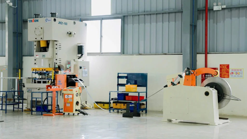
Automated coil feeding systems deliver continuous raw material into automotive metal stamping presses
17.4.1 Experience serving US/EU automotive buyers
Verify a proven track record of exporting stamped components to North America and Europe, ensuring clear technical communication, milestone management, and schedule adherence.
17.4.2 Export documentation capability
Ensure the supplier provides complete export compliance documentation, including Mill Test Reports (MTR), CMM dimensional verification data, and Certificates of Conformance.
17.4.3 Packaging and logistics capability
Confirm that parts are protected using Vapor Corrosion Inhibitor (VCI) bags, custom returnable dunnage, and ocean-freight palletizing to prevent transport rust or physical handling damage.
17.4.4 Communication and RFQ response speed
Prompt technical communication, structured engineering proposals, and fast RFQ turnaround times are key indicators of a professional contract manufacturing partner.
18. Automotive Metal Stamping RFQ Process
18.1 How to request an automotive stamping quote
18.1.1 Submit 2D drawings and 3D CAD files
Provide STEP or IGES 3D CAD models for geometry analysis, along with detailed 2D PDF technical drawings indicating critical tolerances, hole centers, thread callouts, and GD&T requirements.
18.1.2 Provide material, thickness, tolerance, and annual volume
Explicitly define raw material specifications (such as ASTM, EN, or JIS alloy designations), sheet thickness, allowable dimensional tolerances, and projected annual production volumes.
18.1.3 Specify surface finish, welding, and assembly requirements
State all required secondary processes upfront including vibratory deburring, zinc plating, E-coating, spot welding, or self-clinching fastener installation.
18.2 Engineering review process
18.2.1 Tooling feasibility analysis
Engineers analyze 3D models using forming simulation software to evaluate material stretch limits, draw depths, internal corner radii, and springback risks, determining whether progressive or transfer tooling is required.
18.2.2 Stamping process planning
Manufacturing teams map out the complete operational sequence from raw coil decoiling and strip punching to secondary cleaning, plating, and final quality inspection.
18.2.3 Cost and lead time estimation
Based on press cycle speeds, raw material tonnage, tooling fabrication hours, and quality checks, suppliers issue transparent piece-price quotations and tooling delivery schedules.
18.2.4 Quality requirement review
Quality teams verify required compliance deliverables such as Level 3 PPAP packages, special checking fixtures, or automated optical inspection gates.
18.3 What buyers should prepare
18.3.1 Technical drawings and CAD files
Fully dimensioned technical drawings with clean line geometry allow toolmakers to accurately calculate punch clearances, press tonnage requirements, and strip progressions.
18.3.2 Annual volume forecast
Providing prototype requirements alongside 1-year and 3-year production forecasts helps suppliers recommend optimal tooling strategies and volume-tiered piece pricing.

In-die sensors protect tooling and track dynamic loads during continuous automotive metal stamping
18.3.3 PPAP or inspection requirements
Define required quality deliverables upfront such as First Article Inspection (FAI) reports, CMM measurement logs, or full Level 3 PPAP submission packages.
18.3.4 Packaging and delivery requirements
Specify custom packaging needs, such as VCI anti-rust wrapping, individual carton labeling, or returnable plastic dunnage trays suitable for automated assembly lines.
18.4 Faster RFQ best practices
18.4.1 Define critical dimensions clearly
Distinguish critical functional mating dimensions from general non-critical features. Avoid applying unnecessarily tight tolerances across non-functional part edges to prevent excess tooling costs.
18.4.2 Specify material grade and thickness
Specify standard ASTM, EN, or JIS material grades to help suppliers immediately verify local raw coil availability and current market steel pricing.
18.4.3 Clarify production volume and program timeline
Disclosing prototype timelines alongside long-term mass production forecasts allows suppliers to propose optimal tooling strategies and volume-tiered pricing structures right from the initial quote.
18.4.4 Share supplier audit requirements early
Sharing corporate quality audit guidelines and packaging criteria early in the quoting process prevents technical misunderstandings and shortens project kick-off lead times.
19. Trusted Automotive Metal Stamping Supplier in Vietnam – Automech
19.1 Automech automotive metal stamping capability
19.1.1 Automotive metal stamping for OEM components
Established in 2020, Automech (Automech Mechanical Equipment and Solutions Joint Stock Company) provides comprehensive automotive metal stamping services for OEM and Tier 1 customers. The company manufactures structural, chassis, and body components conforming to international automotive standards.
19.1.2 Sheet metal stamping capability
Automech operates modern mechanical, hydraulic, and servo press machinery to process flat sheets and coils into durable brackets, covers, and structural panels. Flexible press lines accommodate diverse automotive part geometries with high efficiency.
19.1.3 Precision metal stamping support
Automech delivers precision metal stamping solutions with micro-level tolerance control and zero-burr edge quality. Advanced press systems and rigid die sets produce tight-tolerance components for vehicle electronics and powertrain assemblies.
19.1.4 Progressive die stamping capability
Capitalizing on high-speed automated press lines, Automech designs and operates progressive die systems that execute continuous piercing, bending, and forming in single tool sets for high-volume automotive orders.
19.2 Tooling and engineering support
19.2.1 Metal stamping tooling support
Automech offers turnkey tool and die support. Factory 1 in Bac Ninh (10,500 m²) features dedicated tooling areas, CNC machining centers, wire EDM machines, and tryout presses for die manufacturing.
19.2.2 Tool and die design support
Automech’s in-house engineering and R&D team designs and manufactures cold stamping dies, welding jigs, assembly fixtures, and inspection gauges tailored to complex customer CAD models.
19.2.3 Tooling feasibility review
Before hardening die components, Automech conducts thorough DFM and tool feasibility reviews to analyze metal stretch, springback compensation, and press tonnage distribution, ensuring smooth mass production launch.
19.3 Automotive stamped parts capability

Automotive metal stamping manufactures rigid motor mounts that absorb heavy road vibrations consistently
19.3.1 OEM metal stamping parts
Automech has demonstrated proven execution capabilities across major industrial projects for leading enterprises such as VinFast, VinES, Hoa Phat, Kim Long Motors, and Seojin. The company produces precision drivetrain components, brackets, and structural subassemblies.
19.3.2 Automotive sheet metal parts
Automech produces automotive structural sheet metal components, electric bus frame structures, interior panels, and body reinforcements. Factory 2 (10,000 m², inaugurated June 2026) is dedicated to high-volume automotive component manufacturing with an 80% target automation rate.
19.3.3 Automotive bracket stamping
Automech manufactures motor mounts, suspension brackets, sensor holders, and chassis gussets. Multi-station stamping dies yield precise hole patterns and formed flange angles across mass batches.
19.3.4 Automotive stamping assembly
Automech integrates individual stamped parts into complete automotive sub-assemblies. The company combines progressive press stamping with automated welding, riveting, and fastener insertion.
19.4 Welding and assembly capability
19.4.1 Stamped part welding
Automech integrates robotic welding cells, spot welding stations, laser welding, and ultrasonic welding systems. Applications include automated 800-1300 ton tandem stamping lines with ABB robots and electric bus frame welding with KUKA robots and Fronius power sources.
19.4.2 Fixture-controlled assembly
To ensure zero-clearance fitment, Automech builds precision welding jigs and inspection fixtures (Jigs) in-house. Custom clamping fixtures align stamped parts accurately during robotic joining.
19.4.3 Dimensional validation for assemblies
Completed welded sub-assemblies undergo dimensional validation using dedicated attribute checking fixtures and Coordinate Measuring Machines (CMM) to verify overall geometry against OEM drawing requirements.
19.5 Quality and inspection systems
19.5.1 CMM inspection
Automech utilizes Coordinate Measuring Machines (CMM) and optical measuring systems in climate-controlled laboratories (~ 20 °C). Dimensional checks validate complex GD&T parameters directly against customer CAD models.
19.5.2 Gauge inspection
Custom attribute checking fixtures and hard receiver gauges provide rapid 100% feature verification for high-volume automotive components on active production lines.
19.5.3 First article inspection
Strict quality protocols require complete First Article Inspection (FAI) approval before launching mass production press runs. Inspectors verify all drawing dimensions, form angles, and hole locations.
19.5.4 In-process quality control
Quality control is embedded across all manufacturing stages. Statistical sampling, in-die sensor monitoring, and automated vision checks track part dimensions to maintain process stability.
19.5.5 Traceability and QA documentation
Automech provides complete quality documentation packages including material certificates, heat treatment logs, CMM dimensional reports, and batch traceability data required by global OEM auditors.
19.6 Export manufacturing capability

First article inspection validates tool alignment before starting full-scale automotive metal stamping runs
19.6.1 Experience serving US/EU buyers
Automech’s modern production facilities and engineering systems are structured to serve international Tier 1 and OEM buyers across North America, Europe, and Asia. The engineering team adheres to international standards and B2B project management practices.
19.6.2 Export-ready production and documentation
Automech prepares export orders with protective VCI anti-rust packaging, wooden palletizing, clear shipping labels, and comprehensive customs clearance documentation.
19.6.3 OEM and Tier supplier support
Automech provides full-lifecycle support for international automotive buyers, delivering prompt DFM reviews, reliable trial tryouts, and volume mass production backed by nationwide technical service hubs in Hanoi, Bac Ninh, Hai Phong, Da Nang, Hue, and Ho Chi Minh City.
20. AI Overview & Featured Snippet Section
20.1 People Also Asked questions
20.1.1 What is automotive metal stamping?
Automotive metal stamping is a high-speed cold-forming manufacturing process that uses mechanical or hydraulic presses equipped with custom-engineered dies to shape sheet metal coils into precision vehicle components, including structural brackets, body panels, and chassis reinforcements.
20.1.2 What parts are made by automotive metal stamping?
Automotive stamping produces body-in-white (BIW) panels, floor pans, B-pillar reinforcements, bumper crash boxes, chassis suspension brackets, motor mounting plates, EV battery tray structures, seat rails, and protective heat shield covers.
20.1.3 What materials are used in automotive metal stamping?
Common materials include commercial low-carbon cold-rolled steel (SPCC), high-strength low-alloy (HSLA) steel, advanced high-strength steel (AHSS, Dual-Phase), austenitic/ferritic stainless steel (SUS304, SUS409), structural aluminum alloys (5052, 6061), and galvanized steel.
20.1.4 What is progressive die stamping in automotive manufacturing?
Progressive die stamping is an automated method that advances a continuous coiled strip through sequential cutting, piercing, bending, and forming stations mounted within a single die block, completing a finished automotive component at high speeds with every press stroke.
20.1.5 How do I choose an automotive metal stamping supplier?
Select an automotive stamping supplier based on press tonnage range (100T to 1,300T+), in-house toolroom and wire EDM capabilities, active IATF 16949 certification, full Level 3 PPAP submission readiness, robotic welding integration, and proven export packaging experience.
20.1.6 How do I request an automotive metal stamping RFQ?
To request an RFQ, provide 3D CAD models (STEP/IGES) and 2D engineering drawings (PDF) detailing critical tolerances, hole locations, and GD&T datums. Specify raw material alloy grades, sheet thickness, required surface finishes, annual production volumes, and delivery timelines.
20.1.7 Why source automotive metal stamping from Vietnam?
Vietnam offers competitive production costs, an expanding network of modern high-tonnage press facilities, skilled toolmaking talent, and strong export readiness. It serves as a prime “China+1” supply chain diversification destination for North American and European automotive buyers.
20.2 Short answer blocks
20.2.1 Automotive metal stamping definition
Automotive metal stamping is an automated pressworking process that transforms flat sheet metal into custom vehicle components using matched die sets. The technology delivers high dimensional precision, structural crash energy resistance, and low unit costs for mass-production vehicle platforms.
20.2.2 Common automotive stamped parts summary
Key automotive stamped parts include chassis mounting brackets, structural body-in-white crossmembers, door intrusion beams, B-pillar stiffeners, EV battery enclosures, and protective splash covers manufactured from high-strength steel and lightweight aluminum alloys.
20.2.3 Automotive metal stamping supplier selection summary
Selecting a reliable contract automotive stamping supplier requires verifying press machine tonnage capacity, in-house progressive and transfer die engineering, certified IATF 16949 quality management, CMM dimensional verification labs, and established B2B export logistics management.

Level 3 PPAP documentation proves manufacturing capability for OEM automotive metal stamping programs
20.3 Featured snippet opportunities
20.3.1 Definition snippet: What is automotive metal stamping?
Automotive metal stamping is a precision manufacturing process that uses high-tonnage stamping presses and custom-engineered dies to cold-form sheet metal into finished vehicle parts. Operations include blanking, piercing, bending, forming, and drawing to mass-produce structural chassis components, body panels, and mounting brackets with tight tolerance repeatability.
20.3.2 List snippet: Common automotive stamped parts
The most common automotive stamped parts include:
- Structural BIW Parts: B-pillar reinforcements, roof headers, floor crossmembers.
- Chassis & Mounts: Heavy engine brackets, suspension gussets, control arm links.
- Safety Components: Bumper beams, door intrusion bars, crash boxes.
- EV Powertrain Parts: Battery pack trays, module tie rods, busbar connectors.
- Protective Covers: Splash shields, oil pan covers, exhaust heat shields.
20.3.3 Table snippet: Progressive die stamping vs transfer stamping
| Feature | Progressive Die Stamping | Transfer Stamping |
| Material Input | Continuous coiled strip carrier | Pre-cut discrete blanks |
| Part Movement | Strip pulled/pushed through die stations | Mechanical grippers or shuttle bars |
| Production Speed | 100 to 500+ parts per minute | 15 to 40 parts per minute |
| Maximum Part Size | Small-to-midsize structural components | Large structural panels and deep shells |
| Material Scrap | Higher (Carrier ribbon scrap skeleton) | Lower (Optimized blank nesting) |
| Target Volume | High volume (> 50,000 parts/year) | Medium to high volume (20,000+ parts/year) |
20.3.4 Checklist snippet: How to choose an automotive metal stamping supplier
When selecting an automotive metal stamping supplier, buyers should verify the following capabilities:
- Press Equipment Fleet: Mechanical, hydraulic, and tandem press lines ranging from 100 to 1,300+ tons.
- Toolroom Assets: In-house CAD/CAM die design, wire EDM machining, and preventive die maintenance.
- Quality Standards: Active IATF 16949 and ISO 9001 certifications with full Level 3 PPAP submission capability.
- Assembly Integration: In-house robotic spot/MIG welding, self-clinching fastener insertion, and surface plating.
- Export Readiness: Experience serving US/EU buyers, VCI anti-corrosion packaging, and complete customs documentation.
20.3.5 Process snippet: Automotive metal stamping process steps
The automotive metal stamping process follows five primary steps:
- Engineering & DFM Review: CAD model validation, bend radius analysis, and forming simulation.
- Tooling & Die Fabrication: CNC milling, vacuum heat treatment, and precision wire EDM die machining.
- Material Preparation: Uncoiling, roll-leveling, and automated servo strip feeding.
- Press Stamping Operations: Shearing, punching, bending, drawing, and in-die sensing.
- Quality Inspection & Finishing: CMM dimensional verification, deburring, plating, and VCI packaging.
21. Internal Linking Strategy
21.1 Parent service link
21.1.1 Metal stamping services
Explore our comprehensive [Metal Stamping Services] pillar page to understand the broader capabilities of cold-forming manufacturing, pressworking technologies, and turnkey tooling solutions for global industrial supply chains.
21.2 Metal stamping cluster links
21.2.1 Sheet metal stamping
Explore our guide on [Sheet Metal Stamping] to understand single-operation press capabilities, material gauge selection, and economical forming solutions for short-run industrial parts.
21.2.2 Precision metal stamping
Learn about micro-tolerance capabilities, tungsten carbide die insert applications, and zero-burr edge quality standards on our [Precision Metal Stamping] cluster page.
21.2.3 Progressive die stamping
Review continuous coil-feeding workflows, stroke speed optimization, and multi-station tooling advantages in our detailed [Progressive Die Stamping] guide.
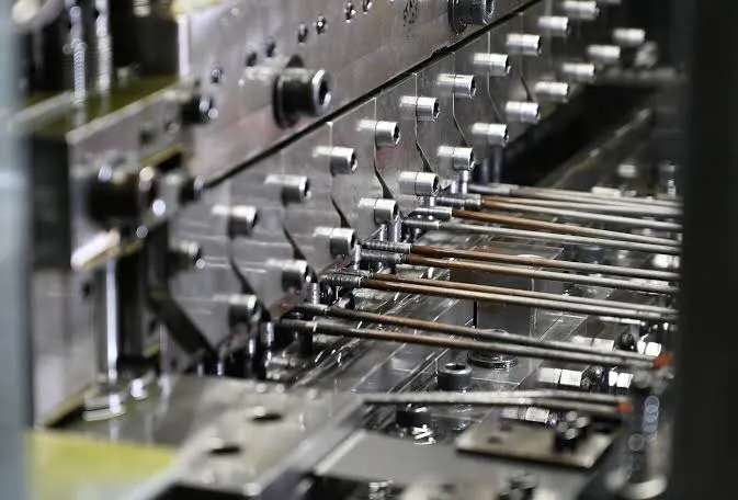
Transfer press automation enables automotive metal stamping for large structural body side panels
21.2.4 Metal stamping tooling
Understand die steel selection, springback compensation design, and preventive toolroom maintenance by reading our technical guide on [Metal Stamping Tooling].
21.3 Automotive stamping links
21.3.1 Automotive bracket stamping
See how high-speed stamping presses process thick-gauge carbon steel into rigid engine mounts, chassis gussets, and sensor brackets on our [Automotive Bracket Stamping] page.
21.3.2 Automotive stamping assembly
Explore integrated manufacturing workflows combining press forming with robotic spot welding, riveting, and automated hardware insertion on our [Automotive Stamping Assembly] resource.
21.3.3 RFQ automotive stamping supplier
Streamline your procurement timeline by accessing our step-by-step submission checklist and technical drawing requirements at [RFQ Automotive Stamping Supplier].
21.4 Supplier and sourcing links
21.4.1 Automotive stamping supplier Vietnam for US
Discover how Vietnamese contract manufacturers comply with US engineering standards, tariff regulations, and transoceanic shipping protocols at [Automotive Stamping Supplier Vietnam for US].
21.4.2 Automotive stamping supplier Vietnam for Europe
Learn about VCI anti-rust packaging, EN material standards, and Euro-centric quality compliance on our page for [Automotive Stamping Supplier Vietnam for Europe].
21.4.3 Alternative China stamping supplier
Examine supply chain resilience, risk mitigation, and dual-sourcing benefits in our strategic report on [Alternative China Stamping Supplier].
21.4.4 Automotive export stamping manufacturer
Understand international shipping protocols, protective VCI packaging, customs documentation, and logistics management by visiting our page on [Automotive Export Stamping Manufacturer].
21.4.5 Automotive stamping OEM sourcing
Learn how global OEMs partner with contract stamping facilities to scale vehicle platform production on our [Automotive Stamping OEM Sourcing] resource.
21.5 Related manufacturing links
21.5.1 Tool and die export manufacturer
Review in-house toolroom capabilities, CNC/wire EDM machining, and export die trial validation at [Tool and Die Export Manufacturer].
21.5.2 Automotive progressive die supplier Vietnam
Explore custom multi-station progressive die design and high-volume press production capabilities at [Automotive Progressive Die Supplier Vietnam].
21.5.3 BIW automotive manufacturer Vietnam
Learn how advanced stamping, 3D pipe bending, and robotic welding support vehicle body structures at [BIW Automotive Manufacturer Vietnam].
22. Conversion Section: Request Automotive Metal Stamping RFQ
22.1 Why global automotive buyers choose reliable stamping suppliers
22.1.1 Lower production risk
Partnering with an experienced contract automotive metal stamping supplier mitigates production risks through standardized tool design, in-die sensor monitoring, and structured quality management systems. Standardized procedures prevent non-conforming parts from reaching customer assembly lines, eliminating costly downtime for global OEMs.
22.1.2 Better dimensional consistency
High-precision press systems equipped with rigid die shoes and precision guide pins ensure identical feature locations across millions of press cycles. Dimensional consistency simplifies automated robotic assembly and eliminates line fitment issues across complex vehicle body and chassis modules.
22.1.3 Stronger tooling and quality control
Professional stamping partners maintain dedicated toolrooms for scheduled die inspection, punch regrinding, and preventive maintenance. In-house CMM laboratories and Level 3 PPAP documentation provide complete transparency and batch-to-batch traceability.
22.1.4 Better support for OEM audit requirements
Certified stamping manufacturers operate under IATF 16949 systems that maintain comprehensive audit readiness. Full digital records of material heat lots, machine parameters, and calibration logs ensure smooth supplier quality audits and long-term compliance.
22.2 RFQ CTA strategy
22.2.1 Request RFQ
Initiate your project quotation today by submitting your component requirements through our online portal to receive a detailed piece-price and tooling estimate from our automotive engineering team.
22.2.2 Upload technical drawings
Share your 3D CAD models (STEP, IGES) alongside 2D PDF technical drawings with fully defined tolerances, material specifications, and surface finish callouts for instant engineering review.

Automotive metal stamping minimizes piece-part costs through optimized strip layout and nesting designs
22.2.3 Contact automotive engineering team
Connect directly with Automech’s toolmakers and automotive engineers to discuss custom die configurations, alloy formability, press tonnage demands, and production scheduling.
22.2.4 Request tooling feasibility review
Obtain an upfront tooling feasibility assessment analyzing strip stretch limits, springback behavior, punch clearances, and tonnage distribution prior to capital commitment.
22.2.5 Request stamping cost analysis
Request a comprehensive cost optimization analysis evaluating coil nesting layouts, material utilization rates, and progressive vs transfer die economics.
22.2.6 Request supplier audit information
Request our complete supplier audit package, including ISO 9001 and IATF 16949 certificates, factory equipment lists, and past OEM project references.
22.2.7 Get automotive metal stamping quotation
Contact Automech today to receive a competitive, volume-tiered quotation for prototype development, pre-series runs, or mass-production automotive metal stamping projects in Vietnam.
23. FAQ Section
23.1 What is automotive metal stamping?
23.1.1 Automotive metal stamping is a manufacturing process that uses presses and dies to form sheet metal into vehicle components.
Automotive metal stamping is an automated cold-forming manufacturing operation where mechanical or hydraulic press machines drive custom-engineered tool and die sets into flat sheet metal stock. The process executes blanking, piercing, bending, forming, and drawing operations to produce durable, high-precision structural and exterior vehicle components with rapid cycle times.
23.2 What parts are made by automotive metal stamping?
23.2.1 Common stamped parts include brackets, reinforcement plates, covers, mounting parts, structural supports, and body-related components.
Automotive stamping manufactures key components including body-in-white (BIW) panels, door reinforcements, B-pillar stiffeners, bumper crash boxes, engine mounting brackets, chassis suspension links, EV battery pack enclosures, seat frame components, and exhaust heat shields.
23.3 What materials are used in automotive metal stamping?
23.3.1 Common materials include carbon steel, stainless steel, aluminum, galvanized steel, and high-strength steel.
Contract stamping facilities process cold-rolled carbon steel (SPCC), drawing-quality steel (SPCE), high-strength low-alloy (HSLA) steel, advanced high-strength steel (AHSS, Dual-Phase), austenitic and ferritic stainless steel (SUS304, SUS409), structural aluminum alloys (5052, 6061-T4/T6), and electro-/hot-dip galvanized steel.
23.4 What is progressive die stamping in automotive manufacturing?
23.4.1 Progressive die stamping uses multiple stations in one die to perform cutting, bending, and forming operations for high-volume parts.
Progressive die stamping is an automated high-speed method that feeds a continuous metal strip through sequential inline stations within a single die block. Each stroke performs distinct cutting, piercing, and forming operations concurrently while the strip advances, producing completed automotive components at the final cutoff station at rates of 100 to 500+ parts per minute.
23.5 How do I request an automotive metal stamping RFQ?
23.5.1 Submit CAD files, technical drawings, material specifications, thickness, tolerance, annual volume, surface finish, and quality requirements.
To receive an accurate quotation, submit your 3D CAD files (STEP/IGES) and 2D engineering drawings (PDF) detailing critical tolerances and GD&T datums. Specify exact raw material grades, sheet thickness, required surface treatments, secondary welding or assembly requirements, annual volume forecasts, and quality documentation requirements (such as Level 3 PPAP).
Automech Mechanical Equipment and Solutions Joint Stock Company
Head Office: No. 285 Phuc Loi Street, Phuc Loi Ward, Hanoi City
Da Nang Branch: No. 20 Nguyen Sinh Sac Street, Hoa Khanh Ward, Da Nang City
Ho Chi Minh Branch: No. 84, Street No. 10, Van Phuc Urban Area, Hiep Binh Ward, Ho Chi Minh City
Factory No. 1: Automech Automation Equipment, Mold & Tool Manufacturing Factory – Automech Demo Center: Dinh Tram Industrial Park, Nenh Ward, Bac Ninh City, Vietnam
Factory No. 2: Automech Parts Manufacturing & Component Fabrication Factory: Viet Nhat Industrial Cluster, Xuan Cam Commune, Bac Ninh City, Vietnam
Hotline: 0987 899 347
Website: https://automechmfg.com/
Fanpage: https://www.facebook.com/automech.mfg/
YouTube: https://www.youtube.com/@Automechmfg