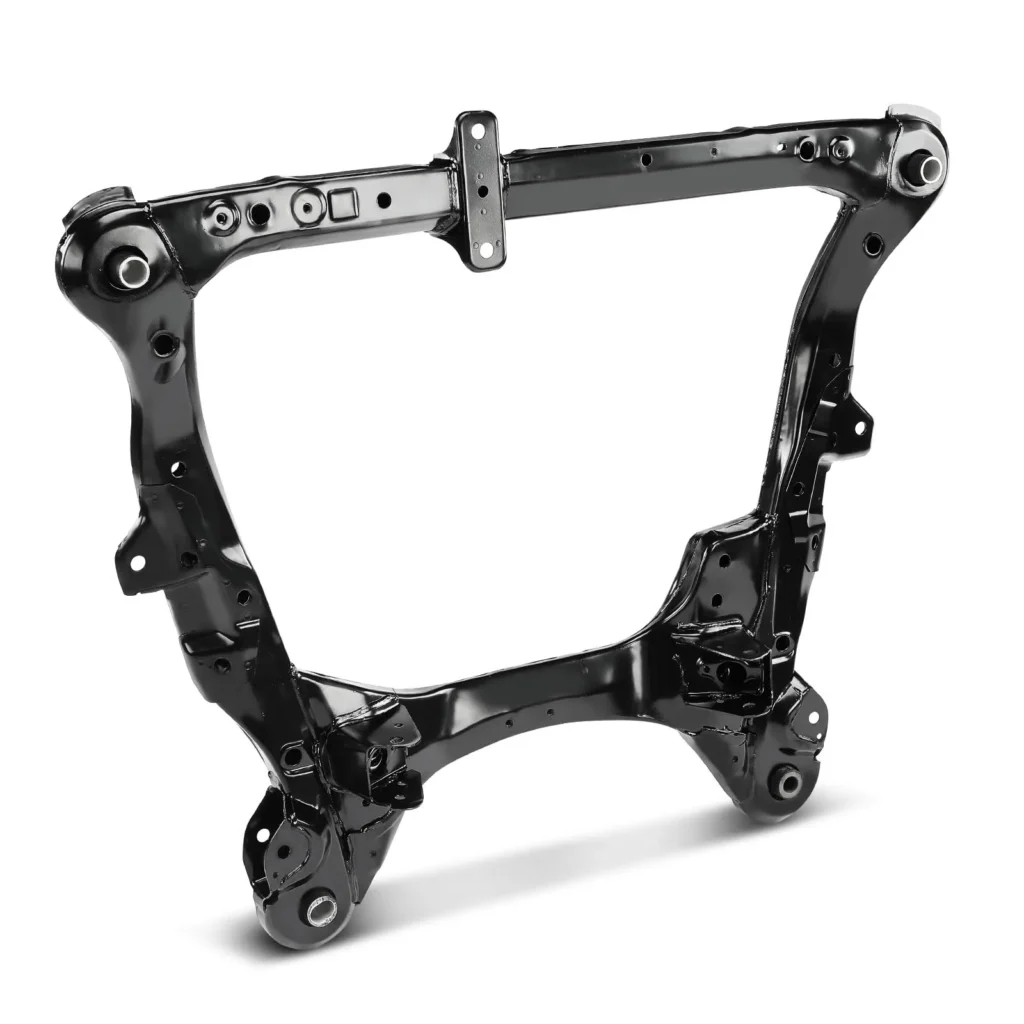
In the rapidly evolving global automotive supply chain, original equipment manufacturers (OEMs) and Tier-1 suppliers are continuously optimizing their sourcing strategies for critical structural components. As the Body in White (BIW) architecture undergoes revolutionary shifts due to electrification and stringent crash safety regulations, finding a highly competent cross car beam manufacturer has become a top priority. This comprehensive technical guide analyzes the engineering, manufacturing processes, quality frameworks, and geopolitical advantages of sourcing cross car beams from Vietnam, highlighting how Automech delivers world-class automotive structural solutions.
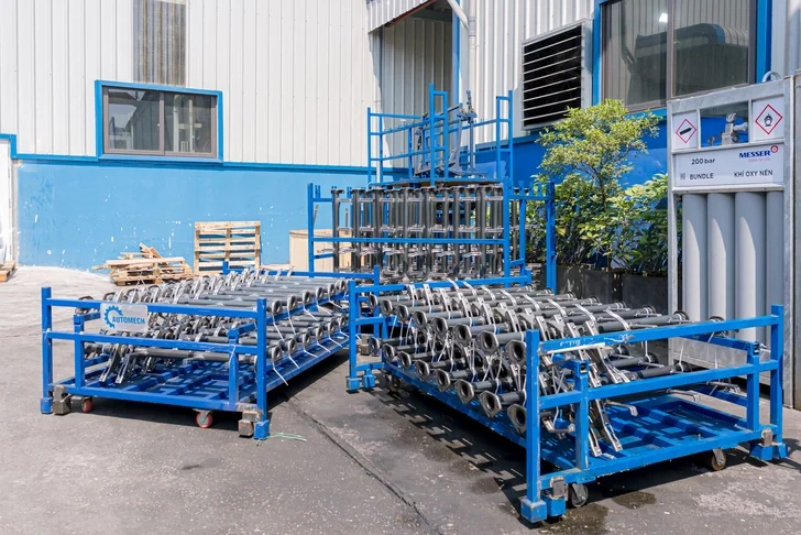
Batches of automotive steel pipes manufactured in-house at Automech.
1. Introduction: Growing Demand for Cross Car Beam Manufacturers
1.1 Evolution of automotive body structure manufacturing
1.1.1 Increasing demand for lightweight vehicle structures
The modern automotive industry is driven by the urgent need to reduce vehicle emissions and improve energy efficiency. In traditional internal combustion engine (ICE) vehicles, reducing weight directly correlates with lower carbon dioxide emissions. For modern automotive structural engineering, this has forced a complete re-engineering of the Body in White (BIW) platform. Manufacturers are shifting away from heavy, low-carbon mild steels toward advanced materials that offer high tensile strength at a fraction of the weight, putting immense technical pressure on the cross car beam manufacturer to adapt their production lines.
1.1.2 Growth of EV and safety-focused vehicle platforms
The exponential rise of Electric Vehicles (EVs) has accelerated the demand for structural weight optimization. EVs carry heavy battery packs, which increases the total vehicular mass and alters the center of gravity. To maintain driving range and ensure passive safety during collision events, EV architectures require highly rigid, energy-absorbing cabin structures. The cross car beam acts as a primary defense vector in lateral and frontal crashes, forcing manufacturers to design complex, multi-material cross car beam assemblies that protect occupants and fragile battery systems simultaneously.
1.2 Why OEMs are searching for cross car beam manufacturers
1.2.1 Demand for BIW structural component suppliers
Global automotive OEMs are facing capacity constraints and rising labor costs in traditional manufacturing hubs. To maintain competitive cost structures, procurement teams are actively seeking specialized Tier-1 or Tier-2 suppliers capable of handling complex Body in White (BIW) structural components. A reliable cross car beam manufacturer must not only possess raw production capacity but also deeply understand structural integration, metal forming limits, and the strict engineering tolerances required for modern vehicle cabins.
1.2.2 Need for high-precision automotive welding assembly
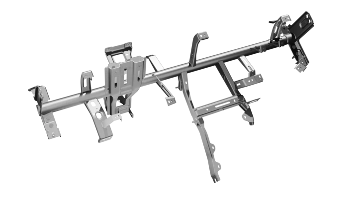
A cross car beam is rarely a single piece of formed metal; it is a complex, multi-component assembly comprising brackets, steering column supports, airbag housings, and HVAC mounts. Joining these heterogeneous parts requires absolute precision. OEMs look for manufacturers who have heavily invested in automated, high-precision automotive welding assembly systems. Even a microscopic deviation in weld quality or dimensional positioning can misalign the entire dashboard, steering system, or pedal box, disrupting the OEM’s main assembly line.
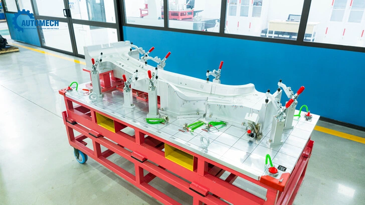
High-precision manufacturing jig for automotive parts at Automech factory.
2. What is a Cross Car Beam? (Featured Snippet Definition)
2.1 Definition of cross car beam in automotive engineering
2.1.1 Structural component supporting dashboard systems
In automotive engineering, a cross car beam (CCB) is a high-strength structural lateral member that spans the entire width of the vehicle cabin, positioned directly underneath the dashboard assembly. It serves as the primary mechanical backbone of the cockpit area. Every major component in front of the driver and passenger—including the instrument cluster, center console, glove box, passenger airbag module, and climate control (HVAC) units—is physically bolted to or suspended from this high-strength beam structure.
2.1.2 Critical reinforcement member in vehicle cabin structure
Beyond its role as a component carrier, the cross car beam is a vital safety asset integrated into the vehicle’s structural safety cage. It bridges the left and right sides of the vehicle’s body structure. By acting as a rigid cross-brace, the cross car beam prevents the cabin from collapsing inward during severe side-impact collisions or rollover accidents, absorbing and distributing kinetic impact energy away from the vehicle occupants.
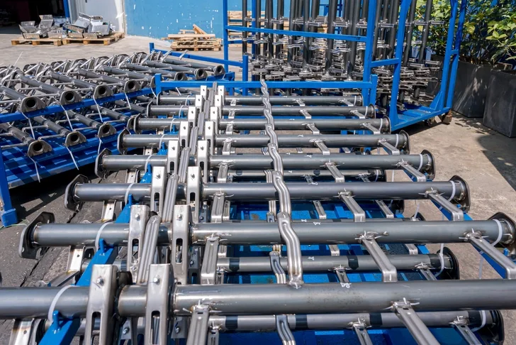
Close-up of cross car beam components after professional laser cutting and tube bending at Automech.
2.2 Function of automotive cross car beam
2.2.1 Structural rigidity and crash performance
The primary mechanical function of an automotive cross car beam is to maximize the torsional and lateral stiffness of the front cabin zone. During a side-impact collision (such as an IIHS or Euro NCAP side pole test), the cross car beam works in tandem with the A-pillars and door intrusion beams. It transfers the localized impact forces across the vehicle width to the opposite side of the chassis, minimizing passenger compartment intrusion and safeguarding human lives.
2.2.2 Integration of steering and dashboard systems
The cross car beam must provide an exceptionally stable, vibration-free mounting platform for the steering column assembly. Because the steering system is subjected to high dynamic forces from the road and the driver’s input, the cross car beam’s steering brackets must exhibit zero structural play. Additionally, the beam stabilizes the expansive instrument panel sheet, eliminating squeaks, rattles, and unwanted tactile feedback through the steering wheel.
2.3 Role of cross car beam in BIW assembly
2.3.1 Connection with A-pillar and B-pillar structures
During the Body in White (BIW) assembly phase, the cross car beam is securely bolted or welded to the inner structures of both the left and right A-pillars. This structural connection forms a rigid closed loop with the front bulkhead, cowl panel, and floor pan. This strategic positioning establishes a continuous load path that links the lower chassis frames to the upper roof rails, enhancing the overall structural integrity of the vehicle.
2.3.2 Contribution to NVH and safety performance
Noise, Vibration, and Harshness (NVH) mitigation is a core benchmark of modern vehicle quality. A poorly designed or sub-optimally manufactured cross car beam will resonate at frequencies generated by the engine, transmission, or road surface, leading to cabin noise. By engineering the cross car beam to have high natural frequencies, the cross car beam manufacturer ensures that the component suppresses structural vibrations, directly improving cabin quietness while meeting global automotive crash safety compliance standards.
3. Cross Car Beam Manufacturing Process
3.1 Overview of cross car beam production workflow
3.1.1 Material preparation and blanking
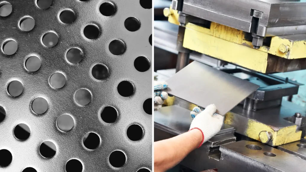
The manufacturing cycle begins with strict material inspection and preparation. High-strength steel or aluminum coils are loaded onto automated decoiling lines. The metal sheets pass through straighteners to eliminate residual coil set stresses before entering the high-speed blanking press. Here, precision dies cut the continuous sheet into optimized, flat geometric blanks designed to minimize material scrap rates during subsequent forming operations.
3.1.2 Stamping, welding, and assembly stages
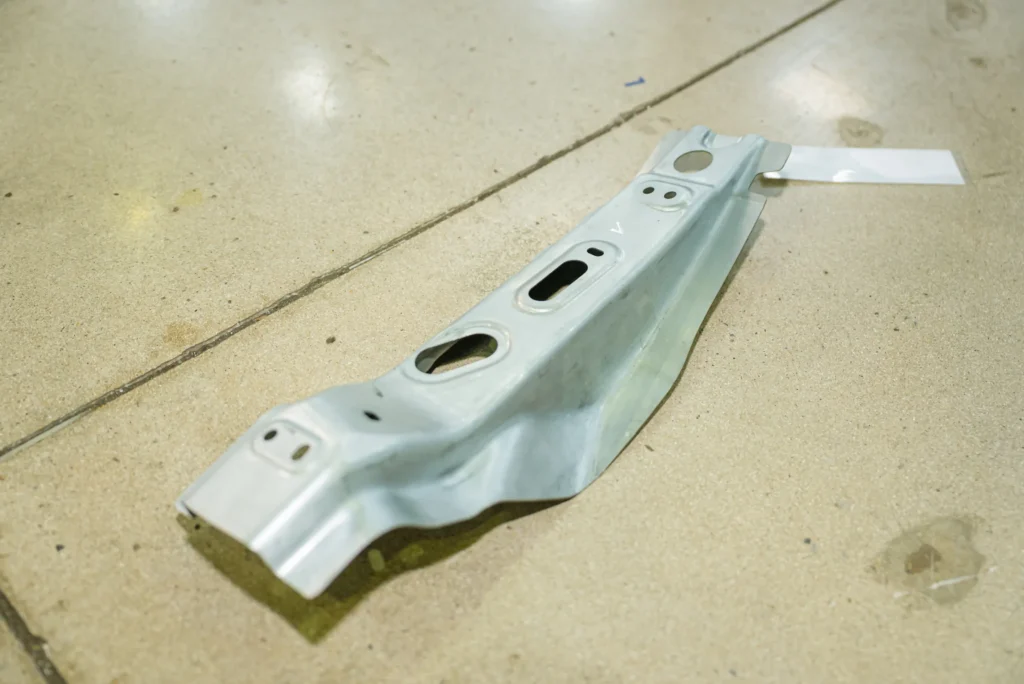
Once the blanks are prepared, they are transferred to the primary stamping line to undergo heavy cold forming or progressive drawing. After individual stamped parts (the main tube, side plates, reinforcement channels, and dozens of unique utility brackets) are produced, they enter the automated welding shop. In this stage, robotic cells manipulate, clamp, and fuse the components into a singular, unified cross car beam assembly, followed by surface coating and rigorous metric verification.
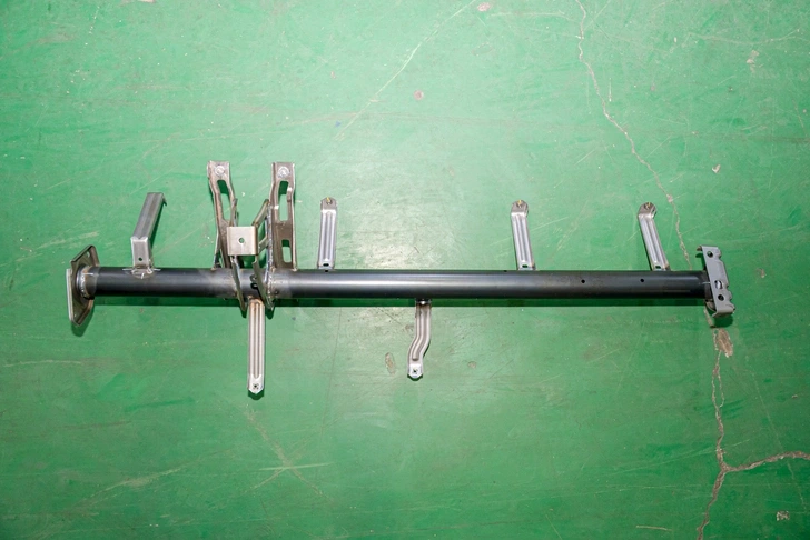
In-house fabricated automotive steel beam component by Automech, a professional cross car beam manufacturer
3.2 Automotive cross car beam stamping process
3.2.1 Progressive die stamping technology
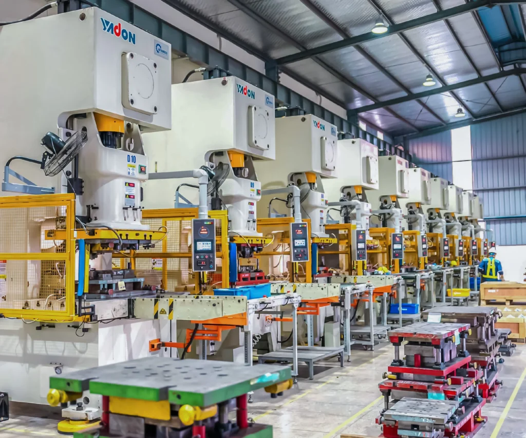
For high-volume automotive platforms, progressive die stamping is the industry standard for bracket and reinforcement production. The blanked material is fed through a continuous, multi-station tool housed within a single massive press. At each stroke of the press, the material moves sequentially to the next station to undergo piercing, bending, flanging, and drawing. This integrated process ensures high repeatability, rapid cycle times, and exceptionally low labor costs per part.
3.2.2 High-tonnage stamping systems
The main tube or backbone of a cross car beam often requires heavy-gauge steel or advanced alloys that resist deformation. To form these demanding geometries without causing structural cracking or springback defects, a professional cross car beam manufacturer utilizes high-tonnage stamping systems ranging from 800 to 2,500 tons. These massive hydraulic or servo-driven presses exert controlled, immense pressure over precise depth profiles to achieve the exact geometric contours required by OEM engineering blueprints.
3.3 Cross car beam welding assembly
3.3.1 Robotic MIG/TIG welding systems
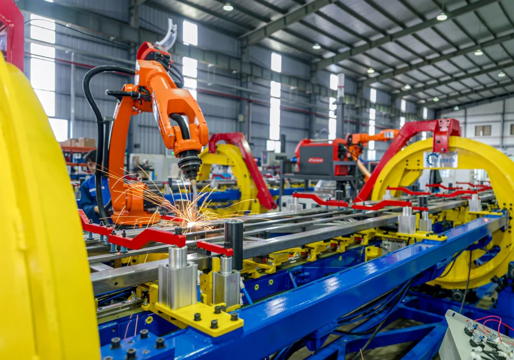
Given the safety-critical nature of the cross car beam, manual welding is insufficient for mass production. Multi-axis robotic arms equipped with advanced Metal Inert Gas (MIG) or Tungsten Inert Gas (TIG) welding torches are deployed. These robots follow synchronized, pre-programmed paths to apply continuous, uniform weld beads along the joints connecting the main beam to the heavy steering column mounts, ensuring flawless thermal penetration and structural fusion.
3.3.2 Spot welding and fixture integration
In addition to continuous arc welding, automated resistance spot welding is heavily utilized to secure smaller positioning brackets and wire-harness clips. The individual components are dropped into heavy-duty pneumatic welding fixtures. These custom-engineered jigs utilize proximity sensors and mechanical toggle clamps to hold every sub-component locked in place at exact spatial coordinates, preventing thermal warping or dimensional distortion during the intense heat of the welding cycles.
3.4 Surface finishing and inspection
3.4.1 Anti-corrosion treatment
Because the cross car beam is concealed within the dashboard environment, it must be protected against long-term environmental degradation, moisture condensation from the HVAC units, and localized humidity. Completed assemblies undergo automated multi-stage chemical cleaning, phosphating, and Cathodic Electrodeposition (CED/E-coating). This process bakes a highly durable, anti-corrosive epoxy layer over every square millimeter of internal and external metal surfaces.
3.4.2 Dimensional validation process
Immediately following surface finishing, parts are routed to the quality lab for dimensional validation. Technicians subject the cross car beams to automated tactile probes and optical scanners. Any part displaying a spatial variance beyond the strict sub-millimeter limits specified by the automotive client is flagged for quarantine, ensuring that zero out-of-tolerance components reach the vehicle integration plant.
4. Materials Used in Cross Car Beam Production
4.1 Steel materials for automotive structural parts
4.1.1 High-strength steel (HSS)
High-Strength Steel (HSS) has long been the foundational workhorse for a cross car beam manufacturer. Grades like HSS 340 or 420 provide an optimal balance between yield strength, formability, and cost-efficiency. They offer the necessary structural rigidity to handle day-to-day cabin loads and steering column stresses while remaining easy to form using standard mechanical stamping presses without inducing excessive tooling wear.
4.1.2 Advanced high-strength steel (AHSS)
To achieve aggressive weight reduction without compromising crash safety, modern cross car beam manufacturers utilize Advanced High-Strength Steel (AHSS), including Dual-Phase (DP) steels, Complex-Phase (CP) steels, and Martensitic steels (MS) with tensile strengths exceeding 1000 MPa. These micro-alloyed steels allow for much thinner material gauges to be used while maintaining superior energy absorption during side-pole impact testing, making them highly desirable for premium BIW architectures.
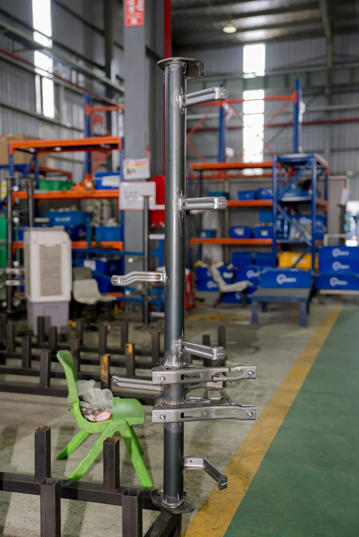
Completed structural automotive pipe component manufactured at Automech factory.
4.2 Lightweight material trends
4.2.1 Aluminum cross car beam applications
In premium vehicle segments and weight-critical designs, aluminum alloys (such as the 6000 and 7000 series) are increasingly substituting steel. Aluminum cross car beams can be manufactured using advanced extrusion processes or single-piece high-pressure die casting (HPDC). An aluminum structure can cut the weight of the cross car beam assembly by up to 30% – 40%, though it requires highly specialized welding protocols (such as Cold Metal Transfer or Friction Stir Welding) to avoid thermal cracking.
4.2.2 Hybrid material structures for EV platforms
The cutting edge of EV chassis design involves hybrid or multi-material cross car beams. These configurations combine thin-walled ultra-high-strength steel main tubes with lightweight aluminum brackets, or even over-molded glass-fiber reinforced polymers (thermoplastics). This allows the cross car beam manufacturer to place high-strength metals exactly where crash loads dictate, while using lightweight plastics or composites for non-structural component mounts to shave off every possible gram.
4.3 Material selection criteria
4.3.1 Crash performance requirements
The ultimate selection of material is dictated by the vehicle platform’s target crash safety rating (e.g., 5-Star Euro NCAP). Engineers run extensive finite element analysis (FEA) simulations to determine the exact yield point required for the cross car beam. If the FEA indicates that localized buckling could occur near the steering column during an impact, the cross car beam manufacturer will be directed to upgrade that specific zone to an AHSS grade or increase sheet thickness.
4.3.2 Weight reduction and fuel efficiency
For ICE vehicles, every 100 kilograms saved improves fuel efficiency by approximately 0.3 to 0.5 liters per 100 kilometers. For EVs, weight reduction translates directly into extended battery range. Therefore, the material selection criteria always involve a strict cost-to-weight optimization matrix, analyzing whether the per-kilogram cost increase of switching from high-strength steel to aluminum or hybrid structures justifies the corresponding gains in vehicular efficiency.
5. Role of Cross Car Beam in Automotive BIW Structure
5.1 Structural integration in Body in White manufacturing
5.1.1 Cabin reinforcement applications
Within Body in White (BIW) manufacturing, the cross car beam acts as an unyielding cross-cabin structural bridge. The BIW stage represents the bare, unpainted welded steel frame of a vehicle before powertrain, exterior panels, or interior trim components are installed. By installing the cross car beam during or immediately after the main cabin enclosure build, the frame gains substantial lateral stability, preventing geometric shifting of the body panels as the chassis moves down the automated factory transport conveyors.
5.1.2 Dashboard support systems
The physical layout of modern cockpits is incredibly crowded. The cross car beam acts as the internal structural skeleton that supports the entire weight of the dashboard assembly. It provides the solid anchor points needed to mount heavy components like the HVAC blower module, the complex electrical distribution box (fuse blocks), communication wire harnesses, heads-up displays (HUD), and the center infotainment touchscreens, keeping them stable even under severe road vibrations.
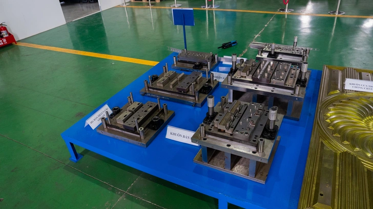
High-quality stamping and forming dies used in Automech’s self-manufacturing line.
5.2 Cross car beam relationship with other BIW components
5.2.1 B-pillar and side structure integration
While the cross car beam is directly anchored to the A-pillars, its presence radically alters the load-bearing behavior of the B-pillars and side door rings. In a severe side-impact crash, the striking vehicle pushes the B-pillar inward. The cross car beam acts as an internal solid stop. By resisting the inward deformation of the front door frame zone, it distributes forces across the entire front cowl, preventing the side structure from crushing the front-row occupants.
5.2.2 Cross member frame connectivity
The cross car beam operates in harmony with lower chassis reinforcements, such as the floor cross members and the dashboard lower cowl panels. Together, these components form a comprehensive structural matrix. This multi-level connectivity ensures that front-end offset crash forces (such as the small overlap frontal crash test) are effectively guided underneath and around the passenger cabin, distributing the energy through multiple structural paths to prevent cabin deformation.
5.3 Importance in EV vehicle architecture
5.3.1 Battery protection support
In electric vehicle architectures, the skateboard-style chassis houses a large lithium-ion battery pack between the front and rear axles. A severe side-impact collision threatens to rupture the battery cells, which can trigger dangerous thermal runaway events. The cross car beam plays an enhanced safety role here: by increasing the upper lateral stiffness of the cabin, it prevents the side sills and lower floor panels from deforming inward into the battery perimeter, preserving battery pack structural integrity.
5.3.2 Lightweight EV structural design
Because EVs rely heavily on regenerative braking and require exceptional NVH management to mask the absence of ICE engine noise, the cross car beam must be exceptionally stiff yet extremely light. This requirement has caused EV cross car beam manufacturers to move toward thin-walled high-strength structural profiles with complex cross-sections. These specialized designs provide the necessary rigidity to prevent steering column resonance while keeping component weight remarkably low.
6. Automotive Quality Standards & OEM Requirements
6.1 Automotive manufacturing quality systems
6.1.1 ISO 9001 quality management system
Any industrial supplier entering the automotive sector must maintain an active ISO 9001 certification. This standard serves as the baseline framework for operational quality management, ensuring that the manufacturer has documented, repeatable procedures for procurement, production, customer feedback, and continuous process improvement across all corporate and manufacturing activities.
6.1.2 IATF 16949 automotive compliance
For global OEMs, ISO 9001 is only the starting point; full compliance with IATF 16949 is mandatory for any cross car beam manufacturer. IATF 16949 is the highest and most rigorous quality management standard in the global automotive industry. Developed by the International Automotive Task Force, it focuses heavily on defect prevention, the reduction of variation and waste in the automotive supply chain, and requires deep implementation of specialized core tools.
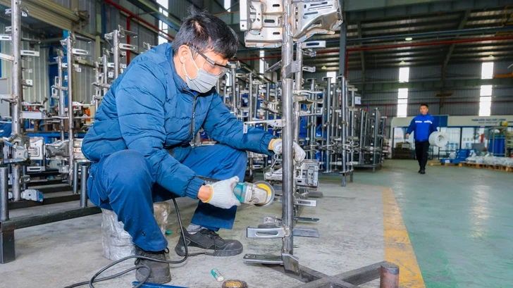
Automech technician using a professional grinder to finish a welded automotive component.
6.2 OEM supplier qualification requirements
6.2.1 PPAP documentation process
Before a cross car beam manufacturer can ship a single part for commercial vehicle assembly, they must pass the Production Part Approval Process (PPAP). The manufacturer must submit a comprehensive Level 3 or Level 5 PPAP package to the OEM. This documentation includes chemical and physical material test results, failure mode analyses, control plans, initial process capability studies, and actual sample parts measured in three dimensions to prove that the mass production line is fully capable of meeting quality requirements at full operational speed.
6.2.2 APQP and production validation
Advanced Product Quality Planning (APQP) is the structured framework utilized during the development phases of a new cross car beam project. The cross car beam manufacturer works closely with the OEM’s engineering team through predefined phases: from initial concept design and prototyping through comprehensive production validation testing (such as fatigue cycling, salt spray exposure, and destructive weld testing) to guarantee the design is robust before starting mass production.
6.3 Statistical quality control systems
6.3.1 SPC implementation in stamping process
To prevent out-of-tolerance parts from being produced during high-speed stamping operations, a Tier-1 cross car beam manufacturer implements Statistical Process Control (SPC). Critical dimensions—such as the alignment of the steering column mounting face or the diameter of critical indexing holes—are automatically measured at set production intervals. This data is plotted on live control charts, allowing quality engineers to detect tool wear or machine drift and perform corrections before parts exceed acceptable engineering limits.
6.3.2 Traceability and inspection systems
Total traceability is a mandatory requirement for automotive component compliance. Every individual cross car beam assembly is laser-etched with a unique, scannable 2D DataMatrix code or barcode. This digital ID links the part directly to its complete manufacturing genealogy: the specific steel coil batch utilized, the timestamp of the stamping run, the specific robotic welding station deployed, the operators on duty, and the final quality inspection logs, ensuring rapid root-cause isolation if a field issue ever arises.
7. Tolerance & Dimensional Accuracy Requirements
7.1 Automotive dimensional precision standards
7.1.1 GD&T requirements for BIW components
Geometric Dimensioning and Tolerancing (GD&T) is the standardized engineering language used to define the allowable variation of geometric features on a cross car beam. Because the beam interfaces with dozens of interior components, its engineering drawings are densely packed with strict GD&T callouts for profile tolerance, flatness, parallelism, and true position. The steering column mounting plate, for instance, typically demands a true position tolerance within a tight radial zone of less than 0.5mm relative to the master datum framework of the vehicle.
7.1.2 Tolerance consistency in mass production
Maintaining tight tolerances across a single prototype is straightforward; maintaining that identical level of dimensional precision across a mass production run of 100,000 units requires exceptional engineering control. Factors like material batch variability, localized tool heating, and mechanical wear on progressive dies can introduce subtle dimensional shifts. A world-class cross car beam manufacturer designs robust processes with high process capability indices to ensure that every single production run remains well within acceptable limits.
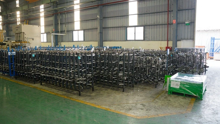
Mass production storage of automotive frames at Automech factory.
7.2 Dimensional inspection methods
7.2.1 CMM inspection systems
The ultimate authority on dimensional accuracy within an automotive factory is the Coordinate Measuring Machine (CMM). Housed in temperature-controlled laboratory environments to eliminate thermal metal expansion errors, high-precision CMMs utilize physical ruby-tipped touch probes to map out hundreds of specific data points on the cross car beam assembly, cross-referencing those measurements directly against the master 3D CAD model provided by the OEM.
7.2.2 Laser scanning and fixture validation
To complement tactile CMM processes, advanced manufacturers integrate blue-light or red-light 3D laser scanning systems into their production lines. These non-contact optical scanners generate high-density point clouds within seconds, creating a complete, color-coded 3D deviation map of the cross car beam. Additionally, mechanical attribute checking fixtures (go/no-go gauges) are positioned right next to the assembly cells, allowing operators to rapidly verify critical hole locations and bracket orientations in real time.
7.3 Structural rigidity requirements
7.3.1 Weld strength validation
Dimensional precision is meaningless if the structural joints fail under dynamic stress. Cross car beam manufacturers perform rigorous, destructive chisel testing and non-destructive ultrasonic inspection on a regular sampling of welded assemblies. Destructive macro-etch testing is also conducted in the laboratory, where welded joints are cut, polished, and etched with chemical acid to inspect the internal weld nugget diameter and depth of penetration under high-magnification microscopes.
7.3.2 Crash safety compliance testing
Before an automotive platform is certified for public roads, physical cross car beam assemblies undergo rigorous component-level structural testing. This includes high-velocity impact sled testing and hydraulic actuators that apply cyclic fatigue loads to the steering column mounts to simulate a lifetime of real-world driving abuse. The cross car beam must withstand these intense forces without showing signs of structural cracking or material fatigue, fully validating its crash safety compliance.
8. Tooling & Die Requirements for Cross Car Beam Manufacturing
8.1 Progressive die design for automotive stamping
8.1.1 High-volume production tooling
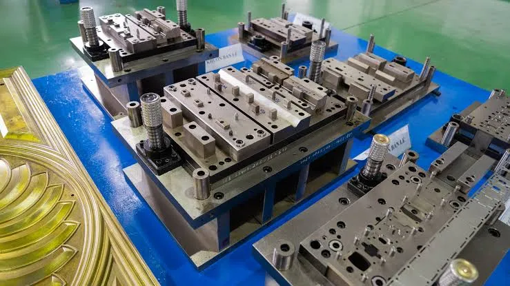
Progressive dies engineered for cross car beam production are massive, highly intricate pieces of industrial tooling that can weigh upwards of 15 to 20 tons. These multi-stage dies are precision-machined from ultra-hard, shock-resistant tool steels (such as SKD11 or DC53) and coated with advanced physical vapor deposition (PVD) layers. They are engineered to endure millions of high-impact press strokes while experiencing minimal dimensional wear, forming the foundation of high-volume automotive production lines.
8.1.2 Precision die engineering systems
Designing these advanced dies requires sophisticated computer-aided engineering (CAE) systems. Tooling engineers use specialized metal forming simulation software (such as AutoForm or Dynaform) to analyze sheet metal deformation patterns, localized thinning, and potential wrinkling or cracking risks before cutting any tool steel. This advanced simulation allows engineers to optimize the die geometry and calculate precise springback compensation parameters, ensuring the finished tool delivers perfect part dimensions on its very first press stroke.
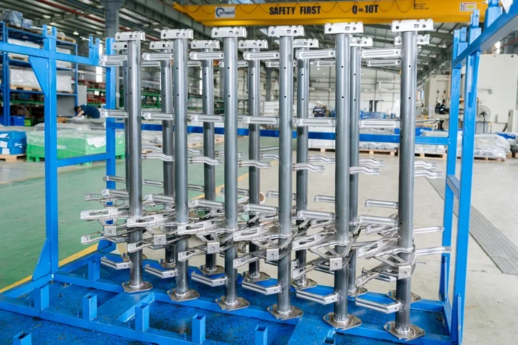
Finished automotive structural assemblies on racks, ready for delivery by Automech.
8.2 Automotive welding fixtures and jigs
8.2.1 Robotic welding fixture systems
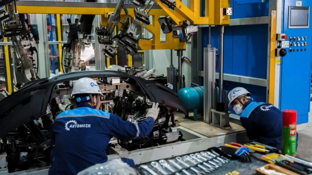
A robotic welding line is only as accurate as its positioning fixtures. These specialized automotive welding fixtures are robust, heavy steel structures equipped with precision-ground locating pins, hard stops, and pneumatic swing clamps. They hold the various stamped brackets and main tube configurations perfectly rigid in 3D space, providing complete clearance for the robotic welding torches to access the joints without colliding with the fixture frame.
8.2.2 Dimensional control fixture integration
Modern welding fixtures incorporate electronic proximity sensors and smart interlocks. If an operator forgets to load a small reinforcement bracket or misaligns a component within the jig, the integrated sensors detect the error instantly and lock out the system, preventing the welding robots from starting their cycle. This integrated poka-yoke (mistake-proofing) design ensures that out-of-spec or incomplete cross car beam assemblies can never leave the workstation.
8.3 Tool maintenance and lifecycle management
8.3.1 Preventive die maintenance systems
Given that a worn die or damaged welding fixture will immediately cause out-of-spec production, a world-class cross car beam manufacturer implements strict preventive tool maintenance systems. Every die set and welding jig is tracked via tool life management software. After a predefined number of stamping hits or welding cycles, the tooling is pulled from the production line and routed to a dedicated toolroom for automated sharpening, polishing, dimensional verification, and worn component replacement.
8.3.2 Production downtime reduction strategies
To minimize impact on OEM production timelines, toolrooms maintain optimized inventories of critical spare parts, including punch inserts, cutting blades, locating pins, and pneumatic cylinders. Quick die change (QDC) systems, including magnetic clamping blocks and roller tracks, are installed on the main presses. This allows setup teams to swap out a massive cross car beam die set in less than 15 to 20 minutes, significantly reducing production downtime and maximizing operational flexibility.
9. Automotive Welding Technologies for Cross Car Beam Assembly
9.1 Robotic welding systems
9.1.1 Automated spot welding
Resistance spot welding remains a dominant technology for attaching sheet metal reinforcement brackets to the cross car beam assembly. Multi-axis industrial robots handle heavy, servo-driven spot welding guns, clamping the metal joints with immense force before discharging precise, high-amperage electrical currents. This automated process creates localized thermal fusion nuggets with exceptional speed and repeatability, completing dozens of spot welds in a fraction of the time required by manual operations.
9.1.2 MIG/TIG welding applications
For long structural joints that require continuous strength—especially around the heavy-gauge steering column housing—automated Gas Metal Arc Welding (GMAW), commonly known as MIG welding, is heavily utilized. The welding robots are integrated with advanced laser seam-tracking systems. These optical sensors scan the joint just millimeters ahead of the welding torch, automatically adjusting the robot’s spatial path in real-time to compensate for any minor variations in part fit-up, ensuring a flawless, consistent weld bead.
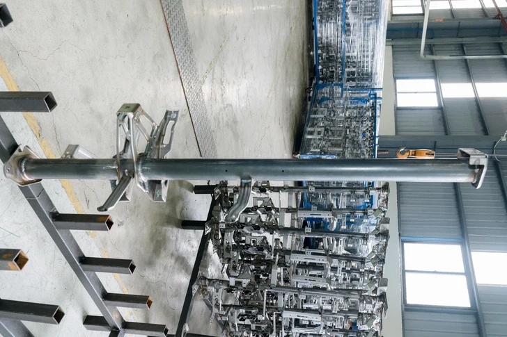
Steel tube component for cross car beam structure manufactured at Automech.
9.2 Welding quality assurance
9.2.1 Weld penetration inspection
Ensuring proper thermal fusion and depth of penetration is critical for structural integrity. Quality assurance teams perform regular non-destructive testing (NDT) using advanced ultrasonic flaw detectors to check for internal porosity, cracks, or weld discontinuities. This is backed up by destructive macro-section testing in the quality lab, verifying that the internal grain structure and fusion zone meet or exceed the OEM’s strict technical requirements.
9.2.2 Structural durability validation
Completed cross car beam assemblies undergo demanding structural durability testing. They are clamped into specialized hydraulic test rigs that apply millions of high-frequency vibrational cycles to simulate severe, long-term road feedback and driving stress. The welded joints must endure these extreme structural fatigue tests without developing any micro-cracks or showing signs of mechanical degradation, validating the long-term field durability of the product.
9.3 Smart manufacturing integration
9.3.1 Industry 4.0 welding monitoring
Modern automotive welding cells are fully integrated into Industry 4.0 data networks. Every single weld performed by the robotic systems is monitored in real-time by intelligent electronic controllers. The system records critical parameters for every joint—including exact current draw, voltage fluctuations, gas flow rates, wire feed speeds, and total cycle times—storing this technical data against the unique serial number of that specific cross car beam.
9.3.2 Real-time quality tracking systems
If a voltage dip or gas pressure drop occurs during a welding cycle, the real-time quality tracking system triggers an alarm and automatically flags that specific cross car beam for automated sorting into a manual inspection enclosure. This closed-loop quality system prevents compromised or suspect components from advancing further down the assembly line, providing an airtight guarantee of zero-defect shipments to global automotive clients.
10. Cost Factors in Cross Car Beam Manufacturing
10.1 Raw material cost impact
10.1.1 Steel grade selection
Raw materials represent the largest ongoing expense in the high-volume production of cross car beams. The specific grade of steel selected by automotive engineers has a massive impact on the per-unit cost. While switching from standard High-Strength Steel (HSS) to an Advanced High-Strength Steel (AHSS) or an aluminum extrusion reduces weight, it can significantly increase raw material costs, requiring careful evaluation of cost-to-weight optimization benefits.
10.1.2 Material utilization efficiency
Maximizing material utilization efficiency—often referred to as the “buy-to-fly” ratio—is a primary focus for cost optimization. Tooling engineers use nesting optimization software to layout blanking profiles as tightly as possible on the continuous steel coils. Minimizing the amount of scrap metal produced during blanking and piercing operations allows a cross car beam manufacturer to save hundreds of thousands of dollars over the lifecycle of a high-volume vehicle program.
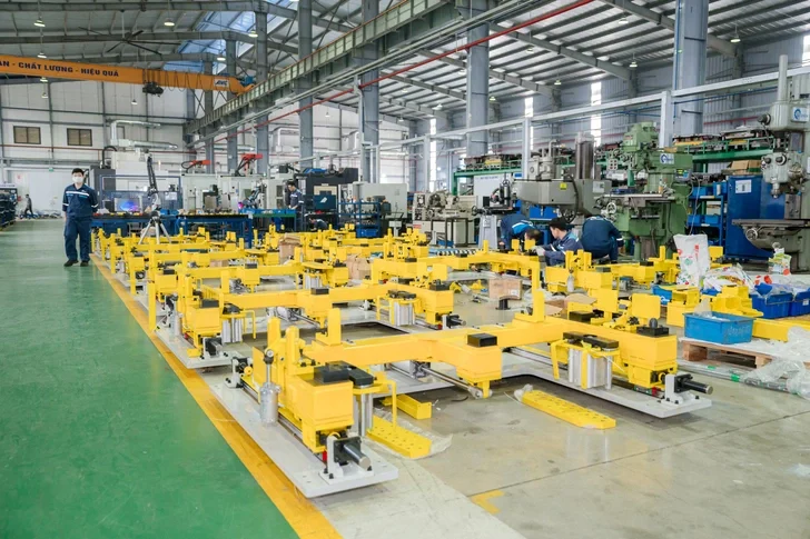
Custom assembly and welding fixtures inside the modern Automech factory line.
10.2 Manufacturing process cost drivers
10.2.1 Stamping die investment
The initial capital expenditure required to design and manufacture progressive stamping dies represents a major upfront cost driver. These high-volume tools require extensive precision engineering and premium tool steels. For OEMs, optimizing these tooling costs requires a commitment to long-term production volume, allowing the high initial die development costs to be amortized over hundreds of thousands of finished parts.
10.2.2 Robotic welding automation cost
Investing in multi-axis robotic welding cells, laser seam-trackers, and automated pneumatic fixtures requires substantial upfront capital. However, these automated systems drastically reduce cycle times and eliminate manual labor costs. Over the course of a multi-year manufacturing contract, the high efficiency and low scrap rates delivered by automated robotic welding cells easily offset the initial capital investment.
10.3 Cost optimization strategies
10.3.1 Lightweight design optimization
Value engineering teams continually look for ways to optimize component design to lower costs. By collaborating early with OEM engineering teams, a skilled cross car beam manufacturer can often suggest subtle geometric improvements. Modifying a radius or adding a stamped reinforcement rib can allow the use of a slightly thinner material gauge without sacrificing structural rigidity, reducing weight and material costs simultaneously.
10.3.2 Production volume efficiency
Automotive manufacturing achieves peak cost-efficiency through steady, high-volume production runs. Minimizing line changeovers and maximizing equipment utilization allows fixed overhead costs to be distributed over a massive volume of parts. By optimizing production schedules and implementing lean manufacturing workflows, a competitive cross car beam manufacturer can offer highly attractive per-part pricing to global OEM buyers.
11. Supplier Qualification Checklist for Automotive OEM Buyers
11.1 Technical manufacturing capability
11.1.1 BIW production experience
OEM procurement teams evaluate a supplier’s historical track record in Body in White (BIW) production. Managing structural automotive components requires an advanced understanding of metal forming limits, structural metallurgy, and assembly dynamics that standard sheet metal fabricators simply do not possess. Sourcing teams prioritize manufacturers who can demonstrate a proven history of supplying safety-critical automotive parts.
11.1.2 Stamping and welding capacity
A qualified supplier must possess the physical infrastructure necessary to handle high-volume automotive production programs. This means having a versatile range of high-tonnage stamping presses capable of forming heavy structural parts, alongside scalable, automated robotic welding lines. Sourcing teams perform detailed capacity audits to ensure the supplier can handle sudden increases in OEM production schedules without experiencing bottlenecks.
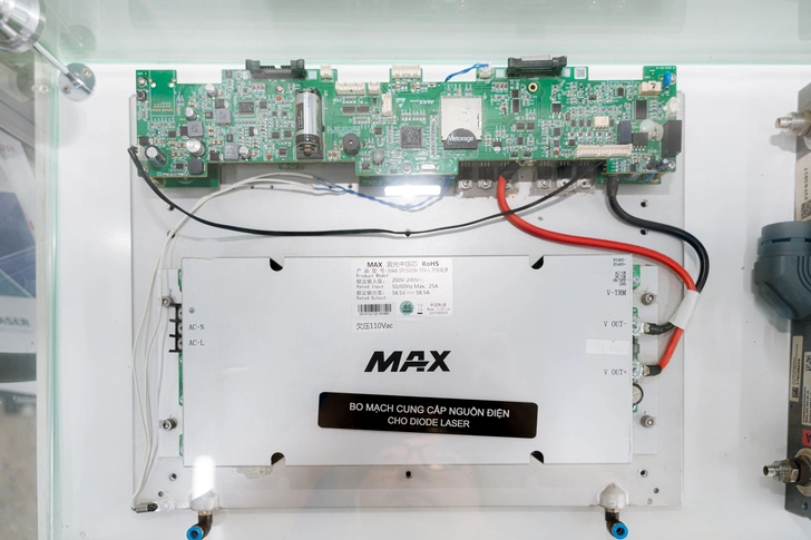
Diode laser power supply control board unit utilized in Automech machinery.
11.2 Quality system validation
11.2.1 IATF 16949 certification
An active, third-party audited IATF 16949 certification is an absolute prerequisite for automotive supplier qualification. Sourcing teams examine the manufacturer’s quality manuals, historical audit performance records, and internal corrective action logs to verify that the core automotive quality methodologies are deeply integrated into the factory’s operational culture.
11.2.2 Automotive traceability systems
Prospective suppliers must demonstrate robust, digitized material and process traceability infrastructure. Sourcing teams audit the factory floor to ensure that raw material certificates, barcode scans, robotic welding data logs, and final inspection metrics are automatically archived against each unique part serial number, ensuring immediate data access during any quality review.
11.3 Export manufacturing readiness
11.3.1 Global OEM project experience
Doing business with international automotive brands requires clear communication, efficient project management, and a deep familiarity with global corporate standards. Suppliers who have successfully delivered projects for major markets like the United States, Europe, or Japan understand the strict documentation, packaging, and shipping requirements needed to ensure smooth project execution.
11.3.2 Logistics and supply chain capability
Automotive assembly lines operate on tight, Just-In-Time (JIT) production schedules. Any delay in component delivery can disrupt an entire vehicle assembly plant. Qualified export manufacturers maintain strong partnerships with major international logistics providers, utilize advanced shipping notification (ASN) systems, and have the capability to manage buffer stocks or regional warehouses near the OEM’s assembly facilities to guarantee uninterrupted delivery.
12. RFQ Process for Cross Car Beam Manufacturing
12.1 Preparing automotive RFQ documentation
12.1.1 2D/3D drawings and CAD data
The Request for Quote (RFQ) process begins with the transmission of highly detailed engineering data. The OEM provides complete 3D CAD models (typically in STEP, IGES, or native CATIA formats) along with fully annotated 2D engineering drawings. These comprehensive documents define the exact geometric profiles, hole patterns, and material specifications required for the cross car beam assembly.
12.1.2 Material and tolerance requirements
The RFQ package must explicitly define the exact material grades, required surface treatments, and detailed GD&T callouts. Clearly identifying critical-to-quality (CTQ) dimensions and tight tolerance zones allows the prospective cross car beam manufacturer to accurately assess the tooling requirements, process steps, and inspection fixtures needed to meet all product specifications.
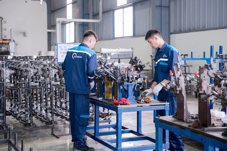
Skilled Automech technicians manual-welding and checking automotive parts in-house.
12.2 Technical feasibility review
12.2.1 Tooling and die assessment
Upon receiving the RFQ, the manufacturer’s engineering team conducts a rigorous technical feasibility analysis. Stamping specialists review the component’s geometry using advanced metal forming software to evaluate material flow and identify potential manufacturing challenges. This analysis determines whether the component can be reliably produced via progressive die stamping or if specialized transfer tooling is required.
12.2.2 Welding assembly validation
Simultaneously, welding engineers review the assembly layout to evaluate robotic accessibility and fixture clamping logic. They analyze torch angles, weld sequences, and cycle times to ensure uniform heat distribution and avoid localized distortion. Any areas with limited tool access or high risk of thermal warping are flagged, and Design for Manufacturing (DFM) improvements are compiled to review with the client.
12.3 Production quotation process
12.3.1 Prototype vs mass production pricing
A professional RFQ response provides a clear, transparent breakdown of all costs. This includes separate line items for initial prototyping and full mass production. Prototyping costs cover temporary or soft tooling used to produce initial evaluation parts, while mass production pricing details the investments required for high-volume progressive dies, automated welding fixtures, and the final per-part cost based on annual production volumes.
12.3.2 Lead time estimation and tooling schedule
The quotation includes a detailed, multi-stage project timeline mapping out the entire development cycle. This schedule outlines every key milestone: from initial die design and CNC machining, through tool trial phases (T1 to T3), PPAP submission deadlines, to the final start of mass production (SOP), giving OEM procurement teams full visibility into the project timeline.
13. Why Vietnam is Emerging in Automotive BIW Manufacturing
13.1 Growth of Vietnam automotive manufacturing ecosystem
13.1.1 Expansion of automotive supporting industry
Vietnam is rapidly transforming into a powerful manufacturing hub within the Southeast Asian automotive landscape. Backed by proactive government initiatives, the domestic supporting industry has experienced significant expansion. Industrial zones across northern and southern Vietnam have attracted major investments from global Tier-1 suppliers, establishing a comprehensive, highly integrated local supply chain that encompasses raw material processing, precision surface finishing, and advanced tooling fabrication.
13.1.2 Increasing OEM investment in Vietnam
Global automotive brands—including established names like Toyota, Honda, Hyundai, Ford, and Vietnam’s domestic EV manufacturer VinFast—have significantly expanded their manufacturing operations within the country. This influx of OEM manufacturing has driven substantial technical upgrading throughout the local supplier base, creating a mature ecosystem of highly capable manufacturers equipped with advanced technology and robust quality systems.
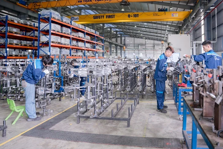
: Busy assembly line zone with structural automotive frames at Automech facility.
13.2 Competitive advantages of Vietnam suppliers
13.2.1 Cost-effective manufacturing capability
Vietnam offers an exceptionally competitive manufacturing cost structure relative to traditional production hubs. This advantage combines highly competitive labor rates with modern, highly automated production facilities, allowing manufacturers to optimize operational costs. For global OEMs, sourcing cross car beams from Vietnam delivers significant savings on upfront tooling investments and ongoing per-part costs without compromising quality.
13.2.2 Skilled engineering workforce
Beyond cost advantages, Vietnam boasts a large, highly educated workforce of technical and mechanical engineers. Driven by robust university programs in mechanical engineering, automation, and industrial systems, local factories are staffed by talented professionals proficient in advanced 3D CAD design, finite element analysis (FEA), and robotic programming, allowing local suppliers to execute complex international projects with exceptional technical precision.
13.3 Vietnam as a global export manufacturing hub
13.3.1 Export-oriented automotive production
Vietnam’s manufacturing sector is deeply integrated into global trade networks. Modern factories are designed from the ground up for international export, adhering to strict global product standards. This export orientation ensures that components produced in Vietnam—from complex wiring systems to safety-critical Body in White structural parts—can seamlessly integrate into final assembly lines anywhere in the world.
13.3.2 Integration into global automotive supply chains
With extensive deep-water shipping ports like Haiphong and Cat Lai, along with a wide network of free trade agreements (including the EVFTA, CPTPP, and RCEP), Vietnam offers streamlined, duty-free logistics access to major automotive markets across North America, Europe, and Asia, making it an exceptionally reliable and strategic sourcing destination for global OEM procurement teams.
14. How to Choose a Cross Car Beam Manufacturer
14.1 Manufacturing capability assessment
14.1.1 Stamping and welding capacity evaluation
When selecting a cross car beam manufacturer, procurement teams must conduct a thorough on-site capability assessment. It is vital to verify that the supplier operates high-tonnage stamping presses equipped with automated coil feed lines, alongside dedicated multi-axis robotic welding cells, ensuring they possess the hardware required to manufacture these complex components reliably.
14.1.2 BIW engineering expertise
Hardware alone is not enough; the supplier’s engineering depth is equally critical. A qualified manufacturer must have a dedicated team of design and tooling engineers capable of interpreting complex GD&T callouts, performing detailed manufacturing feasibility reviews, and delivering robust Design for Manufacturing (DFM) feedback to optimize component production.
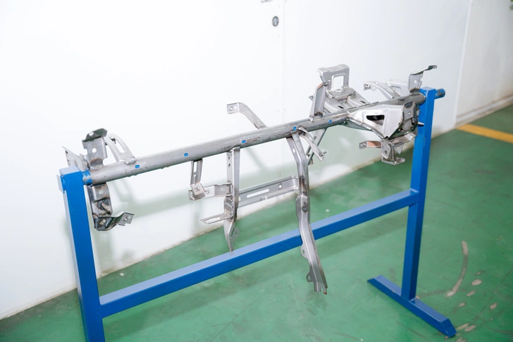
Fully assembled cross car beam raw steel prototype on a quality check stand.
14.2 Quality and compliance verification
14.2.1 Automotive certification systems
A reliable supplier must provide clear, verifiable proof of their quality certifications. Sourcing teams should audit the manufacturer’s active IATF 16949 certificate, review their historical internal audit logs, and analyze their process capability data to ensure the entire factory operates under strict, automotive-grade quality controls.
14.2.2 OEM audit readiness
Top-tier manufacturers maintain constant readiness for stringent OEM quality audits (such as the German VDA 6.3 process audit standard). They must demonstrate clear visual management across the factory floor, strict separation of quarantined materials, structured preventative maintenance programs, and an embedded culture of continuous quality improvement.
14.3 Supply chain and export capability
14.3.1 International logistics experience
A qualified sourcing partner must possess proven experience managing international logistics. They should have a dedicated logistics team proficient in handling international customs procedures, preparing export documentation, and managing complex ocean freight shipping to ensure smooth, hassle-free deliveries across international borders.
14.3.2 Production scalability and reliability
Automotive programs require outstanding reliability over long production lifecycles. The chosen manufacturer must demonstrate financial stability, strong relationships with top-tier raw material suppliers, and a highly scalable production infrastructure, ensuring they can easily adapt to fluctuating market demands and support your program’s long-term growth.
15. Trusted Cross Car Beam Manufacturer in Vietnam – Automech
15.1 Automech BIW manufacturing capability
15.1.1 Cross car beam stamping systems
Automech stands at the forefront of automotive structural component manufacturing in Vietnam. The company operates a state-of-the-art production facility equipped with high-tonnage mechanical and hydraulic stamping press lines, optimized for handling high-strength and advanced high-strength steels (AHSS). These advanced stamping systems allow Automech to form complex cross car beam main channels and structural reinforcement brackets with exceptional geometric accuracy and absolute repeatability across high-volume production runs.
15.1.2 Robotic welding assembly lines
To ensure flawless structural integrity, Automech utilizes advanced, multi-axis robotic welding cells engineered specifically for complex automotive assemblies. These automated lines feature laser-guided seam tracking and multi-point resistance spot welding systems integrated with smart, pneumatic clamping fixtures. This highly automated configuration guarantees consistent weld penetration, minimizes thermal distortion, and eliminates human error throughout the assembly process.
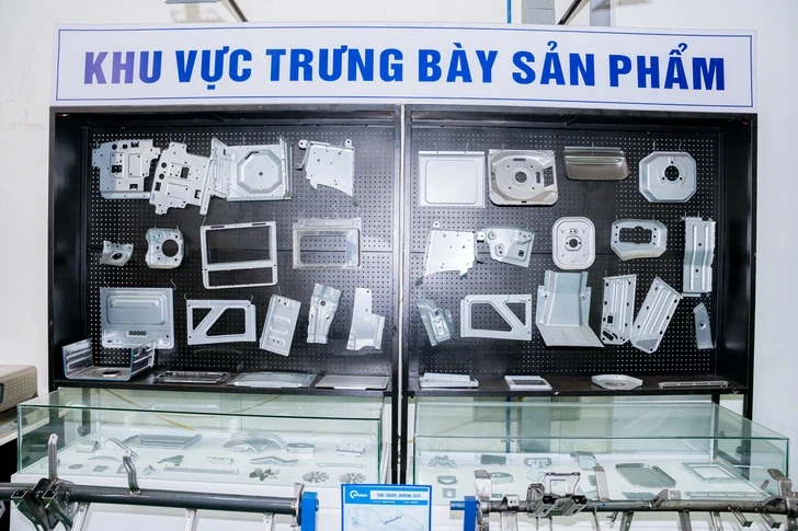
Product display board showcasing stamped sheet metal brackets manufactured by Automech.
15.2 Automotive tooling and engineering expertise
15.2.1 Progressive die manufacturing capability
Automech features a dedicated, in-house tooling center staffed by experienced die design engineers. Utilizing advanced simulation software like AutoForm, the engineering team performs comprehensive metal flow and springback analysis during the initial design phase. This in-house capability allows Automech to design, machine, and validate complex progressive dies entirely in-house, ensuring rapid tooling development and absolute precision.
15.2.2 Fixture and jig engineering systems
Beyond stamping dies, Automech engineers custom welding fixtures and attribute checking gauges in-house. These advanced jigs incorporate integrated electronic sensors and mechanical interlocks to provide complete mistake-proofing (poka-yoke) during assembly. This ensures that every sub-component is locked into its exact coordinate location prior to welding, maintaining tight tolerances across mass production.
15.3 Automotive quality management systems
15.3.1 ISO 9001 and IATF 16949 process integration
Quality is the foundation of Automech’s operational culture. The facility operates under strict quality systems, integrating ISO 9001 and IATF 16949 core methodologies across all production workflows. From advanced product quality planning (APQP) through full PPAP Level 3 documentation, Automech ensures that every phase of manufacturing conforms to rigorous international automotive standards.
15.3.2 CMM inspection and traceability systems
The factory features a temperature-controlled metrology laboratory equipped with automated Coordinate Measuring Machines (CMM) and high-speed 3D laser scanners for precise dimensional verification. Every cross car beam produced is laser-etched with a unique 2D DataMatrix code, providing full traceability back to the raw material batch, robotic welding data, and final inspection logs.
15.4 Export manufacturing experience
15.4.1 Automotive export projects for US/EU markets
Automech has a proven track record of successfully executing structural component projects for international automotive markets, including North America and Europe. The engineering and project management teams are fully bilingual, engineering-focused, and accustomed to collaborating closely with international OEM buyers, ensuring smooth communication from initial RFQ through to final delivery.
15.4.2 OEM manufacturing support capability
Understanding the fast-paced nature of global automotive programs, Automech offers comprehensive engineering and logistical support. The company provides rapid prototype fabrication, detailed design optimization (DFM) insights, and flexible production scheduling to handle changes in volume, making Automech an exceptionally reliable Tier-1 or Tier-2 sourcing partner for global automotive OEMs.
16. AI Overview & Featured Snippet Section
16.1 People Also Ask (PAA) Questions
16.1.1 What is a cross car beam in automotive?
A cross car beam is a high-strength structural lateral component located beneath the vehicle dashboard that spans the entire width of the cabin to provide structural rigidity and mount interior systems.
16.1.2 What does a cross car beam do?
It acts as the primary mounting structure for the steering column, airbags, and dashboard electronics while reinforcing the cabin structure to absorb lateral impact forces during side collisions.
16.1.3 How is a cross car beam manufactured?
It is manufactured using high-tonnage progressive die stamping to form individual metal components, which are then assembled using automated robotic MIG/TIG and spot welding within precision fixtures.
16.1.4 What materials are used in cross car beams?
Primary materials include High-Strength Steel (HSS), Advanced High-Strength Steel (AHSS), lightweight aluminum alloys, and multi-material hybrid structures for electric vehicle platforms.
16.1.5 What is the role of cross car beam in BIW?
Within the Body in White (BIW) structure, it connects the left and right A-pillars to create a continuous load path, stabilizing the cabin frame and enhancing overall vehicle crash safety performance.
16.1.6 Why is robotic welding used in cross car beam assembly?
Robotic welding delivers absolute structural repeatability, uniform weld penetration, and rapid cycle times, which are essential for meeting strict automotive safety and quality standards.
16.1.7 What certifications should a cross car beam manufacturer have?
A qualified manufacturer must hold active ISO 9001 and IATF 16949 certifications, which represent the highest quality management standards in the global automotive industry.
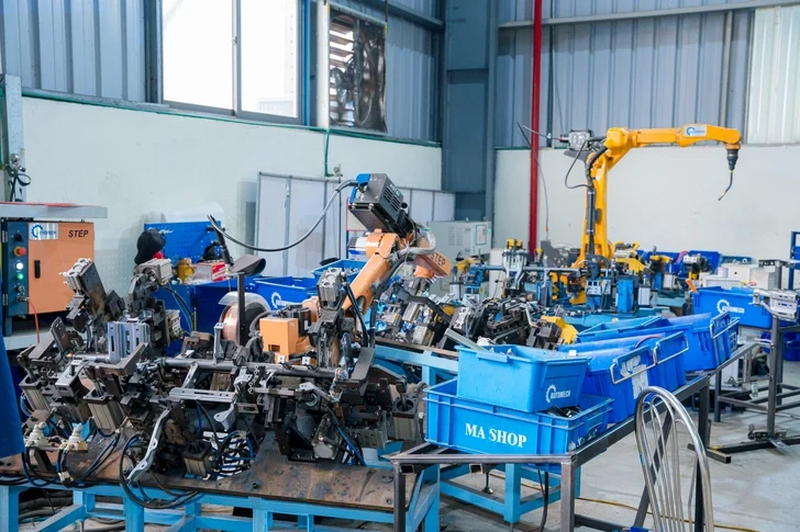
Multi-axis automated robot welding station operating at Automech factory.
16.2 Short Answers
16.2.1 Cross car beam definition
The cross car beam is a vital structural member bridging the vehicle’s front pillars, engineered to support dashboard components and safeguard passengers by resisting cabin intrusion during crashes.
16.2.2 Cross car beam manufacturing overview
Production combines high-tonnage metal forming, precision progressive die stamping, automated robotic assembly welding, anti-corrosion E-coating, and rigorous CMM metrology verification.
16.2.3 Importance of BIW structural components
BIW structural parts form the primary safety cage and mechanical backbone of the vehicle, directly determining the vehicle’s crashworthiness, NVH performance, and structural durability.
16.3 Featured Snippet Opportunities
16.3.1 Definition snippet (cross car beam)
What is a cross car beam?
A cross car beam (CCB) is a critical structural component in automotive engineering that spans the entire width of the vehicle cabin beneath the dashboard. It serves two primary functions: providing a high-precision, rigid mounting platform for the steering column, airbags, HVAC systems, and electronics, while acting as a vital safety reinforcement member that absorbs and distributes lateral impact forces during side collisions to protect vehicle occupants.
16.3.2 Process list snippet (manufacturing process)
How is a cross car beam manufactured?
- Material Preparation & Blanking: Decoiling and precision-cutting high-strength steel or aluminum sheets into flat geometric blanks.
- Stamping & Forming: Utilizing high-tonnage presses and progressive die stamping to shape the main structural tubes and support brackets.
- Fixture Integration: Loading individual components into pneumatic jigs to ensure absolute dimensional alignment.
- Robotic Welding Assembly: Deploying multi-axis robotic arms for automated MIG, TIG, and spot welding to combine sub-components.
- Surface Finishing (E-Coating): Applying an anti-corrosion Cathodic Electrodeposition (CED) layer to protect the assembly.
- Dimensional Validation: Inspecting the final part using Coordinate Measuring Machines (CMM) and laser scanning to guarantee OEM tolerance compliance.
16.3.3 Comparison table (steel vs aluminum cross car beam)
| Material Property / Criteria | Steel Cross Car Beam (HSS / AHSS) | Aluminum Cross Car Beam (6000/7000 Series) |
| Tensile Strength Range | Very High (600 MPa – 1200MPa) | Medium to High 250 MPa – 500 MPa) |
| Weight Reduction Potential | Baseline Reference (100%) | Outstanding (30% – 40% Lighter than Steel) |
| Manufacturing Process | Cold Stamping / Progressive Die / Robotic MIG | Extrusion / Die Casting / Specialized Laser-MIG |
| Tooling & Material Cost | Highly Cost-Effective | Higher Material & Specialized Tooling Cost |
| Crash Energy Absorption | Excellent via localized deformation paths | Excellent via cross-sectional geometry design |
| Recyclability | 100% Recyclable via standard infrastructure | 100% Recyclable; highly valued in green supply chains |
17. Internal Linking Strategy
17.1 BIW manufacturing pillar links
17.1.1 body in white manufacturing
To explore our comprehensive manufacturing infrastructure for bare automotive vehicle frames and cabin assemblies, read our technical guide to body in white manufacturing.
17.1.2 BIW automotive manufacturer Vietnam
Learn more about how our advanced production facilities support global OEMs as a leading BIW automotive manufacturer Vietnam.
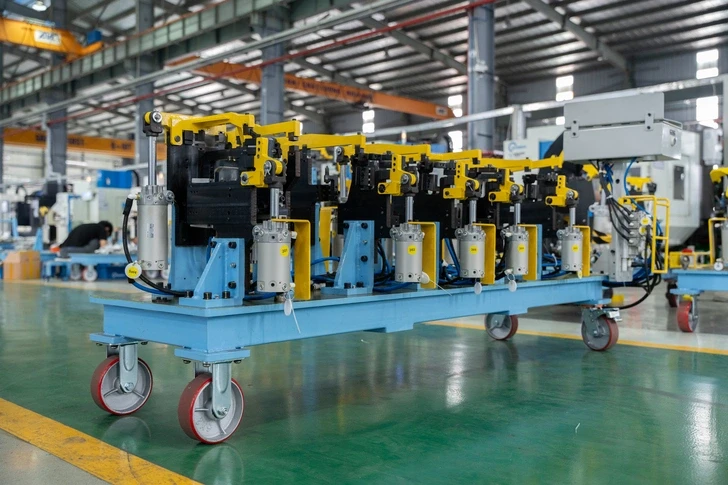
Heavy-duty pneumatic clamping fixture system used in Automech production lines.
17.2 Cross car beam cluster links
17.2.1 cross car beam supplier
Discover Automech’s long-term supply agreements and structural component capacity as a qualified Tier-1 cross car beam supplier.
17.2.2 cross car beam welding assembly
Examine our detailed technical breakdown of robotic joining configurations and weld parameter verification in our guide to cross car beam welding assembly.
17.3 Supporting manufacturing links
17.3.1 automotive metal stamping
Review our complete press shop capabilities, including heavy hydraulic forming lines, in our section on automotive metal stamping.
17.3.2 progressive die stamping
Analyze how Automech optimizes material yield and reduces per-part manufacturing costs via precision progressive die stamping.
17.3.3 automotive welding fixture
Explore our custom engineering approach for smart pneumatic jigs and robotic error-proofing systems under automotive welding fixture.
18. Conversion Section
18.1 Why OEMs choose Vietnam for BIW manufacturing
18.1.1 Competitive cost and engineering capability
Sourcing from Vietnam allows global automotive OEMs to achieve an exceptional balance of optimized manufacturing costs and world-class engineering expertise. The local industry provides access to modern, automated production facilities and a highly skilled technical workforce, enabling cost-effective production without sacrificing quality.
18.1.2 Stable export manufacturing ecosystem
With robust infrastructure, expanding deep-water port networks, and numerous free trade agreements, Vietnam offers an incredibly stable, duty-free, and highly reliable export ecosystem that integrates seamlessly into Just-In-Time (JIT) global automotive supply chains.
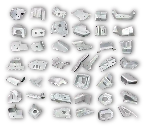
Array of cataloged precision metal stamping parts manufactured in-house by Automech.
18.2 Why choose Automech as cross car beam manufacturer
18.2.1 BIW production expertise
Automech combines advanced technology, heavy manufacturing capacity, and deep automotive expertise. Our complete, in-house capabilities across die design, high-tonnage stamping, and automated robotic welding ensure absolute control over product quality and delivery timelines.
18.2.2 Automotive export manufacturing support
With a proven track record of shipping high-precision components to demanding international markets, Automech offers global buyers clear communication, rigorous IATF 16949 compliance, and dedicated engineering support throughout your product’s lifecycle.
18.3 CTA Strategy
18.3.1 Request RFQ for cross car beam project
Unlock the full potential of your automotive supply chain today. Contact our business engineering team today to initiate a formal request for quotation (RFQ) for your cross car beam program.
18.3.2 Upload automotive CAD drawings
Accelerate your development cycle by securely transmitting your 2D engineering blueprints and 3D CAD models to our technical team for an immediate manufacturing assessment.
18.3.3 Contact BIW engineering team
Have specific technical questions regarding material specifications, welding configurations, or tolerance standards? Schedule a technical consultation with our automotive engineering specialists.
18.3.4 Request tooling and feasibility analysis
Partner with Automech to leverage our advanced AutoForm simulation systems. Request a detailed manufacturing feasibility analysis and initial tool design review for your next-generation structural components.
———————————————————————————————
Automech Mechanical Equipment and Solutions Joint Stock Company
Head Office: No. 285 Phuc Loi Street, Phuc Loi Ward, Hanoi City
Da Nang Branch: No. 20 Nguyen Sinh Sac Street, Hoa Khanh Ward, Da Nang City
Ho Chi Minh Branch: No. 84, Street No. 10, Van Phuc Urban Area, Hiep Binh Ward, Ho Chi Minh City
Factory No. 1: Automech Automation Equipment, Mold & Tool Manufacturing Factory – Automech Demo Center: Dinh Tram Industrial Park, Nenh Ward, Bac Ninh City, Vietnam
Factory No. 2: Automech Parts Manufacturing & Component Fabrication Factory: Viet Nhat Industrial Cluster, Xuan Cam Commune, Bac Ninh City, Vietnam
Hotline: 0396 886 852
Website: https://automechmfg.com/
Fanpage: https://www.facebook.com/automech.mfg/
YouTube: https://www.youtube.com/@Automechmfg