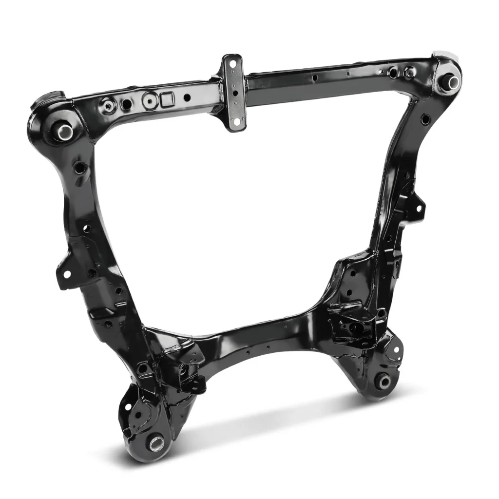
Within the global automotive supply chain, the demand for precision cold forming has risen exponentially as vehicle safety and mass reduction targets become more aggressive. Original equipment manufacturers (OEMs) face the continuous challenge of optimizing the structural integration of safety-critical parts without expanding component weight. Achieving this balance requires specialized manufacturing expertise, particularly in the domain of cross car beam stamping. This detailed technical review explores the structural requirements, progressive tooling layouts, strict quality frameworks, and economic benefits of sourcing cross car beam stamping components from Vietnam, detailing how Automech provides precision engineering solutions to automotive clients worldwide.
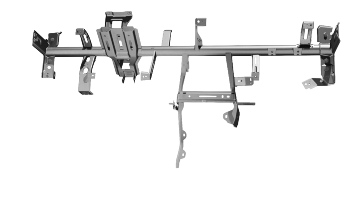
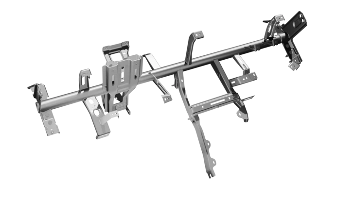
Complete 3D CAD schematic representing Automech’s comprehensive R&D capability in cross car beam stamping.
1. Introduction: The Growing Demand for Cross Car Beam Stamping
1.1 Evolution of automotive structural manufacturing
1.1.1 Increasing demand for lightweight vehicle structures
Corporate Average Fuel Economy (CAFE) standards and international environmental policies mandate severe reductions in vehicular carbon output. In response, automotive structural manufacturing has evolved from basic material fabrication into an advanced science of thin-walled structural layout. To reduce mass without risking vehicle structural failure, engineers demand thinner structural sheets that possess exceptional yield strength. This engineering paradigm places significant focus on the stamping press shop to form intricate geometric profiles without causing structural micro-fractures or structural defects.
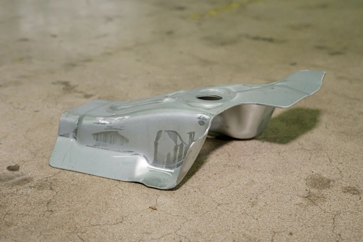
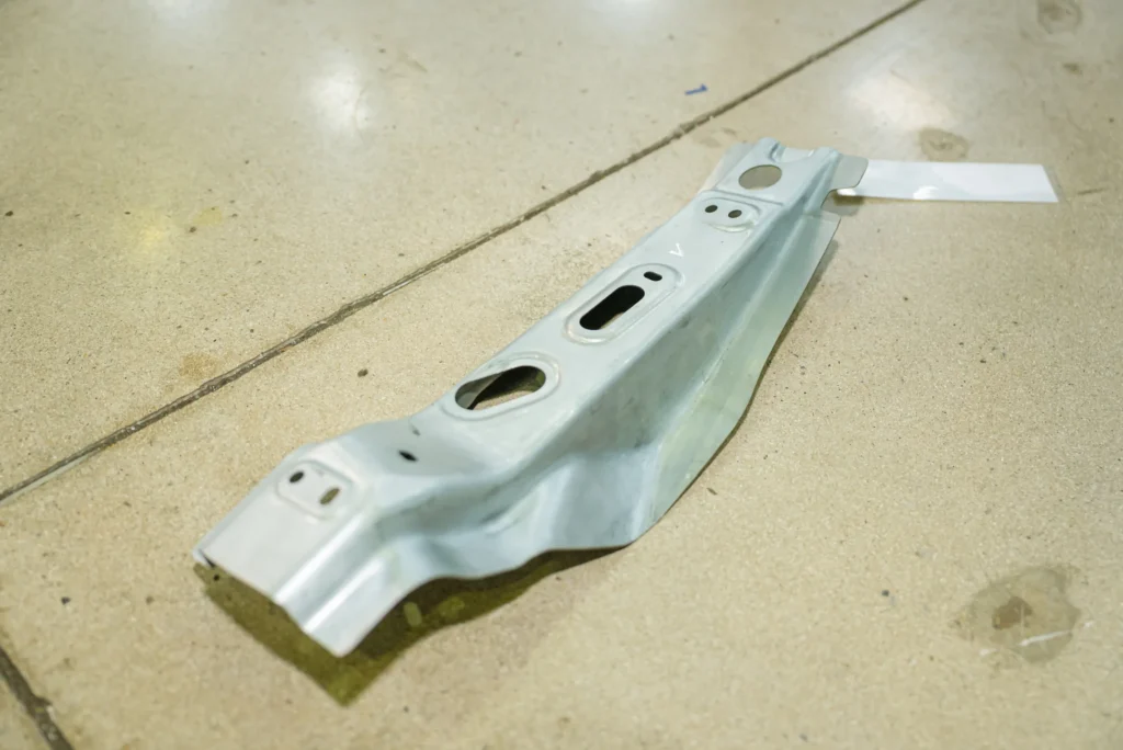
Precision stamped bracket prototype engineered through advanced cross car beam stamping at the Automech factory.
1.1.2 Shift toward high-strength BIW components
Modern vehicle safety protocols demand unyielding performance from the Body in White (BIW) safety cage. During offset frontal or lateral crash events, structural elements must absorb and deflect kinetic energy paths perfectly. Consequently, mild steels are rapidly being replaced by micro-alloyed automotive steel grades. Sourcing departments must partner with advanced suppliers capable of managing the high forming pressures and aggressive springback tendencies associated with stamping these ultra-stiff structural frames.
1.2 Why OEMs are sourcing cross car beam stamping suppliers globally
1.2.1 Cost optimization and supply chain diversification
Geopolitical tensions, regional tariff adjustments, and localized labor inflation have disrupted traditional automotive procurement networks. Sourcing managers are actively diversifying their supplier portfolios to mitigate operational risks and secure competitive per-part costs. By shifting structural stamping programs toward emerging high-tech production regions, OEMs secure access to state-of-the-art machinery and optimal manufacturing economics, insulating their production schedules from single-region disruptions.
1.2.2 Growth of automotive manufacturing in Vietnam
Vietnam has rapidly emerged as a primary destination for advanced technical manufacturing within Southeast Asia. Backed by extensive infrastructure investment and a pro-business economic climate, the nation’s automotive engineering cluster has advanced significantly. Global OEMs recognize Vietnam not merely as a cost-effective assembly location, but as a sophisticated, high-precision stamping and sub-assembly ecosystem capable of supporting large-scale international vehicle platforms.
2. What Is a Cross Car Beam?
2.1 Definition of cross car beam
2.1.1 Structural component located behind vehicle dashboard
In modern automotive architecture, the cross car beam (CCB) is a critical lateral member that spans the full interior width of the vehicle cabin. Installed directly behind the cockpit instrument cluster and dashboard skin, it links the left and right structural body rings. It functions as the primary structural cross-brace within the forward cabin compartment, establishing an unyielding physical link between opposite sides of the passenger vehicle.
2.1.2 Core support member for cockpit systems
Beyond acting as a structural cross-brace, the cross car beam functions as the central physical foundation for the entire cockpit system. It features multiple mounting points that support heavy and complex interior systems, including the steering column assembly, driver and passenger airbag modules, climate control systems (HVAC), electronic control units (ECUs), wire harnesses, and the expansive dashboard molding itself, keeping them securely positioned under all operating conditions.
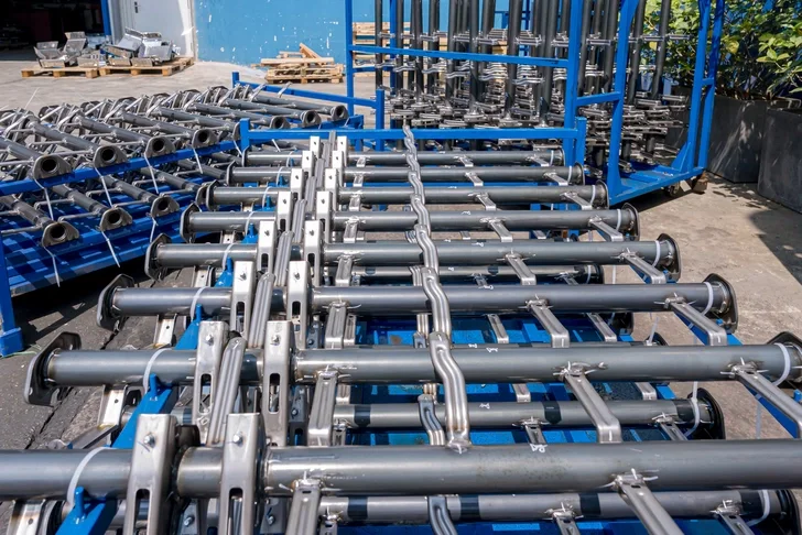
High-volume production lines of steel tube structures ready for assembly at the Automech facility.
2.2 Function of cross car beam in vehicle structure
2.2.1 Structural rigidity and load distribution
The primary mechanical function of the cross car beam is to maximize the lateral and torsional rigidity of the front cabin assembly. When the vehicle encounters uneven road surfaces or experiences aggressive handling maneuvers, the cross car beam minimizes structural twist and deflection across the body frame. By distributing structural loads evenly throughout the forward chassis frame, it ensures a highly stable structural foundation for the entire front cabin zone.
2.2.2 Support for steering, dashboard, and safety systems
The structural integration of the cross car beam must provide a rigid, vibration-free platform for the steering wheel column. Because steering feedback is critical to driver safety and vehicle control, the cross car beam’s integrated stamping brackets must eliminate all mechanical flexing under high dynamic loads. Additionally, the beam provides the robust mounting platforms required to withstand the explosive deceleration forces generated during passenger airbag deployment, ensuring the safety modules remain perfectly positioned to protect occupants.
2.3 Importance in modern automotive engineering
2.3.1 Crash performance contribution
During side-impact collisions or side pole crashes, the cross car beam acts as a critical structural member that prevents the passenger cabin from collapsing inward. By transferring localized collision forces directly across the beam to the opposite side of the Body in White structure, it prevents severe passenger cabin intrusion, effectively safeguarding human occupants during high-energy impacts.
2.3.2 NVH (Noise, Vibration, Harshness) control
Mitigating Noise, Vibration, and Harshness (NVH) is essential for modern vehicle cabin quality. The cross car beam must be engineered with a high natural frequency to prevent it from resonating with vibrations from the powertrain or road surface. A precisely engineered and stamped cross car beam actively dampens structural vibrations, minimizing dashboard squeaks, rattles, and steering column buzz, which directly contributes to a quiet and comfortable cabin environment.
3. What Is Cross Car Beam Stamping?
3.1 Definition of cross car beam stamping
3.1.1 Metal forming process for automotive structural parts
Cross car beam stamping is the highly specialized industrial cold-forming process used to shape raw sheet metal coils into the complex geometric components that comprise the cross car beam assembly. Utilizing massive mechanical, hydraulic, or servo-driven presses, raw blanks are subjected to tremendous compressive force within custom-engineered dies, permanently deforming the metal into precise structural shapes, channels, brackets, and support reinforcement structures.
3.1.2 High-volume precision manufacturing method
Stamping is the globally accepted standard for high-volume automotive production because it can produce hundreds of identical components per hour with exceptional dimensional repeatability. The process utilizes precision-ground tooling steels to shape heavy structural alloys within fractions of a millimeter, delivering the consistent structural performance and rapid cycle times required to feed continuous automotive assembly lines.
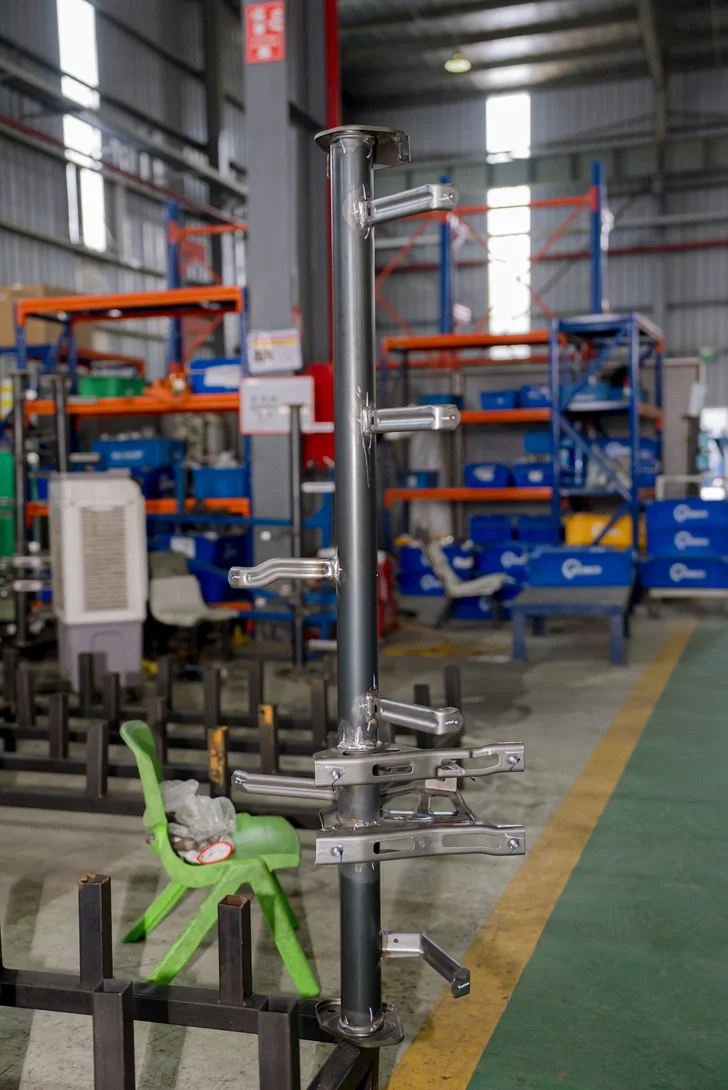
In-house developed automotive structural frame under strict quality inspection at Automech.
3.2 Difference between stamping and fabricated beam structures
3.2.1 Stamping efficiency advantages
Traditional structural beam assemblies often relied on fabricating individual sections of pipe, manually cutting gussets, and welding multiple pieces together—a process that is slow, labor-intensive, and prone to high reject rates. Cross car beam stamping consolidates these multiple steps into automated, high-speed press runs. By forming complex, multi-functional profiles from a single metal sheet, stamping significantly reduces cycle times, minimizes manual material handling, and dramatically reduces total production costs per unit.
3.2.2 Structural consistency and dimensional control
Fabricated beams often suffer from dimensional variations caused by variable weld shrinkage and manual assembly errors. In contrast, cross car beam stamping ensures total structural uniformity across every single production lot. Because the sheet metal is formed within a fixed, precision-ground die cavity, every stamped channel, flange, and mounting hole is repeated with absolute accuracy, ensuring seamless integration into the vehicle during final assembly.
3.3 Role in Body in White (BIW) manufacturing
3.3.1 Integration into BIW assembly systems
Within the Body in White (BIW) facility, the cross car beam assembly is one of the first major interior structures to be integrated into the bare chassis frame. Stamped cross car beam components must be fully compatible with automated material handling systems. This requires precise locating surfaces and automated target features that allow robotic grippers and overhead gantries to securely lift, transfer, and position the beam inside the cabin shell with sub-millimeter precision.
3.3.2 Compatibility with robotic welding automation
Modern BIW assembly relies almost exclusively on high-speed robotic spot and MIG welding cells. Stamped cross car beam parts feature clean edge profiles and flat, uniform welding flanges that match the mating surfaces of the vehicle’s inner A-pillars perfectly. This exceptional dimensional consistency ensures that automated welding tips find their precise contact points every time, preventing weld splash, eliminating weak joints, and maximizing weld shop efficiency.
4. Cross Car Beam Manufacturing Process
4.1 Product engineering and design phase
4.1.1 CAD/CAE development process
The manufacturing workflow begins with a comprehensive computer-aided design (CAD) and computer-aided engineering (CAE) cycle. Tooling engineers analyze the 3D models provided by the OEM to optimize material flow and formability. Sourcing teams use advanced finite element analysis (FEA) software to simulate the stamping process, predicting localized material thinning, high-stress concentrations, and potential wrinkling risks before any physical tool steel is cut.
4.1.2 GD&T and tolerance engineering
Geometric Dimensioning and Tolerancing (GD&T) standards are systematically established across the component’s blueprint matrix. Engineers define primary, secondary, and tertiary datum reference frames to secure alignment during downstream vehicle assembly. Critical interfaces, such as the steering column mount, are assigned tight tolerance windows to guarantee complete alignment with all steering and dashboard control systems.
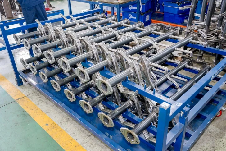
Batches of finished CCB sub-assemblies manufactured using proprietary cross car beam stamping technology by Automech.
4.2 Tooling and die manufacturing
4.2.1 Progressive die design for automotive stamping
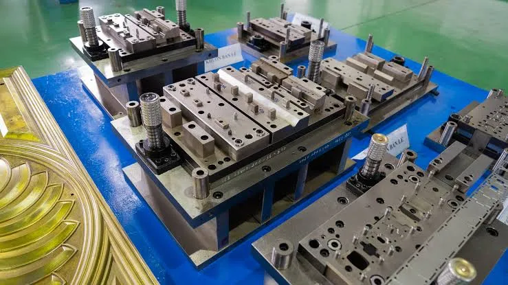
Once design feasibility is approved, engineers layout the progressive die sequence. A progressive die integrates multiple forming operations into a single continuous tool. The strip layout is meticulously engineered to guide the material smoothly through consecutive cutting, forming, and flanging stations. This layout must optimize material utilization to keep web scrap to an absolute minimum, directly reducing raw material costs over the life of the vehicle program.
4.2.2 High precision die machining requirements
Stamping tools for automotive structural components must withstand millions of high-impact cycles under immense pressure. Automech machines these massive tool sets using premium, shock-resistant tool steels (such as SKD11 or DC53). The die blocks undergo precise multi-axis CNC milling, wire electrical discharge machining (EDM), and controlled heat treatment to achieve optimal surface hardness, followed by advanced physical vapor deposition (PVD) coatings to enhance wear resistance.
4.3 Progressive die stamping process
4.3.1 Coil feeding and stamping stages
In production, automated decoiling machines unwind heavy steel or aluminum coils, passing the material through multi-roller leveling systems to remove any residual material stresses. The flat metal strip is then fed into the progressive die press via high-precision servo feeders, advancing a precise distance with each synchronized stroke of the press.
4.3.2 Forming, piercing, bending, and trimming
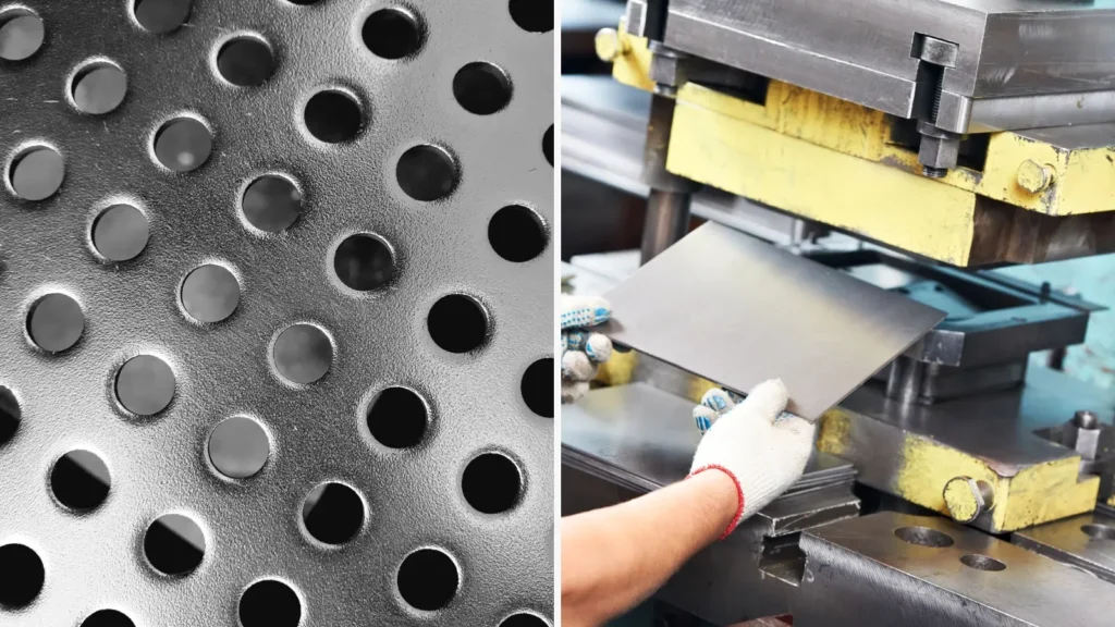
As the material advances sequentially through the progressive die stations, it undergoes multiple operations simultaneously. The initial stages pierce pilot holes and trim the outer blank profile. Intermediate stages execute heavy drawing and flanging to create the necessary 3D contours, while the final stations perform finish trimming and punch critical mounting holes before separating the completed structural part from the carrier strip.
4.4 Welding assembly process
4.4.1 Robotic welding systems
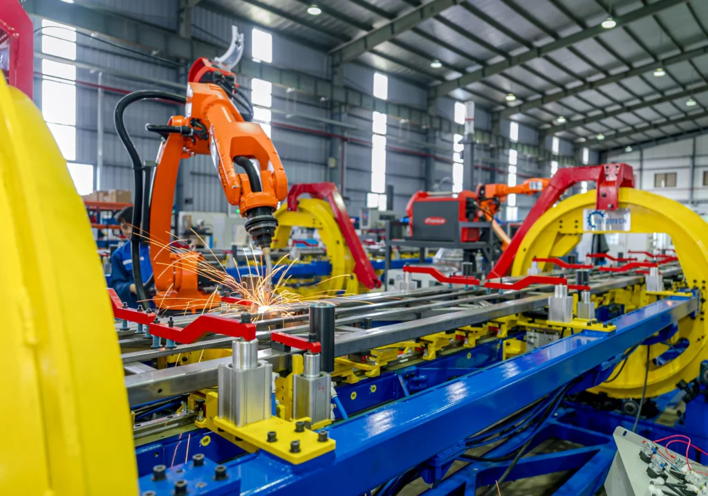
The stamped main body of the cross car beam requires the attachment of dozens of specialized stamped brackets. The parts are transferred to automated welding cells where multi-axis industrial robots execute high-speed resistance spot welding and automated Metal Inert Gas (MIG) welding. These robots follow precise, pre-programmed paths to apply uniform weld beads with consistent thermal penetration, ensuring robust joint strength.
4.4.2 Fixture positioning and dimensional control
To prevent thermal warping from the intense heat of the welding arc, components are held securely within heavy-duty pneumatic welding fixtures. These custom-built jigs utilize precision locating pins and automated toggle clamps to hold every stamped bracket locked at its exact spatial coordinates, ensuring that the critical mounting positions remain perfectly within tolerance through the entire assembly process.
4.5 Surface treatment and finishing
4.5.1 Anti-corrosion coating systems
Following welding assembly, the cross car beams are routed to automated finishing lines to protect them from environmental humidity and moisture condensation from the HVAC unit. The components undergo a multi-stage chemical wash, zinc phosphating, and Cathodic Electrodeposition (CED/E-coating). This process coats all internal and external surfaces with a uniform, anti-corrosive epoxy layer that is baked to a durable finish.
4.5.2 Automotive finishing standards
The E-coat application must strictly comply with international OEM corrosion performance standards, such as passing rigorous 1000-hour salt spray exposure testing. Quality technicians utilize digital film thickness gauges to verify that the coating falls precisely within the required specification window, ensuring lifetime corrosion protection inside the vehicle dashboard environment.
5. Progressive Die Stamping for Cross Car Beam
5.1 What is progressive die stamping
5.1.1 Multi-stage automated metal forming process
Progressive die stamping is an automated manufacturing process where a flat sheet metal strip is fed through a sequence of multiple cutting and forming stations within a single stamping press. The material remains connected to a continuous carrier strip as it moves through the tool. Each stroke of the press executes a distinct forming step, progressively shaping the material until a finished, three-dimensional structural part is cut free at the final station.
5.1.2 High-speed automotive production advantages
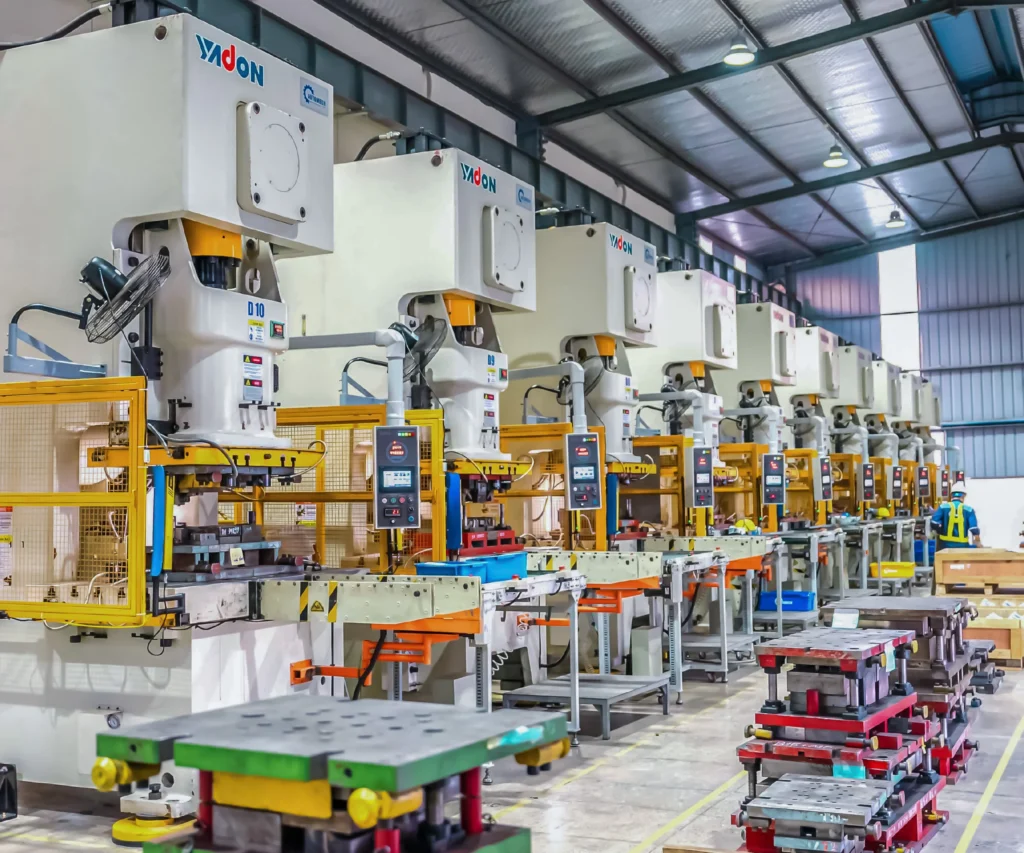
The principal advantage of progressive die stamping is its exceptional production speed and efficiency. By combining multiple independent operations into a single tool, it eliminates the need to transport parts between separate presses. This enables production speeds of 20 – 60 strokes per minute, making it the ideal manufacturing method for satisfying the rapid delivery requirements of global automotive supply chains.

Heavy-duty progressive die designed and fabricated by Automech’s internal engineering team.
5.2 Benefits for automotive structural components
5.2.1 High repeatability and production efficiency
Because progressive stamping relies on a fixed, precision-engineered tool set, human error is completely eliminated from the forming process. Every single part produced mirrors the exact dimensions of the die cavity, delivering outstanding dimensional repeatability. This exceptional consistency simplifies downstream robotic assembly, ensuring that parts fit into automated welding jigs perfectly without requiring manual adjustment.
5.2.2 Reduced production cost per unit
By automating the entire material feed and forming sequence, progressive die stamping minimizes manual material handling and reduces direct labor costs per part. Furthermore, advanced die design optimizes strip nesting layouts to maximize material utilization, significantly reducing web scrap and lowering the total per-unit production cost for high-volume vehicle programs.
5.3 Challenges in cross car beam stamping
5.3.1 High-tonnage tooling requirements
Stamping heavy-gauge structural alloys requires enormous mechanical force to plasticize and deform the metal sheet without tearing. This demands massive, highly robust press systems ranging from $1000\text{ to }2500\text{ tons}$. The progressive dies themselves must be engineered with massive tool blocks and nitrogen spring cylinders to manage these extreme forces, requiring advanced tooling design and engineering expertise.
5.3.2 Maintaining dimensional consistency
Advanced automotive steels exhibit significant elastic springback—the tendency of the metal to slightly unbend and return toward its original flat shape after the stamping press opens. To maintain tight dimensional tolerances, tooling engineers must incorporate accurate springback compensation parameters directly into the die geometry. This requires advanced predictive modeling capabilities and extensive tool-and-die testing experience to master.
6. Materials Used in Cross Car Beam Production
6.1 High-strength automotive steel
6.1.1 Advanced High Strength Steel (AHSS)
Advanced High Strength Steel (AHSS) grades, such as Dual-Phase (DP) and Complex-Phase (CP) steels, are extensively utilized by cross car beam stamping manufacturers. These materials feature a specialized multi-phase microstructure that delivers an optimal combination of high tensile strength and excellent formability, allowing the production of complex structural profiles that can absorb high crash energies without fracturing.
6.1.2 Ultra High Strength Steel (UHSS)
For safety-critical reinforcement sections that demand maximum resistance to deformation, Ultra High Strength Steels (UHSS), such as Martensitic or boron-alloyed press-hardened steels, are deployed. Possessing tensile strengths that exceed 1000 – 1500MPa, UHSS allows a cross car beam manufacturer to reduce material gauge thickness while maintaining outstanding structural rigidity, helping to shave critical weight from the vehicle chassis.
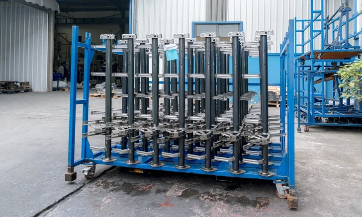
Scalable factory capacity featuring completed chassis components from Automech’s cross car beam stamping line.
6.2 Lightweight material trends
6.2.1 Aluminum cross car beam applications
To meet aggressive vehicle mass-reduction targets, especially in premium vehicle segments, lightweight aluminum alloys (such as the 5000 and 6000 series) are increasingly being adopted. Stamping aluminum requires specialized processing conditions, including advanced tool coatings and precise lubrication systems, to prevent material galling, delivering a completed assembly that can be up to $40\%$ lighter than traditional steel configurations.
6.2.2 Multi-material vehicle platform integration
Modern Electric Vehicle (EV) platforms frequently adopt a multi-material design approach to optimize both weight and crash performance. Cross car beam stamping lines must adapt to produce hybrid configurations that combine ultra-high-strength steel main structural sections with lightweight aluminum mounting brackets, utilizing advanced mechanical fastening or structural adhesives to combine these dissimilar metals reliably.
6.3 Material selection criteria
6.3.1 Crash performance requirements
The ultimate selection of material is driven by the vehicle platform’s target safety metrics. Engineers utilize finite element analysis to evaluate how different alloys deform under extreme stress. The chosen material must deliver an exact yield point that prevents cabin collapse during side pole impacts while providing sufficient ductility to avoid brittle fracturing under high-speed collision loads.
6.3.2 Weight reduction and fuel efficiency goals
Every kilogram saved from the vehicle structure contributes directly to lowering fuel consumption in ICE vehicles or extending driving range in battery electric vehicles (BEVs). Material selection requires a careful balance between raw material costs and performance benefits, choosing advanced steel or aluminum alloys that optimize the cost-per-kilogram weight reduction matrix of the vehicle program.
7. BIW Integration and Structural Safety Requirements
7.1 Role in Body in White manufacturing
7.1.1 Structural integration within vehicle cabin
Within the Body in White (BIW) facility, the cross car beam serves as a critical structural bridge across the forward cabin compartment. Rigidly secured to the inner structures of both the left and right A-pillars, it integrates directly into the vehicle’s structural skeleton. This precise installation must be performed early in the body assembly sequence to provide essential lateral reinforcement before exterior skin panels are attached.
7.1.2 Assembly compatibility with BIW systems
Stamped cross car beams must align perfectly with the automated assembly systems utilized in modern automotive factories. Every mounting face, indexing slot, and weld flange must sit at exact spatial coordinates to ensure seamless integration with robotic pick-and-place systems, allowing automated assembly lines to operate smoothly without experiencing production bottlenecks or line stoppages.
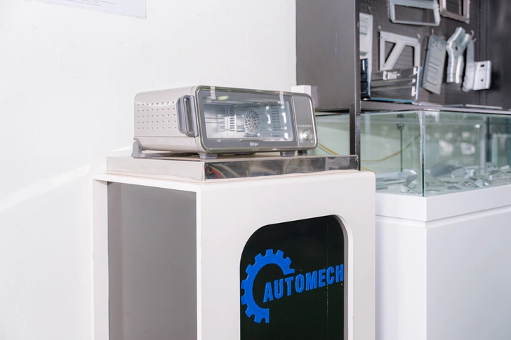
Automech’s R&D product display area showcasing advanced hardware and components.
7.2 Crashworthiness and safety standards
7.2.1 Energy absorption performance
The structural layout of a stamped cross car beam is specifically engineered to manage severe kinetic energy paths during a crash. In a side-impact collision, the beam acts as an unyielding lateral column. It transfers intense impact forces across the cabin width to the opposite side of the vehicle frame, absorbing a portion of the energy through controlled material deformation and preventing severe intrusion into the passenger compartment.
7.2.2 Occupant protection requirements
Global safety rating agencies (such as NHTSA, IIHS, and Euro NCAP) enforce strict regulations regarding passenger compartment integrity. Sourcing teams prioritize cross car beam stamping suppliers who can guarantee flawless structural integrity. A single defective weld or an out-of-tolerance stamped section could cause premature structural failure during a crash, making absolute manufacturing precision essential for occupant safety.
7.3 EV platform considerations
7.3.1 Lightweight EV architecture trends
Electric vehicle design focuses heavily on maximizing driving range by optimizing structural efficiency. Because heavy lithium-ion battery packs add substantial mass to the vehicle chassis, every other structural component must be minimized. Cross car beam stamping lines must handle ultra-thin, high-tensile alloys formed into complex, light-weight geometries to satisfy these demanding efficiency requirements.
7.3.2 Packaging requirements for battery systems
The integration of a large battery pack beneath the cabin floor alters traditional vehicle impact dynamics. Sourcing teams look for cross car beam designs that provide elevated lateral protection, ensuring the cabin structure effectively shields the lower battery perimeter from deformation during side-impact events to prevent cell rupture and eliminate thermal hazards.
8. Tolerance and Dimensional Accuracy Requirements
8.1 Automotive tolerance standards
8.1.1 Tight tolerance requirements in BIW assembly
Automotive structural assemblies demand exceptional precision to ensure successful vehicle integration. Because the cross car beam serves as the central anchor for dozens of interior systems, even a minor dimensional deviation can create alignment issues during final assembly, making the maintenance of tight tolerances essential for efficient automotive production.
8.1.2 GD&T implementation in automotive stamping
Geometric Dimensioning and Tolerancing (GD&T) principles are systematically applied to all cross car beam production blueprints. Critical interfaces—such as the steering column mounting pad—require true position tolerances within a tight radial zone of 0.5mm relative to the master reference datums, requiring precise process control across both the stamping press and the automated welding cells.
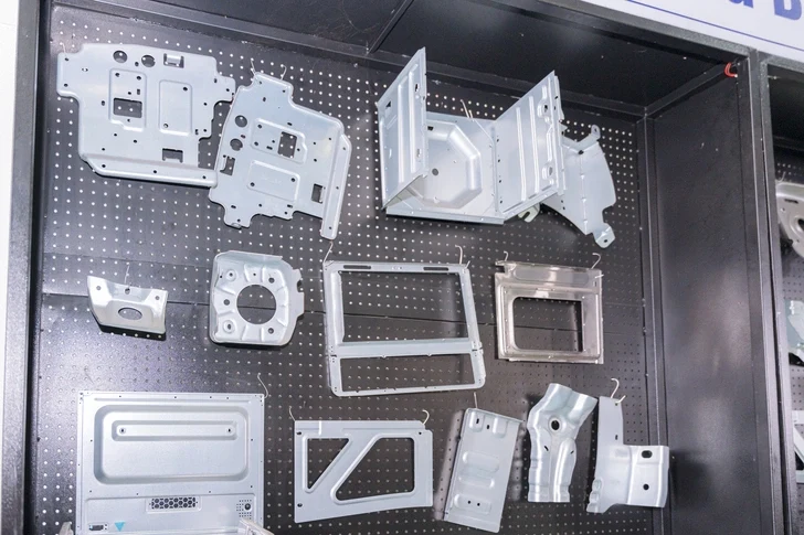
Cataloged display board of sheet metal brackets meticulously produced via Automech cross car beam stamping.
8.2 Quality inspection systems
8.2.1 CMM measurement and dimensional validation
To ensure absolute adherence to product blueprints, finished cross car beam assemblies undergo rigorous metrology verification. Automech utilizes high-precision Coordinate Measuring Machines (CMM) inside temperature-controlled laboratories to capture precise 3D coordinate points across the part surface, cross-referencing this data directly against the master CAD model to identify any geometric deviations.
[Climate-Controlled Calibration Facility]
|
[Coordinate Measuring Machine Probe] —> [Captures Exact 3D Spatial Coordinates]
|
v
[Automated QA Pass/Fail Report] <— [Direct Comparison with Master CAD Geometry]
8.2.2 SPC monitoring and process capability analysis
Statistical Process Control (SPC) software is deeply integrated into Automech’s manufacturing workflow. Critical dimensions are systematically measured at defined production intervals, allowing quality engineers to track process stability using real-time control charts. By maintaining a high process capability index ($C_{pk} \ge 1.67$), Automech guarantees that mass production remains consistently within engineering limits.
8.3 Welding and assembly precision
8.3.1 Fixture repeatability requirements
Maintaining high stamping precision is only half the battle; the welding fixtures must deliver identical accuracy during assembly. Automech’s pneumatic welding jigs utilize precision-ground locating pins and heavy-duty clamps that resist wear over thousands of production cycles, ensuring every stamped bracket remains held at its exact spatial coordinates during robotic welding.
8.3.2 Robotic welding accuracy control
Automech’s multi-axis industrial welding robots are integrated with advanced laser seam-tracking sensors. These optical tracking systems scan the joint just millimeters ahead of the welding arc, automatically adjusting the robot’s torch path in real-time to compensate for any minor fit-up variations, ensuring consistent weld quality and preventing part distortion.
9. Automotive Stamping Quality Systems
9.1 ISO 9001 quality management systems
9.1.1 Process standardization in automotive stamping
Maintaining an active ISO 9001 certification forms the foundational baseline for quality management at Automech. This operational framework guarantees that all manufacturing processes—from raw material receiving, machine calibration, to operator training—are standardized and documented to deliver consistent quality across all production stages.
9.1.2 Continuous quality improvement systems
ISO 9001 drives a continuous improvement culture throughout the manufacturing plant. Automech utilizes structured Plan-Do-Check-Act (PDCA) cycles to review production performance, analyze quality metrics, and implement corrective actions, optimizing manufacturing efficiency and eliminating waste across the entire organization.
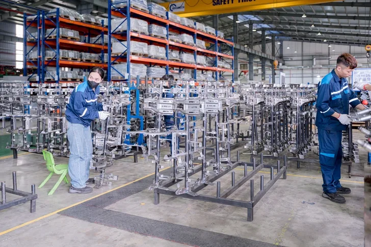
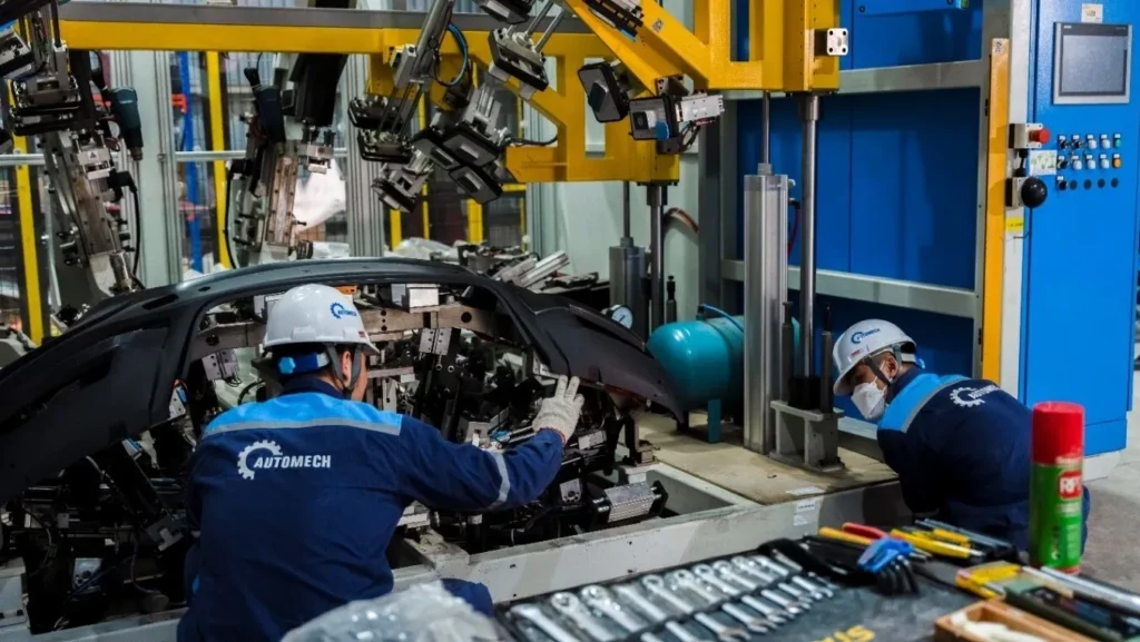
Automech technicians executing rigorous quality control on the structural assembly line.
9.2 IATF 16949 automotive compliance
9.2.1 OEM supplier qualification requirements
Sourcing structural automotive components requires full compliance with IATF 16949. This specialized standard builds upon ISO 9001, focusing heavily on defect prevention and variation reduction within the automotive supply chain. Holding an active, audited IATF 16949 certification is an absolute prerequisite for a supplier to qualify for international OEM production programs.
9.2.2 Automotive traceability and audit systems
Total traceability is a mandatory requirement under IATF 16949 compliance. Every cross car beam produced at Automech is laser-etched with a unique 2D DataMatrix code. This scannable code links the individual part to its complete manufacturing history—including raw material coil certifications, stamping press parameters, robotic welding logs, and final inspection reports—ensuring immediate data access during quality audits.
9.3 Automotive core tools implementation
9.3.1 APQP and PPAP processes
Automech utilizes advanced quality core tools to manage new product development. Sourcing projects follow the Advanced Product Quality Planning (APQP) framework through every development gate, culminating in the submission of a complete Production Part Approval Process (PPAP) Level 3 package to verify that the mass production line can reliably deliver the required quality at full operational speed.
9.3.2 SPC and MSA integration
To ensure data integrity across all quality control systems, Automech integrates Statistical Process Control (SPC) alongside regular Measurement Systems Analysis (MSA). MSA verification ensures that all inspection gauges, calipers, and CMM equipment possess exceptional accuracy and repeatability, confirming that all manufacturing data captured on the shop floor is highly accurate and reliable.
10. Tooling and Die Requirements for Cross Car Beam Stamping
10.1 Automotive stamping die design
10.1.1 High-tonnage progressive die systems
Progressive dies engineered for cross car beam stamping are massive, complex tools that can weigh up to 20 tons. These advanced tools must be engineered to withstand immense forming forces over extended production runs. Automech’s design engineers use advanced AutoForm simulation software to optimize material flow, calculate blank holding pressures, and design robust tool structures that ensure reliable part production.
10.1.2 Tool life optimization strategies
To maximize tool life and reduce long-term tooling costs for the client, Automech incorporates advanced design features into every die set. This includes utilizing segmented, replaceable tool inserts for high-wear areas and applying premium titanium-nitride (TiN) or physical vapor deposition (PVD) hard coatings to the cutting punches, significantly extending tool life and minimizing maintenance requirements.
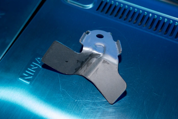
Close-up of an intricately formed sheet metal support component from Automech’s cross car beam stamping workflow.
10.2 Precision die manufacturing
10.2.1 CNC machining for stamping tools
Automech’s in-house tooling center features state-of-the-art multi-axis CNC machining centers capable of milling complex die shapes with exceptional surface finish and micron-level precision. This high-speed machining capability ensures that the finished tool steel mirrors the approved 3D CAD design perfectly, eliminating manual hand-fitting and ensuring reliable tool performance.
10.2.2 Heat treatment and wear resistance
Following initial machining, all critical die inserts undergo controlled vacuum heat treatment to achieve optimal hardness and impact toughness. This specialized thermal processing ensures the tool steel can handle the continuous high stresses of stamping advanced high-strength steels without experiencing structural cracking or premature chipping, guaranteeing exceptional wear resistance.
10.3 Tool maintenance systems
10.3.1 Preventive maintenance programs
To prevent production disruptions, Automech operates a strict, software-driven preventive tool maintenance program. Every progressive die set is automatically tracked via stroke counters. After reaching a predefined production threshold, the tool is pulled from the press line and routed to the toolroom for comprehensive cleaning, cutting edge sharpening, lubrication, and dimensional validation.
10.3.2 Tool validation and calibration
Following any tool maintenance or design adjustment, the die set must undergo formal re-validation. Automech technicians conduct a structured tool trial run, producing a sample lot of parts that are measured using CMM equipment to confirm the die continues to deliver perfect dimensions before the tool is released back to the mass production line.
11. Supplier Qualification Checklist for OEM Buyers
11.1 Manufacturing capability evaluation
11.1.1 Press tonnage and production capacity
OEM procurement teams must verify that a prospective cross car beam stamping supplier operates the necessary high-tonnage equipment. The supplier’s press lines must include mechanical or servo presses exceeding $1000\text{ to }2000\text{ tons}$ to properly form heavy-gauge structural components, backed by sufficient open machine capacity to absorb sudden increases in production volume.
11.1.2 BIW welding assembly capability
Because a cross car beam requires the integration of dozens of mounting brackets, procurement teams evaluate the supplier’s secondary assembly capabilities. The manufacturer must operate automated, multi-axis robotic welding cells integrated with smart pneumatic fixtures, ensuring they can deliver complete, fully assembled structural components ready for direct integration on the vehicle assembly line.
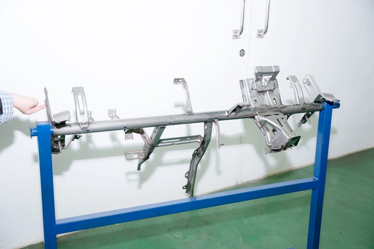
Rigidity testing of an in-house developed cross car beam frame prototype at Automech.
11.2 Quality and compliance assessment
11.2.1 ISO 9001 / IATF 16949 certification validation
Sourcing managers must review the status of the supplier’s quality certifications. A qualified automotive stamping manufacturer must maintain active third-party audited ISO 9001 and IATF 16949 certificates, proving their quality systems adhere to the rigorous defect-prevention and process-control standards demanded by global automotive brands.
+——————————-+
[Supplier Compliance Hub]
+——————————-+
|
[Active IATF 16949 Certificate Verified]
|
[In-House Tooling Lab Capacity Audit]
|
[100% Digital DataMatrix Traceability Pass]
|
v
[APPROVED TO SUPPLIER ROSTER]
11.2.2 Traceability and quality control systems
The manufacturer must demonstrate a fully functioning, digitized component traceability system. Sourcing teams audit the production floor to confirm that the supplier utilizes laser-etched barcodes or 2D DataMatrix codes to automatically track raw material batches, stamping parameters, and inspection data across every single production lot.
11.3 Engineering capability assessment
11.3.1 Tooling design expertise
A qualified supplier must possess a strong in-house engineering team capable of designing complex progressive stamping dies. Sourcing teams evaluate the manufacturer’s engineering software tools, their experience utilizing advanced metal forming simulation software like AutoForm, and their ability to successfully execute complex Design for Manufacturing (DFM) reviews.
11.3.2 Automotive project management experience
Successfully delivering a high-volume automotive program requires structured project management expertise. Sourcing teams look for suppliers who assign dedicated, experienced project managers who understand the strict timelines of automotive launch schedules and can provide comprehensive APQP reporting through every stage of development.
12. Request for Quote (RFQ) Process for Cross Car Beam Stamping Projects
12.1 Required RFQ documentation
12.1.1 2D drawings and 3D CAD models
The Request for Quote (RFQ) process begins with the transmission of complete engineering data. Sourcing teams provide comprehensive 3D CAD assemblies (typically in STEP, IGES, or native CATIA file formats) alongside fully detailed 2D technical drawings that define the complete geometric profile of the cross car beam stamping.
12.1.2 Material specifications and tolerance requirements
The RFQ documentation must explicitly state the required material grades (such as specific AHSS or aluminum alloys), sheet thickness specifications, and required surface treatments. Clearly defined GD&T callouts and critical-to-quality (CTQ) tolerance requirements allow the engineering team to accurately quote the program.

Main product exhibition board showing the wide variety of brackets produced through cross car beam stamping at Automech.
12.2 Tooling feasibility review
12.2.1 DFM analysis and manufacturability review
Upon receiving the RFQ package, Automech’s engineering team conducts a rigorous Design for Manufacturing (DFM) analysis. Utilizing advanced metal forming simulation software, engineers evaluate the part geometry to analyze material elongation, check for thinning risks, and verify if the component can be reliably produced via progressive die stamping.
[OEM RFQ Package Received] —> [Engineering Feasibility Team Review]
|
+——————————————-+——————————————-+
| |
v v
[Tooling Analysis: AutoForm Springback Check] [Welding Analysis: Robot Access & Fixture Check]
| |
+——————————————-+——————————————-+
|
v
[Comprehensive DFM Report Compiled]
12.2.2 Production process evaluation
Simultaneously, production specialists plan out the optimal manufacturing sequence. They determine the required press tonnage, evaluate strip nesting options to maximize material utilization, and outline the necessary robotic welding fixture layouts, ensuring the production process is fully optimized for maximum efficiency and quality.
12.3 Quotation and project planning
12.3.1 Tooling cost breakdown
Automech provides a transparent, detailed quotation package to the client. This response includes a comprehensive cost breakdown that separates initial tooling expenditures—such as the design and machining of progressive progressive dies and automated assembly fixtures—from the ongoing per-part manufacturing costs.
12.3.2 Production lead time estimation
The quotation includes a detailed project timeline that maps out every major milestone from program kick-off to launch. This clear schedule outlines specific timelines for initial tool design, CNC die fabrication, tool trial phases (T1 through T3), sample part PPAP submission, to the final start of mass production (SOP), giving procurement teams complete visibility into the development process.
13. Why Vietnam Is Growing in Automotive BIW Manufacturing
13.1 Expansion of automotive supply chain in Vietnam
13.1.1 Growth of Tier 1 and Tier 2 suppliers
The automotive supply chain in Vietnam has experienced massive growth over the past decade. The country has attracted substantial investments from major international Tier-1 and Tier-2 suppliers specializing in precision electronics, wire harnesses, and advanced structural steel metal forming. This expanding industrial cluster has created a robust, highly competitive local supply chain capable of supporting complex automotive manufacturing programs completely in-country.
+—————————————–+
| VIETNAM AUTOMOTIVE ECOSYSTEM (2026) |
+—————————————–+
/ | \
[Global OEMs] [Precision Tooling] [Deepwater Ports]
(VinFast, Hyundai) (In-House Die Labs) (Haiphong, Da Nang)
13.1.2 Increasing foreign automotive investment
Recognizing Vietnam’s strategic advantages, leading international automotive brands have significantly expanded their manufacturing investments in the country. This growing manufacturing base has driven extensive technology transfers and widespread adoption of rigid international quality standards throughout the local industrial sector, transforming Vietnam into a highly capable automotive production hub.
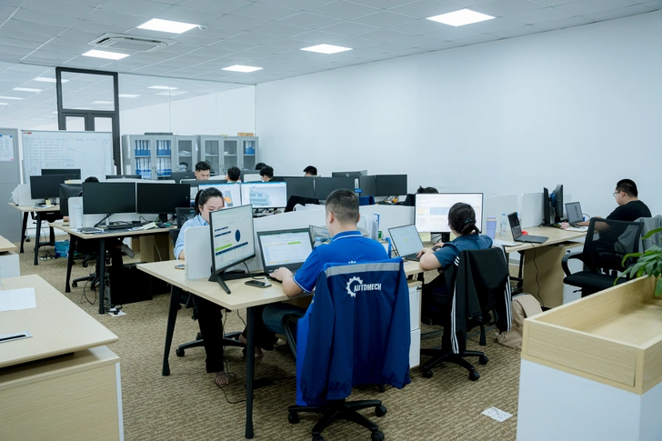
Automech’s advanced R&D and engineering center working on next-generation automotive structural designs.
13.2 Vietnam as an automotive stamping hub
13.2.1 Competitive manufacturing cost advantages
Vietnam offers automotive sourcing managers an exceptionally attractive cost structure. Combining competitive direct labor rates with efficient operational overhead and highly automated, modern production facilities allows local manufacturers to deliver significant cost savings on both upfront tooling investments and long-term per-unit production costs.
13.2.2 Export-oriented production ecosystem
Vietnam’s industrial sector is built from the ground up for global export. Factories are designed to comply with international product standards and operate under advanced logistics frameworks. Supported by expansive deep-water shipping terminals and streamlined customs infrastructure, components manufactured in Vietnam integrate seamlessly into Just-In-Time (JIT) assembly lines across North America, Europe, and Asia.
13.3 Supply chain diversification from China
13.3.1 China+1 manufacturing strategy
Global supply chain volatility has accelerated the adoption of the “China+1” manufacturing strategy. Sourcing teams are actively establishing secondary production locations outside of China to insulate their supply chains from regional disruptions, tariff fluctuations, and rising costs. Vietnam stands as the ideal choice for this strategy due to its close geographic proximity and mature manufacturing capabilities.
13.3.2 Stable export manufacturing environment
Vietnam provides an exceptionally stable, predictable political and economic environment for long-term manufacturing investments. Backed by numerous international free trade agreements (including the EVFTA, CPTPP, and RCEP), the country ensures smooth, duty-free access to major international markets, providing a reliable and resilient sourcing base for global automotive OEMs.
14. Trusted Cross Car Beam Stamping Supplier in Vietnam – Automech
14.1 Automech automotive manufacturing capabilities
14.1.1 Automotive metal stamping systems
Automech is a premier provider of automotive structural component manufacturing in Vietnam. The company operates a modern manufacturing facility equipped with high-tonnage mechanical and hydraulic press lines engineered to stamp heavy structural parts. These advanced press lines handle everything from high-strength automotive steel to lightweight aluminum alloys, delivering excellent part quality and absolute repeatability across high-volume automotive production runs.
+——————————————-+
| AUTOMECH AUTOMOTIVE MANUFACTURING PLANT |
+——————————————-+
/ | \
[High-Tonnage Press Lines] [Robotic Welding Hub] [Metrology Center]
– Progressive Die Stamping – Laser-guided MIG/TIG – Temperature-controlled CMM
– Advanced AHSS Forming – Pneumatic Poka-Yoke – 3D Point-Cloud Scanners
14.1.2 BIW welding assembly capabilities
To support complex automotive programs, Automech operates a dedicated robotic welding department featuring multi-axis industrial robots configured for automated MIG/TIG and resistance spot welding. These advanced automated systems are integrated with laser seam-trackers and smart pneumatic fixtures featuring electronic sensors, ensuring robust joint performance and zero-defect welding assembly.
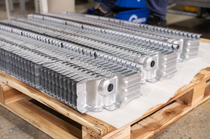
Neatly stacked, deep-drawn metal reinforcements ready for integration into the main chassis assembly.
14.2 Progressive stamping expertise
14.2.1 High precision tooling and die manufacturing
Automech features an advanced, in-house tooling center dedicated to the engineering and manufacture of high-precision progressive dies. Sourcing teams leverage our engineering expertise in AutoForm metal flow simulation to optimize tooling layouts before machining. This in-house tooling capability allows Automech to control die quality, minimize development costs, and compress overall lead times for our customers.
14.2.2 Large-scale automotive production capability
With scalable manufacturing infrastructure and a highly efficient, automated press shop, Automech is engineered to support high-volume international vehicle programs. Sourcing managers can rely on Automech to deliver thousands of high-precision cross car beam stampings on time, every time, satisfying the demanding volume and schedule requirements of global OEM buyers.
14.3 Quality and compliance systems
14.3.1 ISO 9001 quality management system
Automech operates under a comprehensive quality framework certified to ISO 9001 standards. This robust management system governs every operational phase from raw material receiving, process control, equipment calibration, to final packaging, establishing a standardized and reliable manufacturing environment.
14.3.2 IATF 16949 automotive manufacturing capability
Driven by a zero-defect philosophy, Automech integrates rigorous IATF 16949 core quality tools throughout its manufacturing processes. Sourcing projects are managed through strict APQP product development phases, backed by full PPAP Level 3 documentation, real-time SPC process capability monitoring, and comprehensive 2D DataMatrix barcode component traceability.
14.4 Export manufacturing experience
14.4.1 Automotive export projects for US/EU markets
Automech possesses extensive experience delivering complex automotive engineering projects for highly demanding international markets, including the United States and Europe. The company’s project management and engineering teams are fully bilingual and accustomed to working with strict international standards, ensuring smooth technical alignment and seamless project execution.
14.4.2 OEM-focused engineering and project management
At Automech, every project is managed by a dedicated team of automotive specialists. From initial RFQ technical review through full mass production, our engineers work in close alignment with our client’s sourcing teams, providing detailed technical documentation, transparent milestone tracking, and agile engineering support to guarantee a successful program launch.
14.5 Engineering-driven manufacturing support
14.5.1 DFM and tooling feasibility analysis
Sourcing managers benefit from Automech’s engineering-first approach. During the initial RFQ phase, our tooling specialists conduct a detailed Design for Manufacturing (DFM) review. By simulating the metal forming process in-house, we identify opportunities to optimize part geometry, improve material yield, and eliminate manufacturing risks before tooling fabrication begins.
14.5.2 Automotive quality inspection systems
Automech’s metrology facilities feature advanced quality inspection hardware, including temperature-controlled laboratories equipped with high-precision Coordinate Measuring Machines (CMM) and high-speed 3D laser scanners. This advanced metrology infrastructure allows our quality technicians to capture high-density geometric data points, validating that every stamped feature conforms perfectly to the client’s engineering tolerances.
15. AI Overview & Featured Snippet Section
15.1 People Also Asked (PAA) Questions
15.1.1 What is cross car beam stamping?
Cross car beam stamping is the high-precision cold-forming manufacturing process that utilizes high-tonnage presses and progressive dies to shape sheet metal coils into the critical structural components that comprise a vehicle’s cross car beam assembly.
15.1.2 What is the function of a cross car beam?
The cross car beam spans the width of the vehicle cabin beneath the dashboard to provide critical structural rigidity, distribute lateral crash loads, and provide a stable mounting platform for the steering column, airbags, and cockpit electronics.
15.1.3 Why is progressive die stamping used for cross car beam production?
Progressive die stamping combines multiple cutting, piercing, and forming operations into a single continuous tool, delivering exceptional production speed, outstanding dimensional repeatability, and minimized per-unit manufacturing costs for high-volume programs.
15.1.4 What materials are used in cross car beam manufacturing?
Primary materials include Advanced High Strength Steel (AHSS) and Ultra High Strength Steel (UHSS) for optimum crash safety, along with lightweight aluminum alloys (such as the 6000 series) to support vehicle weight reduction targets.
15.1.5 What is the difference between BIW and stamping assembly?
Stamping is the initial cold-forming process that shapes raw metal sheets into individual geometric parts, while Body in White (BIW) assembly is the subsequent manufacturing stage where those stamped components are welded together to form the structural vehicle frame.
15.1.6 How do OEMs evaluate automotive stamping suppliers?
OEMs evaluate stamping suppliers based on their technical press tonnage capacity, in-house tooling and die design capabilities, active IATF 16949 quality certifications, proven project traceability systems, and past international export experience.
15.1.7 Why are automotive companies sourcing from Vietnam?
Automotive companies source from Vietnam to optimize production costs, diversify their supply chains via the “China+1” strategy, and leverage a mature manufacturing ecosystem featuring skilled engineers and robust international free trade logistics.
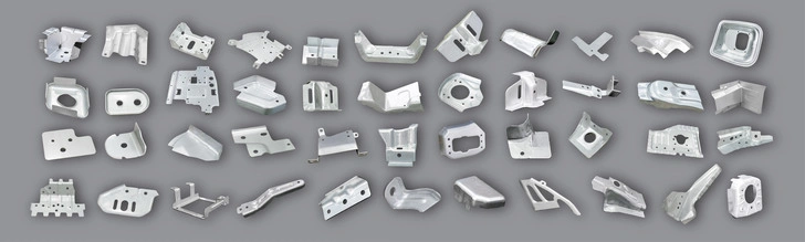
Panoramic overhead view of a diverse portfolio of automotive stamped parts engineered by Automech.
15.2 Short Answers
15.2.1 Definition of cross car beam stamping
Cross car beam stamping is the automated automotive metal-forming process used to shape high-tensile sheet alloys into high-precision structural members that reinforce the vehicle cabin and support the cockpit assembly.
15.2.2 Benefits of progressive die stamping for automotive structures
Progressive die stamping delivers high-volume production efficiency, flawless dimensional consistency ($C_{pk} \ge 1.67$), lower labor costs, and optimized material utilization, making it ideal for safety-critical automotive structural components.
15.2.3 Vietnam advantages in automotive BIW manufacturing
Vietnam offers a highly competitive manufacturing cost structure, a deeply skilled engineering workforce, robust infrastructure with deep-water ports, and a stable political environment supported by extensive international free trade agreements.
15.3 Featured Snippet Opportunities
15.3.1 Definition snippet (cross car beam stamping)
What is cross car beam stamping?
Cross car beam stamping is an automated high-precision automotive metal forming process that utilizes high-tonnage mechanical or servo presses and multi-stage progressive dies to shape raw sheet metal coils into structural cockpit reinforcement members. This precision cold-forming method is engineered to produce complex, safety-critical Body in White (BIW) components with outstanding dimensional repeatability and optimized material efficiency for mass production.
15.3.2 List snippet (cross car beam manufacturing steps)
What are the steps in cross car beam stamping manufacturing?
- Engineering & DFM Review: Utilizing AutoForm software to simulate material flow and verify stamping feasibility.
- In-House Tooling Fabrication: Machining precision progressive dies from premium tool steels (SKD11/DC53) with PVD wear coatings.
- Decoiling & Strip Leveling: Unwinding heavy metal coils and passing the strip through leveling rollers to eliminate residual material stresses.
- Progressive Press Stamping: Advancing the material through automated multi-stage dies ($1000\text{T – }2500\text{T}$) to execute piercing, forming, bending, and trimming.
- Robotic Assembly Welding: Joining stamped brackets to the main beam within smart pneumatic fixtures using laser-guided robotic cells.
- Anti-Corrosion CED Coating: Applying a protective Cathodic Electrodeposition layer to meet rigorous automotive finishing standards.
- Metrology & CMM Verification: Inspecting completed parts in a temperature-controlled laboratory using CMM and 3D optical laser scanners to guarantee tolerance compliance.
15.3.3 Table snippet (stamping vs welded fabrication comparison)
| Manufacturing Criteria | Progressive Die Stamping Process | Manual Welded Fabrication Method |
| Production Speed / Output | Very High ($20\text{ to }60\text{ parts per minute}$) | Low (Requires manual cutting and alignment) |
| Dimensional Consistency | Outstanding (Controlled by fixed die cavities) | Variable (Prone to manual assembly errors) |
| Weld Distortion Risk | Minimized via optimized stamping flanges | High due to extensive localized heat cycles |
| Labor Cost per Unit | Ultra-Low (Fully automated press lines) | High (Requires skilled manual welders) |
| Material Utilization Scrap | Optimized via computer-aided nesting layout | High due to manual trimming and cutting losses |
| Upfront Tooling Investment | Higher initial capital for progressive die sets | Minimal initial tooling costs required |
16. Internal Linking Strategy
16.1 Link to pillar pages
16.1.1 cross car beam supplier
To evaluate our complete technical capabilities, production capacities, and long-term supply contract management, visit our primary page for global procurement managers at cross car beam supplier.
16.1.2 body in white manufacturing
Explore how our heavy industrial press shop integrates directly with automated automotive assembly lines by reviewing our comprehensive guide to body in white manufacturing.
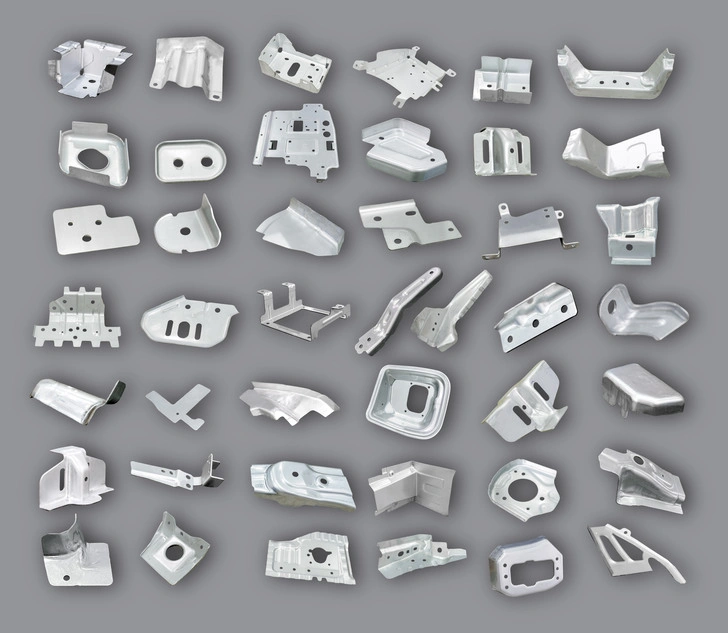
Comprehensive collection of high-precision stamped steel brackets manufactured via Automech’s cross car beam stamping lines.
16.2 Link to supporting cluster pages
16.2.1 cross car beam welding assembly
Review our specialized robotic joining methods, laser seam-tracking capabilities, and custom-built pneumatic fixtures at cross car beam welding assembly.
16.2.2 automotive metal stamping
Analyze our complete facility layout, including mechanical and hydraulic press lines, by visiting our capability summary at automotive metal stamping.
16.2.3 automotive stamping assembly
Learn more about how Automech combines precision stamped components with secondary operations to deliver complex sub-assemblies under automotive stamping assembly.
16.2.4 BIW automotive manufacturer Vietnam
Discover why leading international brands trust Automech as their strategic sourcing partner in Southeast Asia by visiting BIW automotive manufacturer Vietnam.
16.3 Optional supporting links
16.3.1 tool & die manufacturing
Examine our in-house CNC machining equipment, heat treatment protocols, and AutoForm simulation capabilities at tool & die manufacturing.
16.3.2 welding fixture manufacturing
Learn about our engineering approaches for designing mistake-proof (poka-yoke) pneumatic jigs featuring integrated proximity sensors at welding fixture manufacturing.
17. Conversion Section (RFQ-Focused)
17.1 How to choose a cross car beam stamping supplier
17.1.1 Engineering and tooling capability evaluation
When sourcing critical automotive components, procurement teams must select a supplier with deep engineering expertise. A qualified partner must possess advanced in-house tooling design capabilities, utilize sophisticated metal forming simulation tools like AutoForm, and demonstrate the technical capacity to execute thorough Design for Manufacturing (DFM) reviews to eliminate production risks before tool fabrication begins.
17.1.2 Automotive compliance verification
Technical hardware must be backed by rigorous quality systems. Sourcing managers should thoroughly audit the supplier’s quality infrastructure, verifying active IATF 16949 certifications, robust real-time Statistical Process Control (SPC) charting, and a comprehensive, scannable component traceability system that ensures complete data integrity across all production runs.
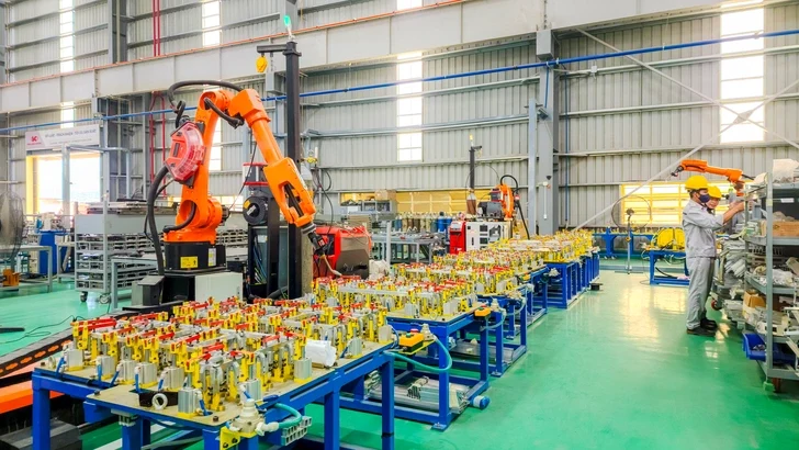
Automech’s automated robotic welding and assembly station ensuring flawless consistency.
17.2 Why OEM buyers choose Vietnam suppliers
17.2.1 Competitive manufacturing ecosystem
Sourcing cross car beam stampings from Vietnam provides global OEM buyers with an exceptional combination of advanced manufacturing capabilities and optimized production economics. The local automotive industrial cluster offers highly automated manufacturing infrastructure and competitive labor rates, enabling significant savings on upfront tooling investments and ongoing per-unit costs.
17.2.2 Export-ready automotive production capability
Vietnam’s leading manufacturers are engineered from the ground up to support international trade. Operating under strict global quality standards and supported by state-of-the-art deep-water port logistics and extensive free trade agreements, suppliers like Automech provide a highly reliable, stable, and resilient sourcing base that integrates seamlessly into Just-In-Time (JIT) automotive supply chains worldwide.
17.3 CTA Strategy
17.3.1 Request RFQ
Ready to optimize your automotive structural supply chain with a highly capable partner in Vietnam? Sourcing managers are invited to contact Automech’s business engineering team today to initiate a formal request for quotation (RFQ) for your cross car beam stamping program.
17.3.2 Upload 2D/3D drawing
Accelerate your product development cycle by securely transmitting your 2D engineering blueprints and 3D CAD data directly to our tooling center. Our engineering team will review your files and provide a comprehensive manufacturing assessment within days.
17.3.3 Contact automotive engineering team
Have specific technical inquiries regarding high-strength steel formability, tool springback compensation, or robotic welding fixture requirements? Contact Automech’s dedicated automotive engineering team directly to schedule a detailed technical consultation.
17.3.4 Request tooling and feasibility analysis
Partner with Automech to leverage our advanced computer-aided engineering systems. Contact us today to request a comprehensive AutoForm metal forming simulation and a detailed tooling feasibility analysis for your upcoming high-volume structural programs.
———————————————————————————————
Automech Mechanical Equipment and Solutions Joint Stock Company
Head Office: No. 285 Phuc Loi Street, Phuc Loi Ward, Hanoi City
Da Nang Branch: No. 20 Nguyen Sinh Sac Street, Hoa Khanh Ward, Da Nang City
Ho Chi Minh Branch: No. 84, Street No. 10, Van Phuc Urban Area, Hiep Binh Ward, Ho Chi Minh City
Factory No. 1: Automech Automation Equipment, Mold & Tool Manufacturing Factory – Automech Demo Center: Dinh Tram Industrial Park, Nenh Ward, Bac Ninh City, Vietnam
Factory No. 2: Automech Parts Manufacturing & Component Fabrication Factory: Viet Nhat Industrial Cluster, Xuan Cam Commune, Bac Ninh City, Vietnam
Hotline: 0396 886 852
Website: https://automechmfg.com/
Fanpage: https://www.facebook.com/automech.mfg/
YouTube: https://www.youtube.com/@Automechmfg